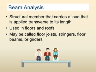
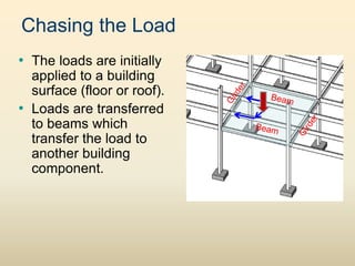
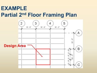
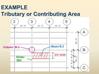
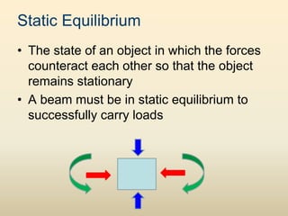
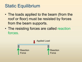
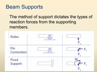
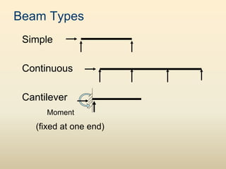
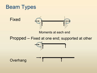
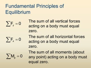
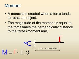
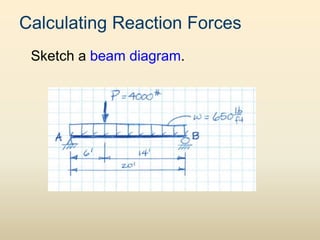
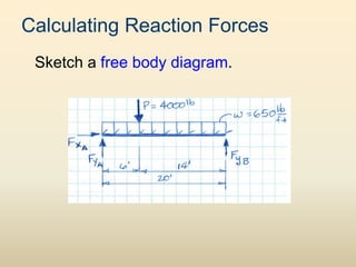
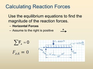
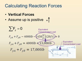
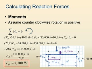
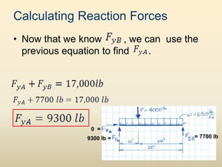
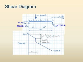
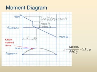
‱ Structural member that carries a load that
is applied transverse to its length
‱ Used in floors and roofs
‱ May be called floor joists, stringers, floor
beams, or girders
Beam Analysis
‱ The loads are initially
applied to a building
surface (floor or roof).
‱ Loads are transferred
to beams which
transfer the load to
another building
component.
Chasing the Load
EXAMPLE
Partial 2nd Floor Framing Plan
Design Area
EXAMPLE
Tributary or Contributing Area
6’8” Width
Column B-3 Beam B.3
Girder
3BC
Static Equilibrium
‱ The state of an object in which the forces
counteract each other so that the object
remains stationary
‱ A beam must be in static equilibrium to
successfully carry loads
Static Equilibrium
‱ The loads applied to the beam (from the
roof or floor) must be resisted by forces
from the beam supports.
‱ The resisting forces are called reaction
forces.
Applied Load
Reaction
Force
Reaction
Force
Reaction Forces
‱ Reaction forces can be linear or rotational.
– A linear reaction is often called a shear
reaction (F or R).
– A rotational reaction is often called a moment
reaction (M).
‱ The reaction forces must balance the
applied forces.
Beam Supports
The method of support dictates the types of
reaction forces from the supporting
members.
Beam Types
Simple
Continuous
Cantilever
Moment
(fixed at one end)
Beam Types
Fixed
Moments at each end
Propped – Fixed at one end; supported at other
Overhang
Simple Beams
Applied Load
BEAM DIAGRAM
FREE BODY DIAGRAM
Applied Load
Note: When there is no applied
horizontal load, you may
ignore the horizontal reaction
at the pinned connection.
Fundamental Principles of
Equilibrium
The sum of all vertical forces
acting on a body must equal
zero.
The sum of all horizontal forces
acting on a body must equal
zero.
The sum of all moments (about
any point) acting on a body must
equal zero.

 y
F 0

 x
F 0

 p
M 0
Moment
‱ A moment is created when a force tends
to rotate an object.
‱ The magnitude of the moment is equal to
the force times the perpendicular distance
to the force (moment arm).
F
M
M d
F
  
d moment arm
 
Calculating Reaction Forces
Sketch a beam diagram.
Calculating Reaction Forces
Sketch a free body diagram.
Calculating Reaction Forces
Use the equilibrium equations to find the
magnitude of the reaction forces.
– Horizontal Forces
– Assume to the right is positive +

 x
F 0
Calculating Reaction Forces
‱ Vertical Forces
‱ Assume up is positive +
Equivalent
Concentrated Load
Equivalent
Concentrated Load

 y
F 0
Calculating Reaction Forces
‱ Moments
‱ Assume counter clockwise rotation is positive
+
A B
0 =
= 7700 lb
20 4000 6 13 000 10 0 0
       
yB yA
( F ft ) ( lb ft ) ( , lb ft ) ( F )
20 24 000 130 000 0 0
     
yB
( ft )F , ft lb , ft lb
20 154 000
 
yB
( ft )F , ft lb
154 000
20


yB
, ft lb
F
ft
7 700

yB
F , lb
Calculating Reaction Forces
‱ Now that we know , we can use the
previous equation to find .
= 7700 lb
9300 lb =
0 =
Shear Diagram
= 7700 lb
9300 lb =
0 =
Moment Diagram
1400
215
650
 
lb
ft
lb
x . ft
Kink in
moment
curve
Moment Diagram
9300 lb =
0 =
4000 lb
2.15’
M
P
    
. ft
lb
ft
( lb)( . ft ) ( )(
M . ft ) ( ) ( lb)( . ft )
815
2
4000 215 650 815 9300 815 0
45608
  
max
M
M ft lb
Moment Diagram
Moment Diagram
A
B
C
= 2.15 ft
Beam Analysis
‱ Example : simple beam with a uniform
load, w1= 1090 lb/ft
‱ Span = 18 feet
Test your understanding: Draw the shear and moment
diagrams for this beam and loading condition.
Moment
Shear
Max. Moment = 44,145l ft-lb Max. Shear = 9,810 lb
Shear and Moment Diagrams

beamanalysis.ppt

  • 1.
    ‱ Structural memberthat carries a load that is applied transverse to its length ‱ Used in floors and roofs ‱ May be called floor joists, stringers, floor beams, or girders Beam Analysis
  • 2.
    ‱ The loadsare initially applied to a building surface (floor or roof). ‱ Loads are transferred to beams which transfer the load to another building component. Chasing the Load
  • 3.
    EXAMPLE Partial 2nd FloorFraming Plan Design Area
  • 4.
    EXAMPLE Tributary or ContributingArea 6’8” Width Column B-3 Beam B.3 Girder 3BC
  • 5.
    Static Equilibrium ‱ Thestate of an object in which the forces counteract each other so that the object remains stationary ‱ A beam must be in static equilibrium to successfully carry loads
  • 6.
    Static Equilibrium ‱ Theloads applied to the beam (from the roof or floor) must be resisted by forces from the beam supports. ‱ The resisting forces are called reaction forces. Applied Load Reaction Force Reaction Force
  • 7.
    Reaction Forces ‱ Reactionforces can be linear or rotational. – A linear reaction is often called a shear reaction (F or R). – A rotational reaction is often called a moment reaction (M). ‱ The reaction forces must balance the applied forces.
  • 8.
    Beam Supports The methodof support dictates the types of reaction forces from the supporting members.
  • 9.
  • 10.
    Beam Types Fixed Moments ateach end Propped – Fixed at one end; supported at other Overhang
  • 11.
    Simple Beams Applied Load BEAMDIAGRAM FREE BODY DIAGRAM Applied Load Note: When there is no applied horizontal load, you may ignore the horizontal reaction at the pinned connection.
  • 12.
    Fundamental Principles of Equilibrium Thesum of all vertical forces acting on a body must equal zero. The sum of all horizontal forces acting on a body must equal zero. The sum of all moments (about any point) acting on a body must equal zero.   y F 0   x F 0   p M 0
  • 13.
    Moment ‱ A momentis created when a force tends to rotate an object. ‱ The magnitude of the moment is equal to the force times the perpendicular distance to the force (moment arm). F M M d F    d moment arm  
  • 14.
  • 15.
  • 16.
    Calculating Reaction Forces Usethe equilibrium equations to find the magnitude of the reaction forces. – Horizontal Forces – Assume to the right is positive +   x F 0
  • 17.
    Calculating Reaction Forces ‱Vertical Forces ‱ Assume up is positive + Equivalent Concentrated Load Equivalent Concentrated Load   y F 0
  • 18.
    Calculating Reaction Forces ‱Moments ‱ Assume counter clockwise rotation is positive + A B 0 = = 7700 lb 20 4000 6 13 000 10 0 0         yB yA ( F ft ) ( lb ft ) ( , lb ft ) ( F ) 20 24 000 130 000 0 0       yB ( ft )F , ft lb , ft lb 20 154 000   yB ( ft )F , ft lb 154 000 20   yB , ft lb F ft 7 700  yB F , lb
  • 19.
    Calculating Reaction Forces ‱Now that we know , we can use the previous equation to find . = 7700 lb 9300 lb = 0 =
  • 20.
    Shear Diagram = 7700lb 9300 lb = 0 =
  • 21.
  • 22.
    Moment Diagram 9300 lb= 0 = 4000 lb 2.15’ M P      . ft lb ft ( lb)( . ft ) ( )( M . ft ) ( ) ( lb)( . ft ) 815 2 4000 215 650 815 9300 815 0 45608    max M M ft lb
  • 23.
  • 24.
  • 25.
    Beam Analysis ‱ Example: simple beam with a uniform load, w1= 1090 lb/ft ‱ Span = 18 feet Test your understanding: Draw the shear and moment diagrams for this beam and loading condition.
  • 26.
    Moment Shear Max. Moment =44,145l ft-lb Max. Shear = 9,810 lb Shear and Moment Diagrams