Downloaded 413 times

![Experimental Stress Analysis
Department of Mechanical Engineering Page 4
∈ =
1
2
∈ +∈ −
1
2
∈ −∈ +
⁄
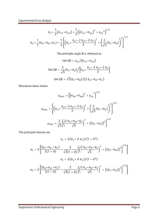
∈ = (∈ +∈ ) − (∈ −∈ ) + 2 ∈ − ( ∈ + ∈ )
⁄
………………….. (5)
Maximum shear strains
= ∈ −∈ +
⁄
= {(∈ −∈ ) + (2 ∈ −∈ −∈ ) } ⁄
……………… (6)
Principal strain directions are
tan2∅ = ∈ −∈⁄
tan 2∅ = [ 2 ∈ − ∈ − ∈ ] (∈ −∈ )⁄ ……. (7)
Substituting eq 5 value in the general eq of the principal stress and and we get
= (∈ + ∈ ) (1 − )⁄
=
2
∈ +∈
(1 − )
+
1
(1 + )
{(∈ −∈ ) + ( 2 ∈ − ∈ − ∈ ) } ⁄
= (∈ + ∈ ) (1 − )⁄
=
2
∈ +∈
(1 − )
−
1
(1 + )
{(∈ −∈ ) + ( 2 ∈ − ∈ − ∈ ) } ⁄
Maximum shear stress is given by
=
2(1 + )
=
2(1 + )
{(∈ −∈ ) + (2 ∈ −∈ −∈ ) } ⁄
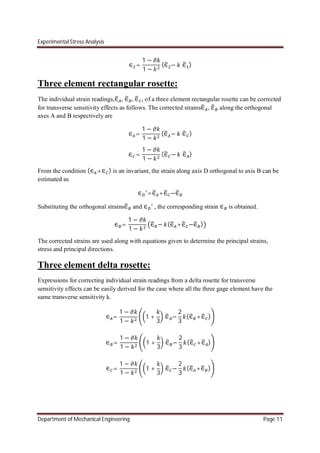
Three element delta rosettes:
In a three element delta rosette three gauges are placed at angular disposition of 0o
,120o
, 240o
.
for a delta rosette,](https://image.slidesharecdn.com/chapter2-170106173021/85/experimental-stress-analysis-Chapter-2-4-320.jpg)
![Experimental Stress Analysis
Department of Mechanical Engineering Page 8
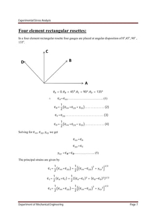
∈ =
1
2
(∈ +∈ ) −
1
2
{(∈ −∈ ) + (∈ −∈ ) } ⁄
tan2∅ = ∈ −∈⁄
∅ =
1
2
tan
∈ −∈
∈ −∈
The principal stress are given by
= (∈ + ∈ ) (1 − )⁄
=
2
(∈ +∈ )
(1 − )
+
[(∈ −∈ ) + (∈ −∈ ) ] ⁄
(1 + )
= (∈ + ∈ ) (1 − )⁄
=
2
(∈ +∈ )
(1 − )
−
[(∈ −∈ ) + (∈ −∈ ) ] ⁄
(1 + )
Maximum shear strains
= ∈ −∈ +
⁄
= {(∈ −∈ ) + (∈ −∈ ) } ⁄
Maximum shear stress is given by
=
2(1 + )
=
2(1 + )
{(∈ −∈ ) + (∈ −∈ ) } ⁄
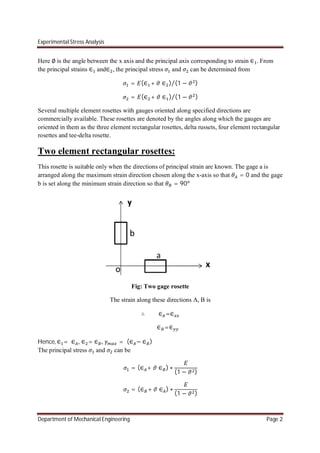
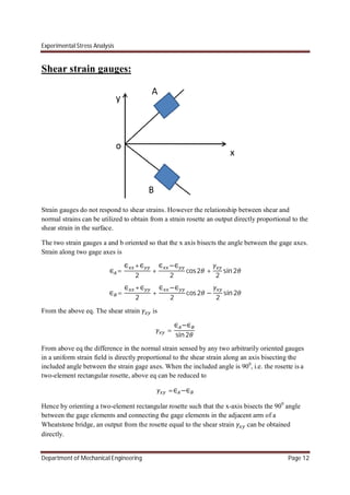
Four element delta rosettes:
In a four element rectangular rosette four gauges are placed at angular disposition of 0o
,60o
, 120o
, 90o
.
= 0, = 60 , = 120 , = 90
∴ ∈ =∈ …………………………….. (1)
∈ =
1
4
∈ + 3 ∈ + √3 … … … … … … … (2)](https://image.slidesharecdn.com/chapter2-170106173021/85/experimental-stress-analysis-Chapter-2-8-320.jpg)
![Experimental Stress Analysis
Department of Mechanical Engineering Page 14
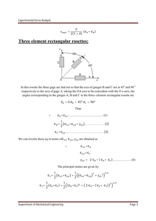
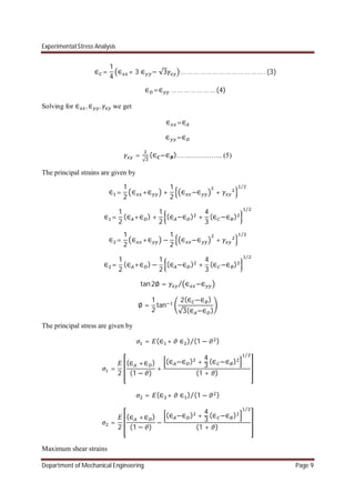
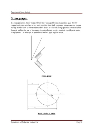
Fig 1 shows the sketch of a stress gage with its axis along the x-axis. The gage is oriented such
that the x-axis bisects the angle 2 between the grid elements A and B of this gage.
The strains along the grid elements A and B are given by
∈ = ( + ) + ( − ) 2( − )…………. (a)
∈ = ( + ) + ( − ) 2( + )………… (b)
The average of these will be
∈ +∈ = ( + ) + ( − )[ 2( + ) + 2( − )]…………. (c)
On expanding the cosine terms in above eq
∈ +∈ = ( + ) + ( − ) 2 2 …………. (d)
From Mohr’s strain circle
∈ +∈ =∈ +∈ ………..... (e)
∈ −∈ = (∈ −∈ )cos2 ………. (f)
Substituting the values in eq e and f in eq d and simplifying
1
2
∈ +∈ =
1
2
+ +
1
2
− 2
1
2
∈ +∈ =
1
2
+ +
1
2
− (2 − 1)
1
2
∈ +∈ =
1
2
+ + − −
1
2
−
1
2
∈ +∈ = − +
1
2
∈ +∈ = + (1 − )
1
2
∈ +∈ = +
∈ +∈ = + ……………….(g)
If is so chosen that it is equal to tan √ then
=](https://image.slidesharecdn.com/chapter2-170106173021/85/experimental-stress-analysis-Chapter-2-14-320.jpg)

- Strain gauges oriented in different directions and arranged in a rosette configuration are used to determine principal strains and stresses at a point. - Several types of rosette configurations are commonly used, including rectangular, delta, and tee rosettes with varying numbers and orientations of strain gauges. - Simultaneous equations relating strain readings from each gauge to the principal strains are solved to determine the principal strain values and orientations. - Principal stresses are then calculated from the principal strains using stress-strain relationships accounting for Poisson's ratio.


