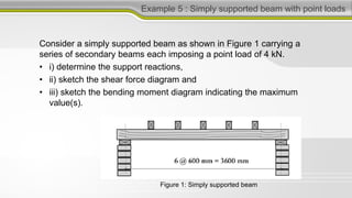
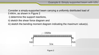
This document discusses structural analysis and beam analysis. It covers topics such as support reactions, shear force and bending moment diagrams, equilibrium of forces in structures, and determinacy. Key points include:
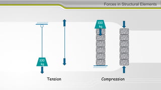
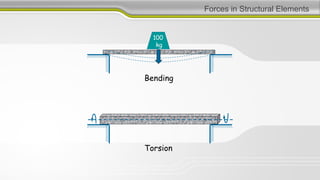
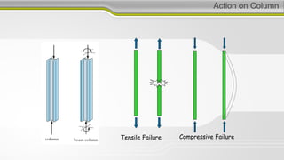
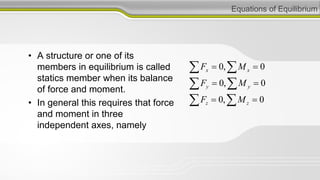
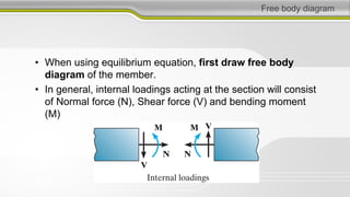
1. To design structures, it is necessary to know bending moments, torsion moments, shear forces, and axial forces in each member.
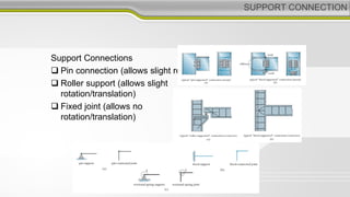
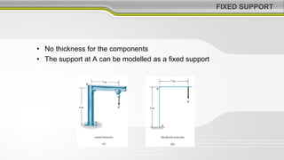
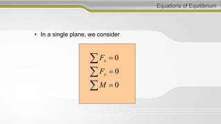
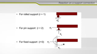
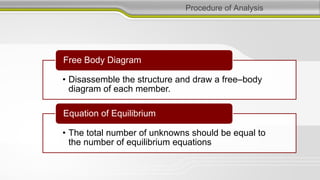
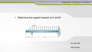
2. Equilibrium requires that the downward forces from gravity have equal and opposite upward reaction forces.
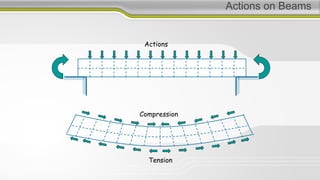
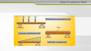
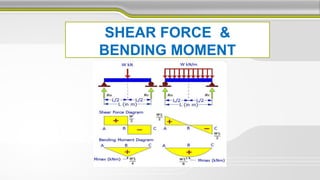
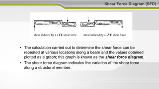
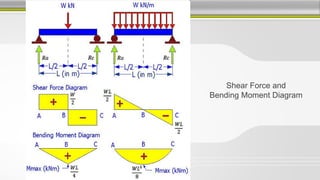
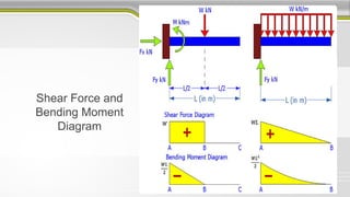
3. Shear force and bending moment diagrams show the variation of these internal forces along a beam under different loading conditions.