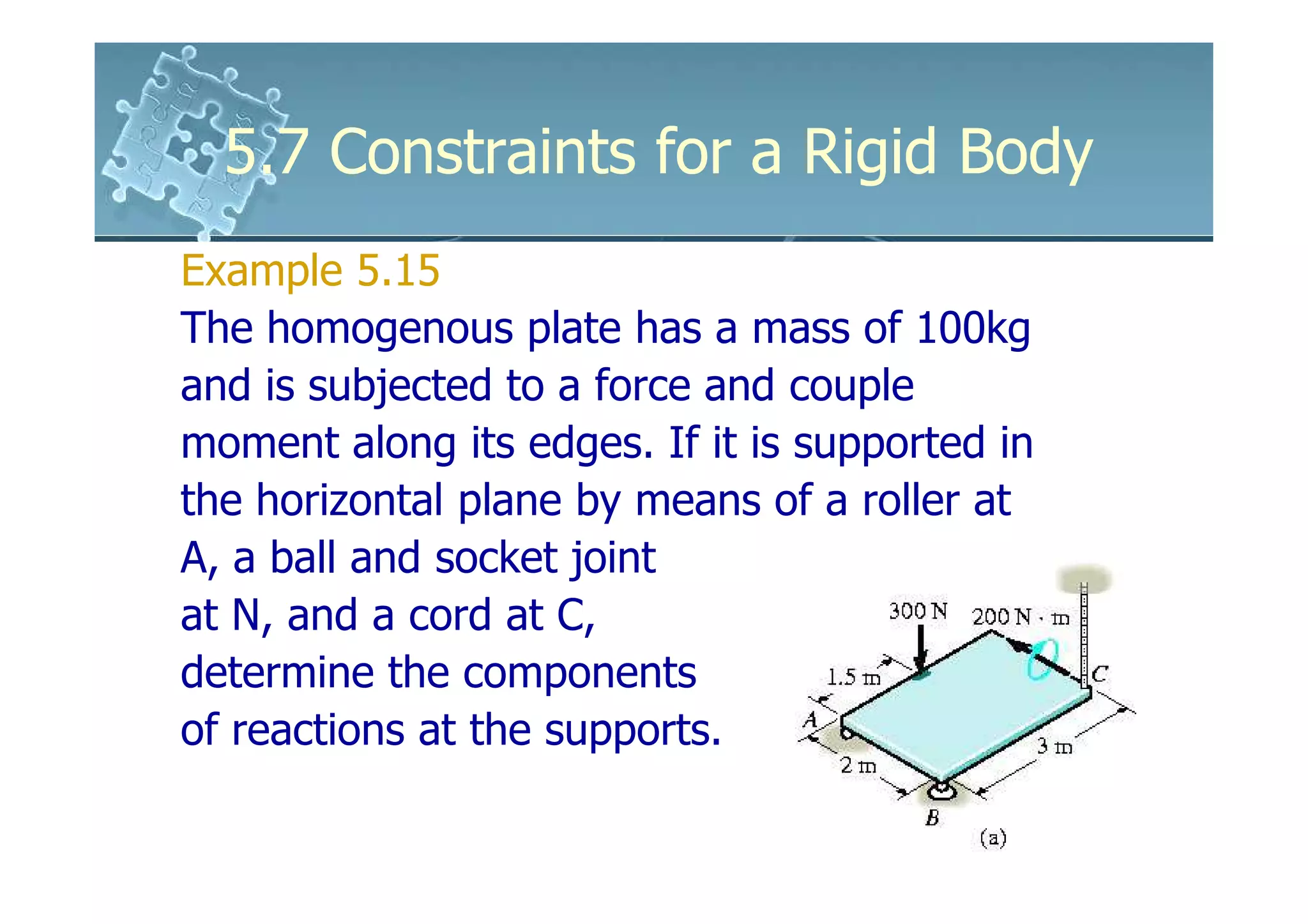
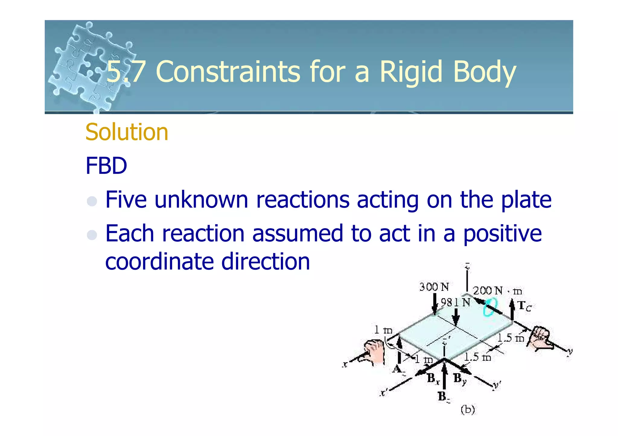
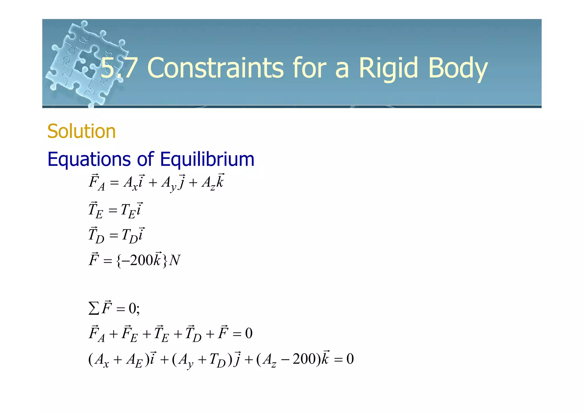
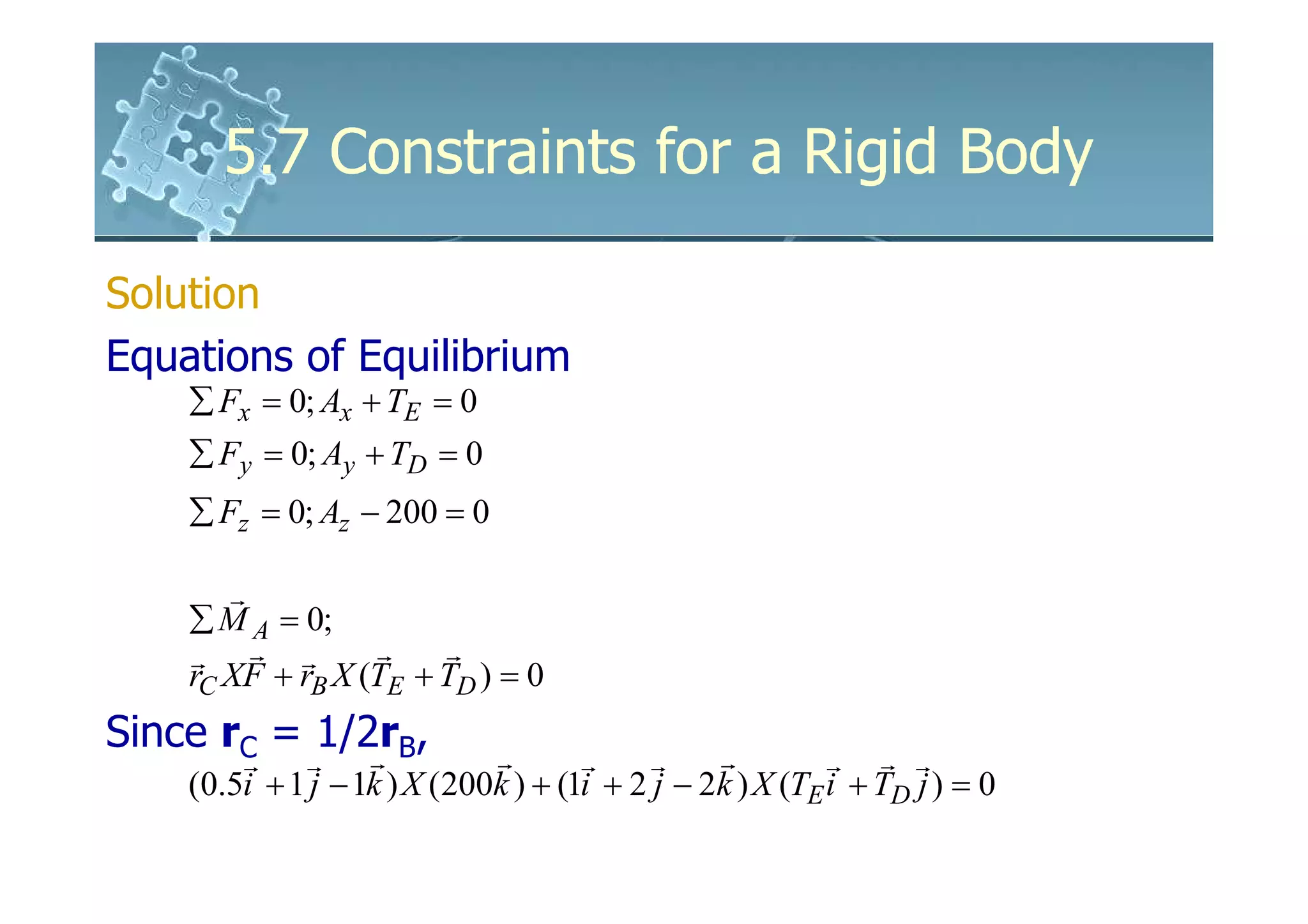
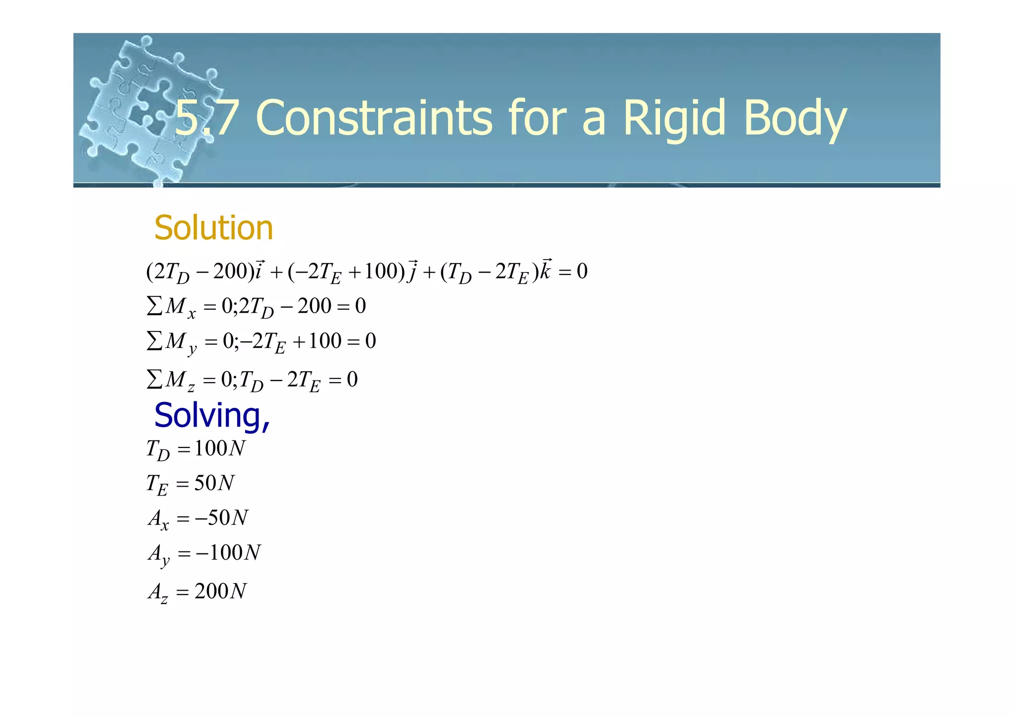
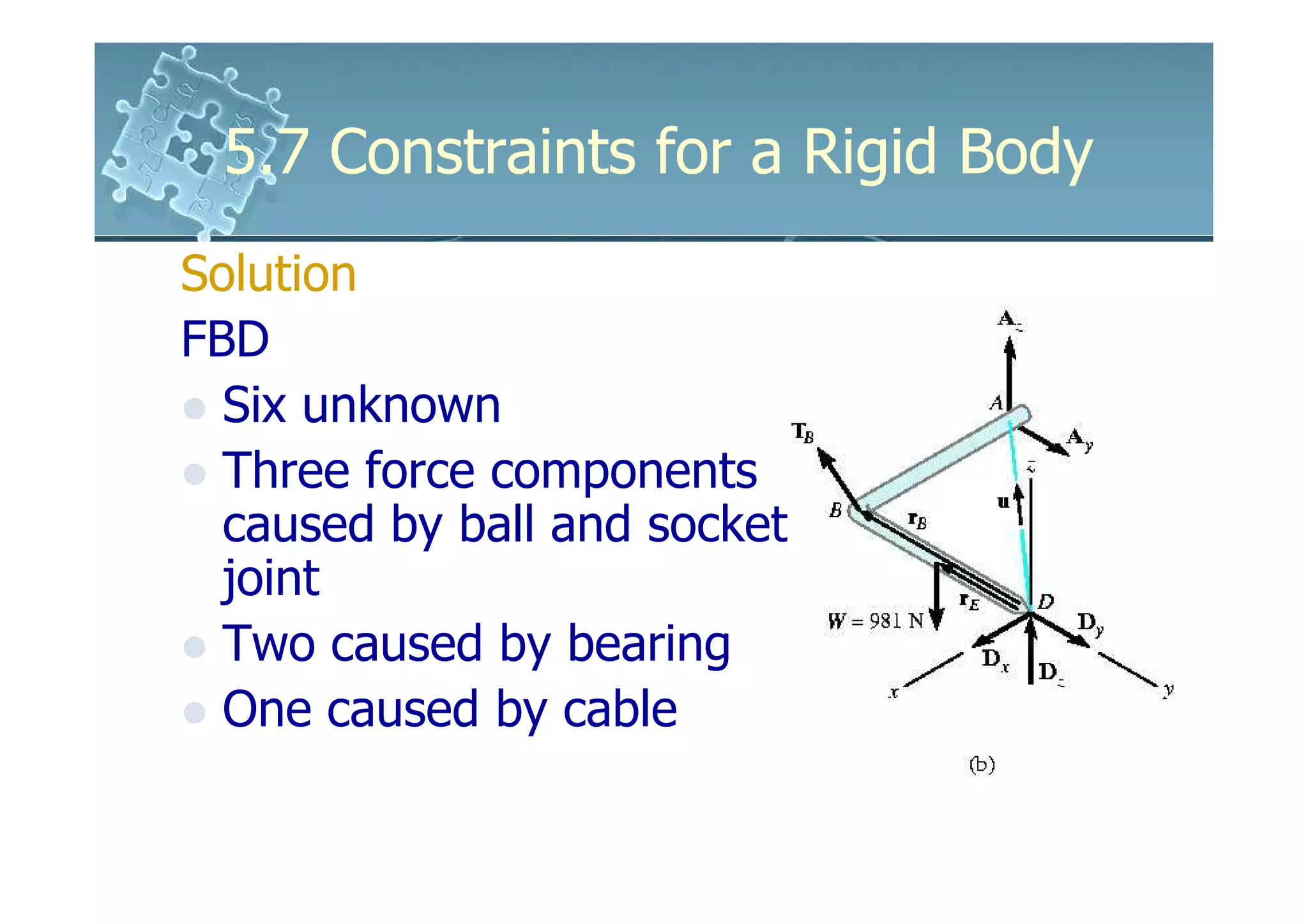
The document discusses constraints for rigid bodies, including:
- Proper constraints require support reactions that do not intersect along a common axis and are not all parallel. This allows the body to be in static equilibrium.
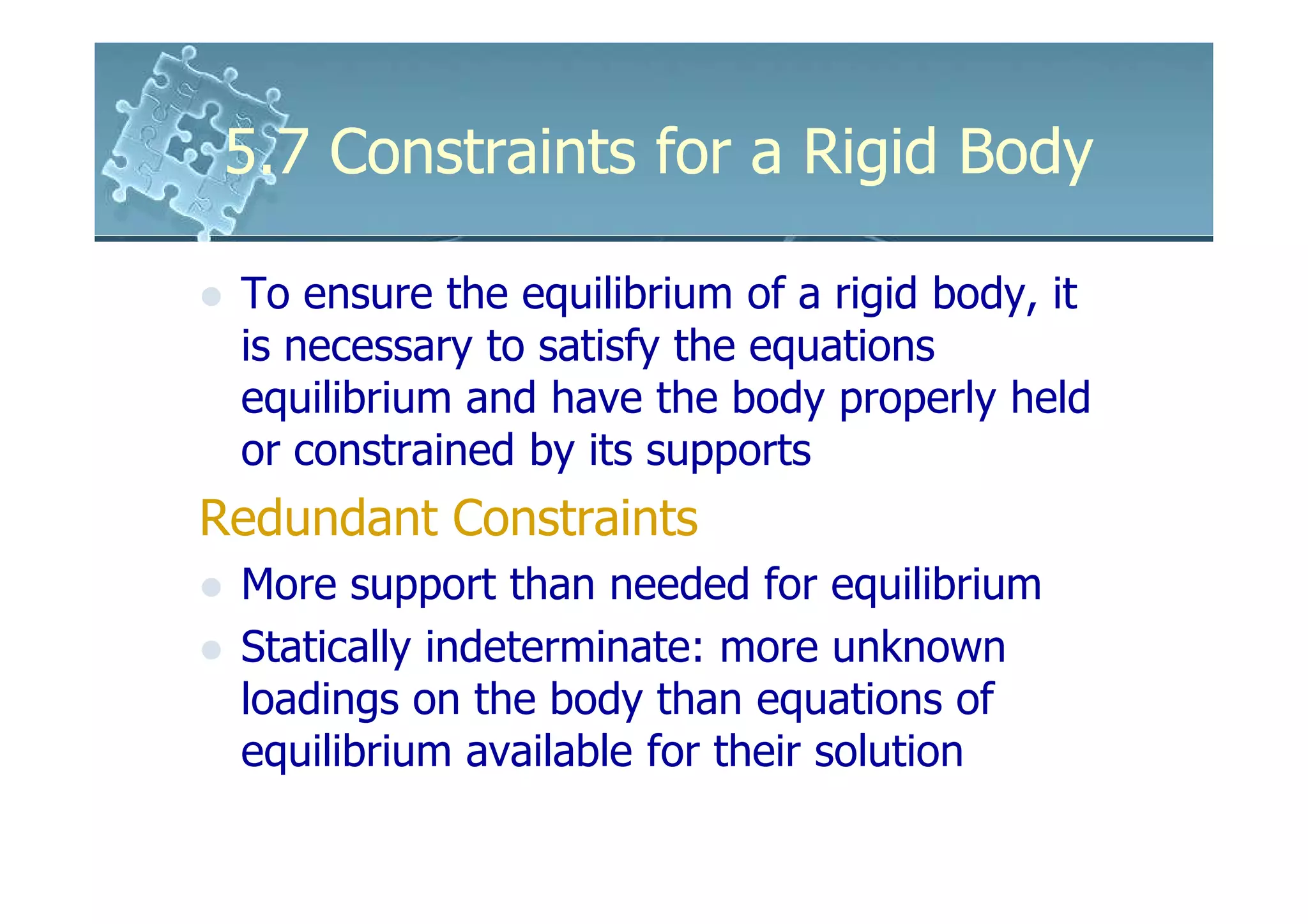
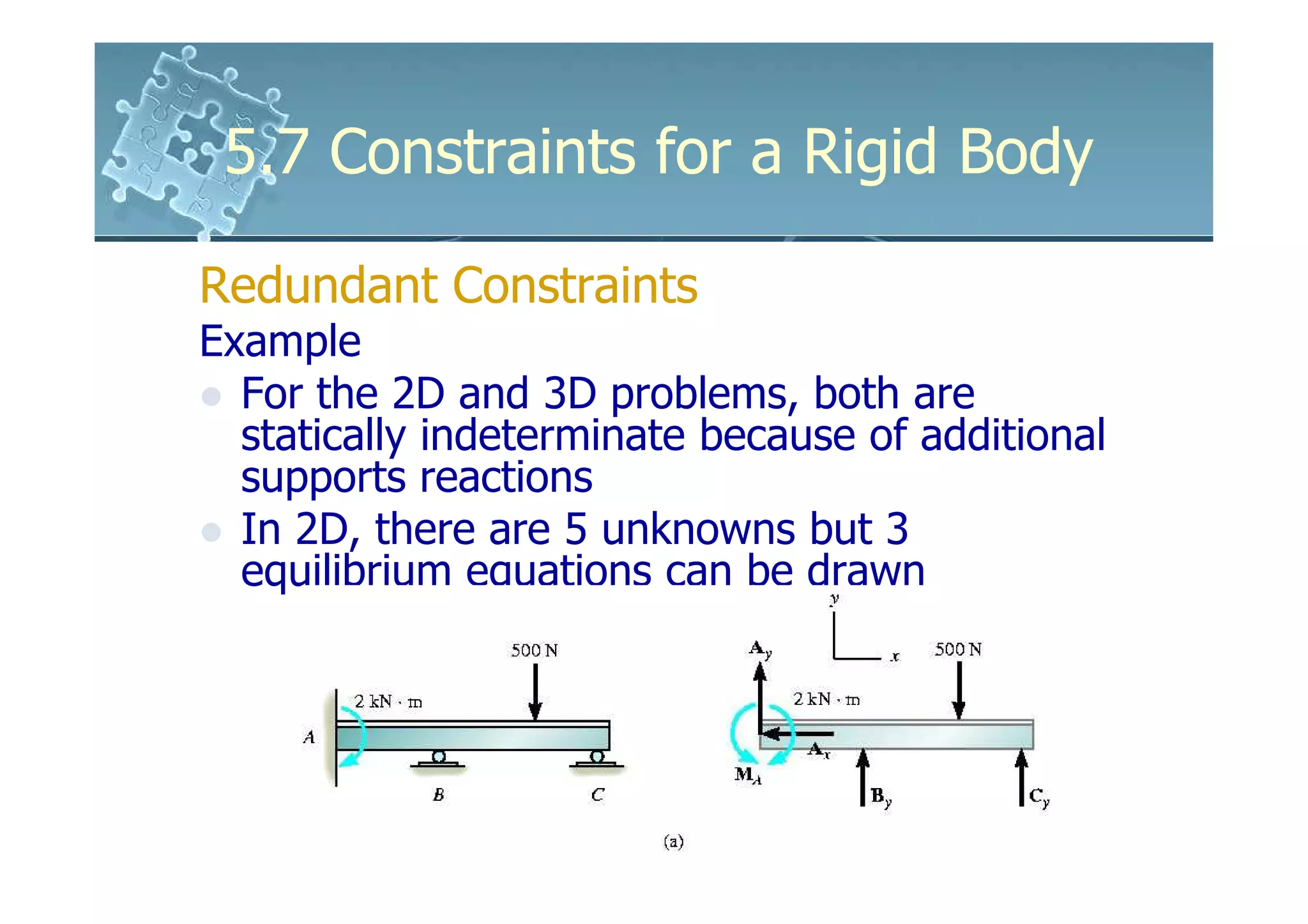
- Redundant constraints have more supports than needed for equilibrium, making problems statically indeterminate.
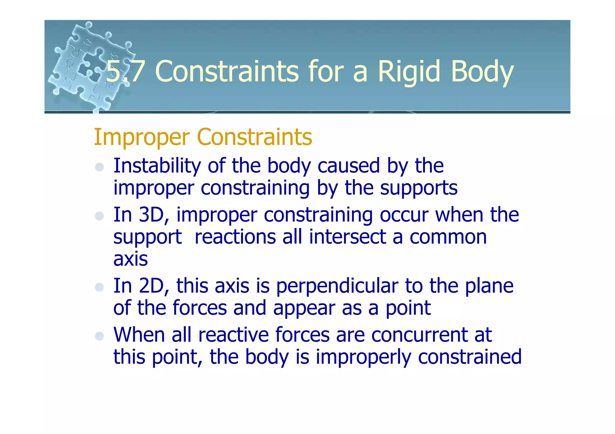
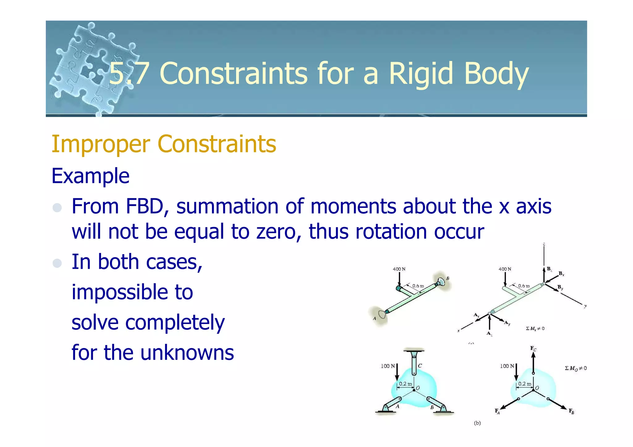
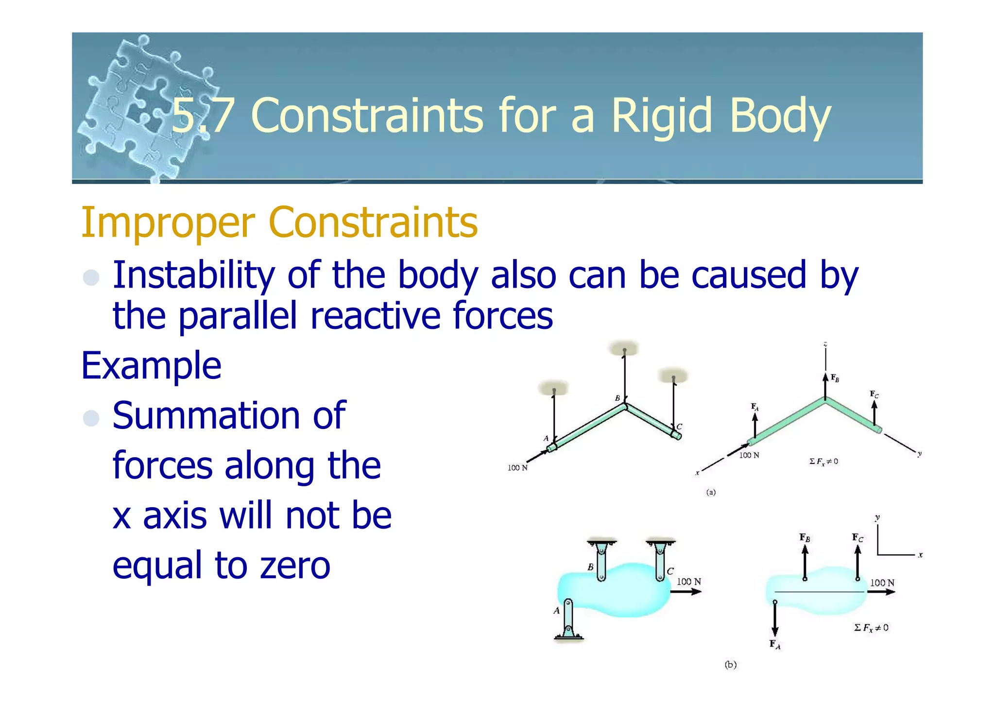
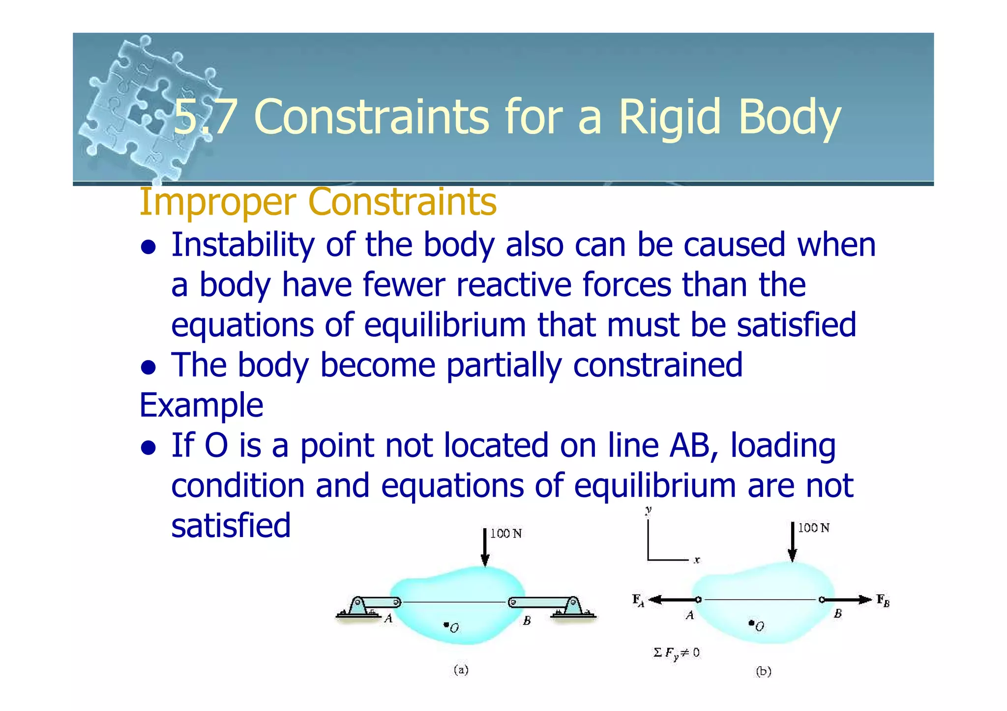
- Improper constraints cause instability by supports intersecting along an axis or having parallel reactive forces, preventing static equilibrium.
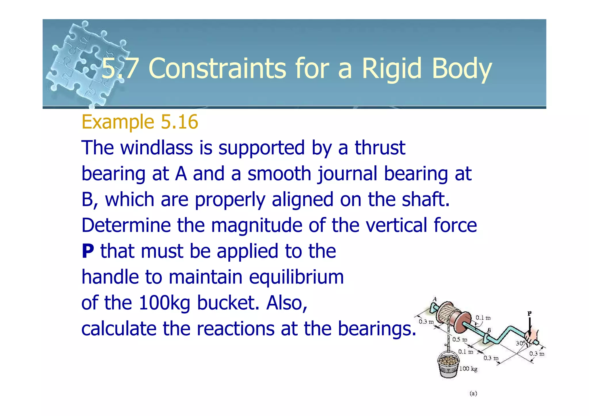
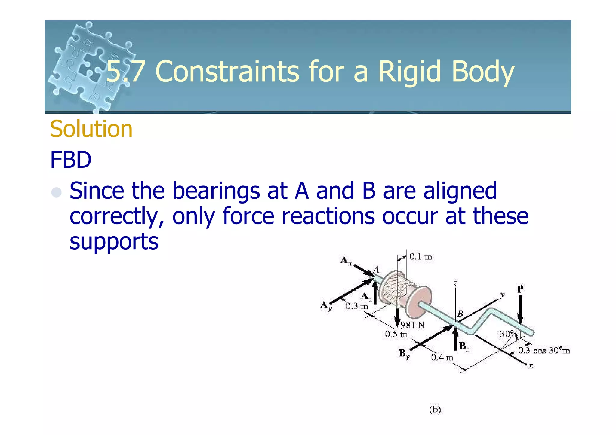
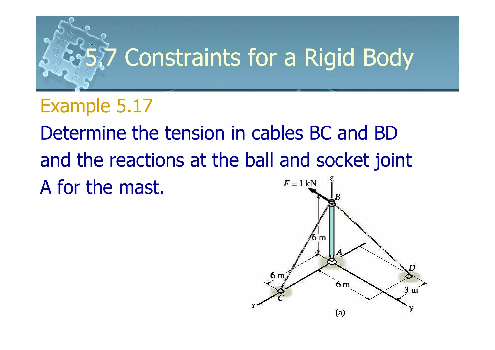
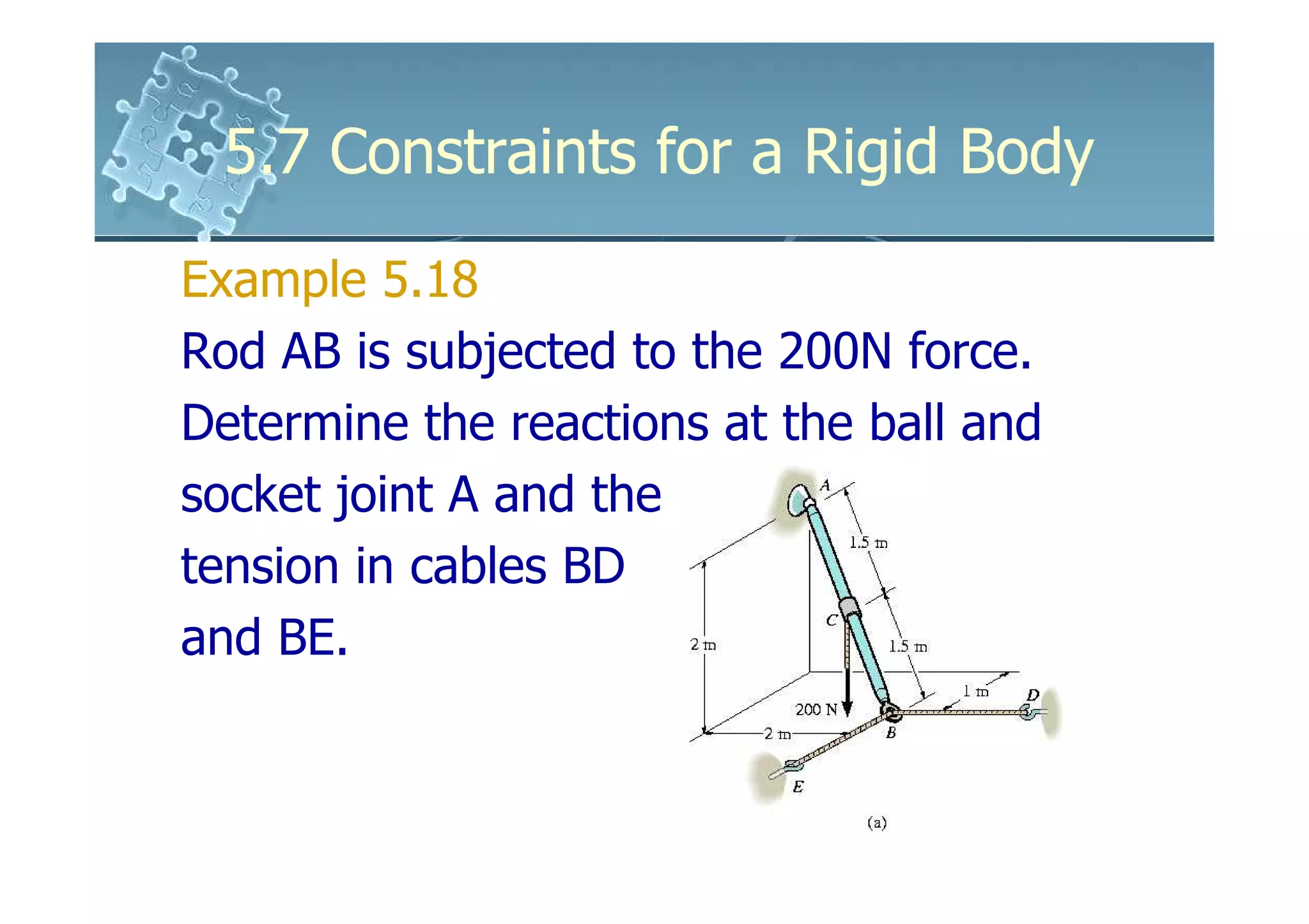
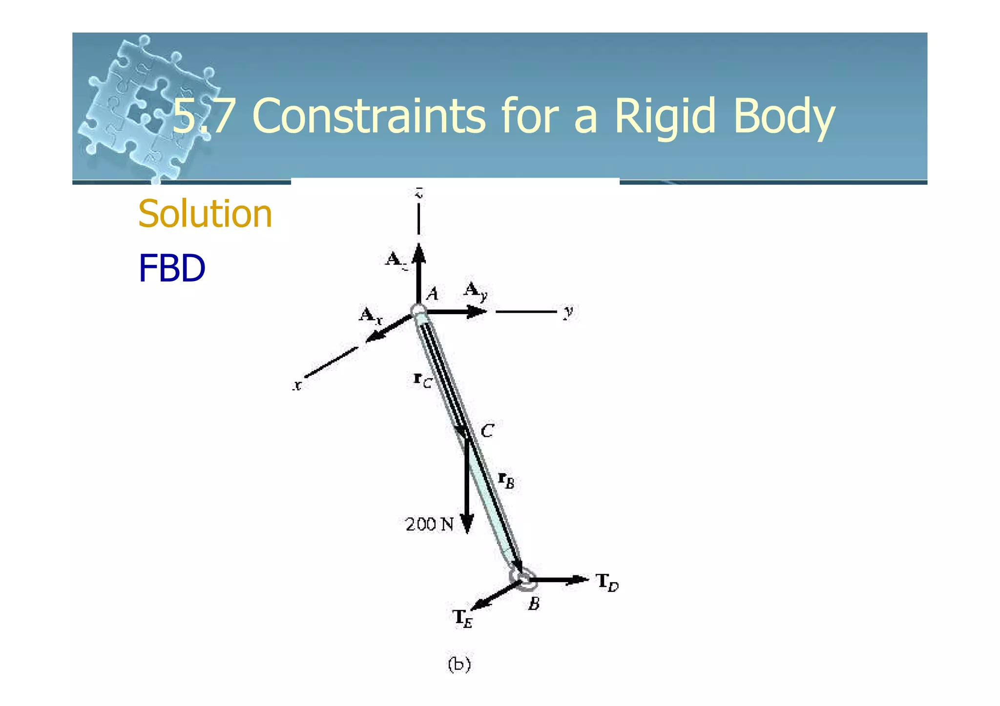
- Analysis requires drawing a free body diagram and applying equations of static equilibrium to solve for unknown support reactions. Examples demonstrate this process.

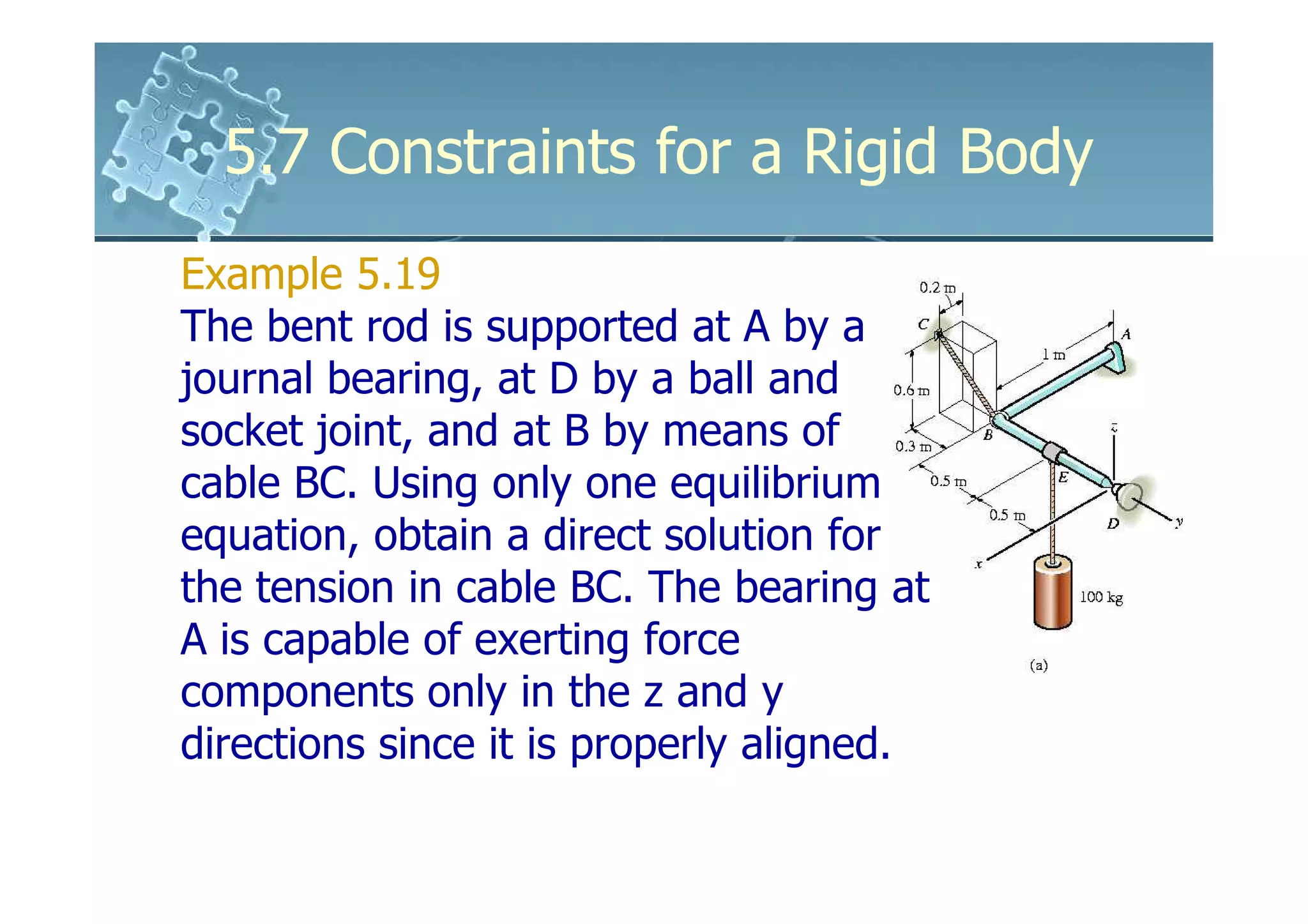
![5.7 Constraints for a Rigid Body
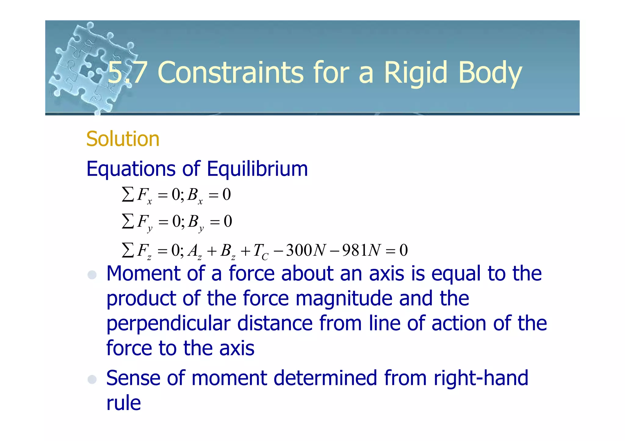
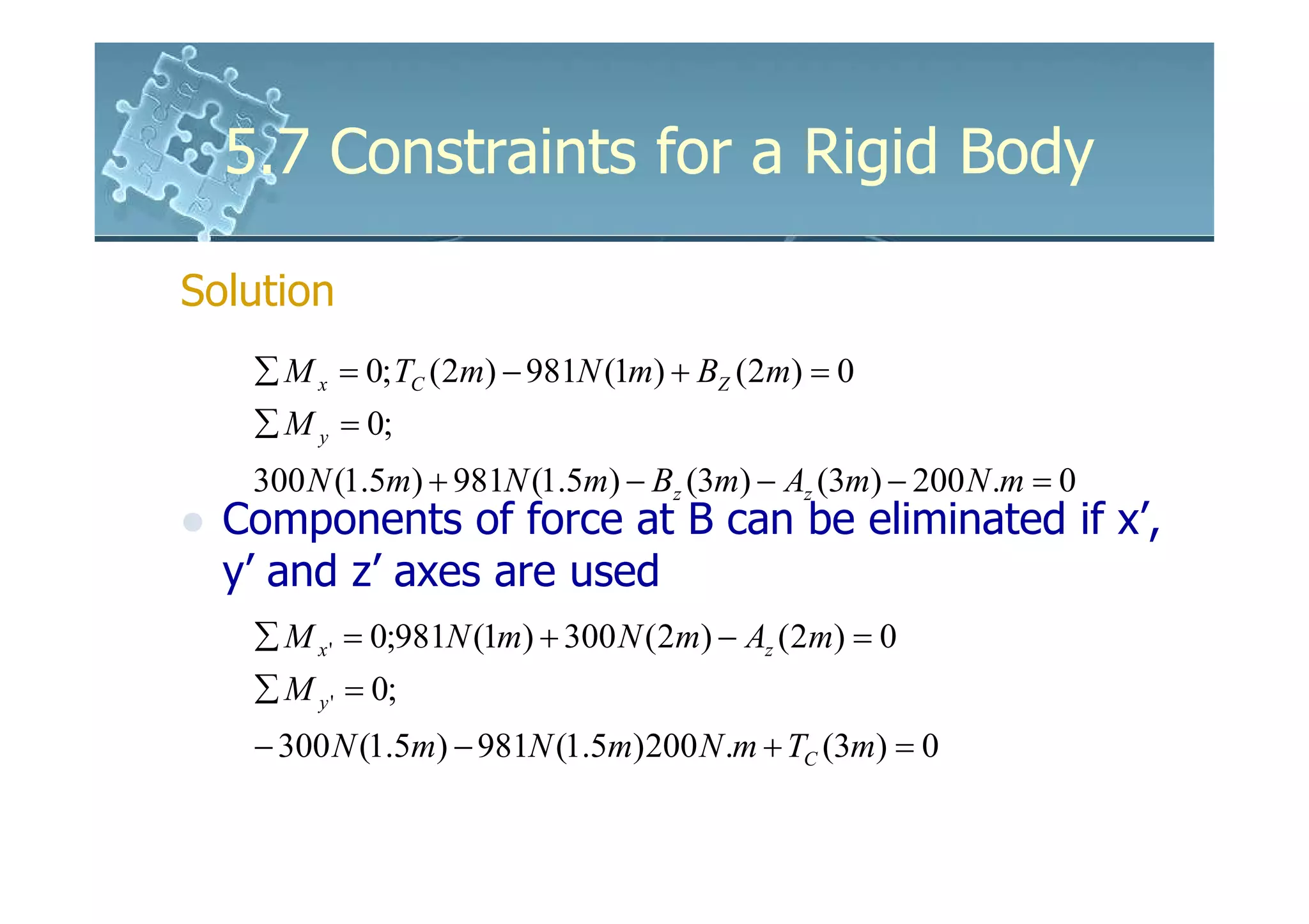
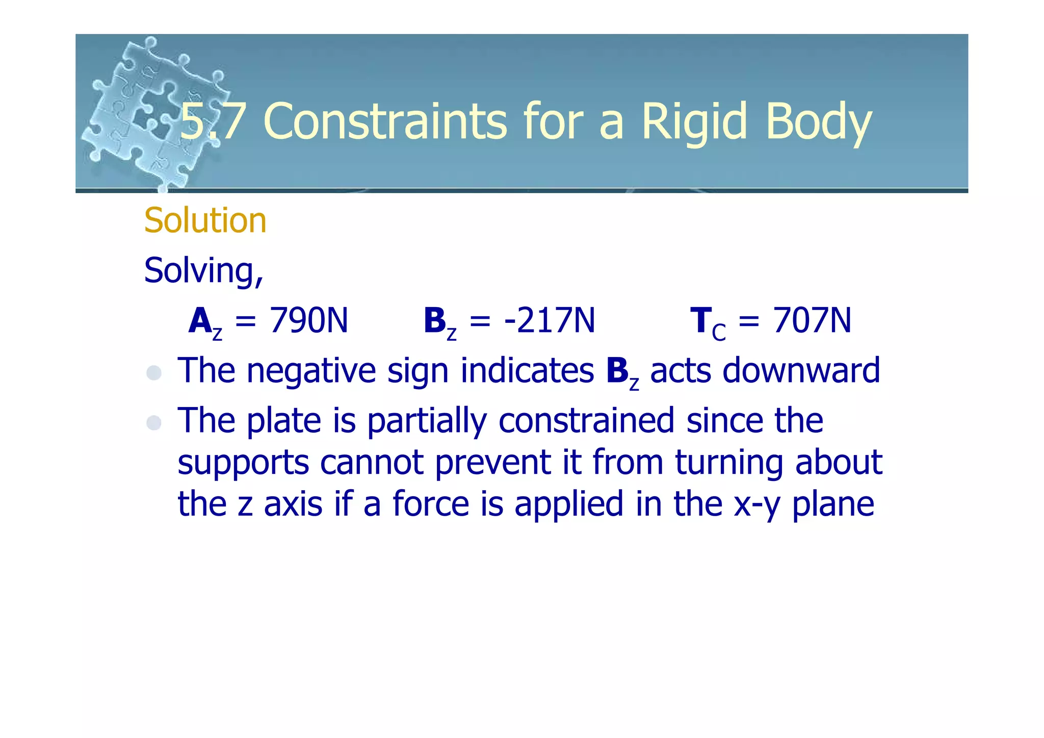
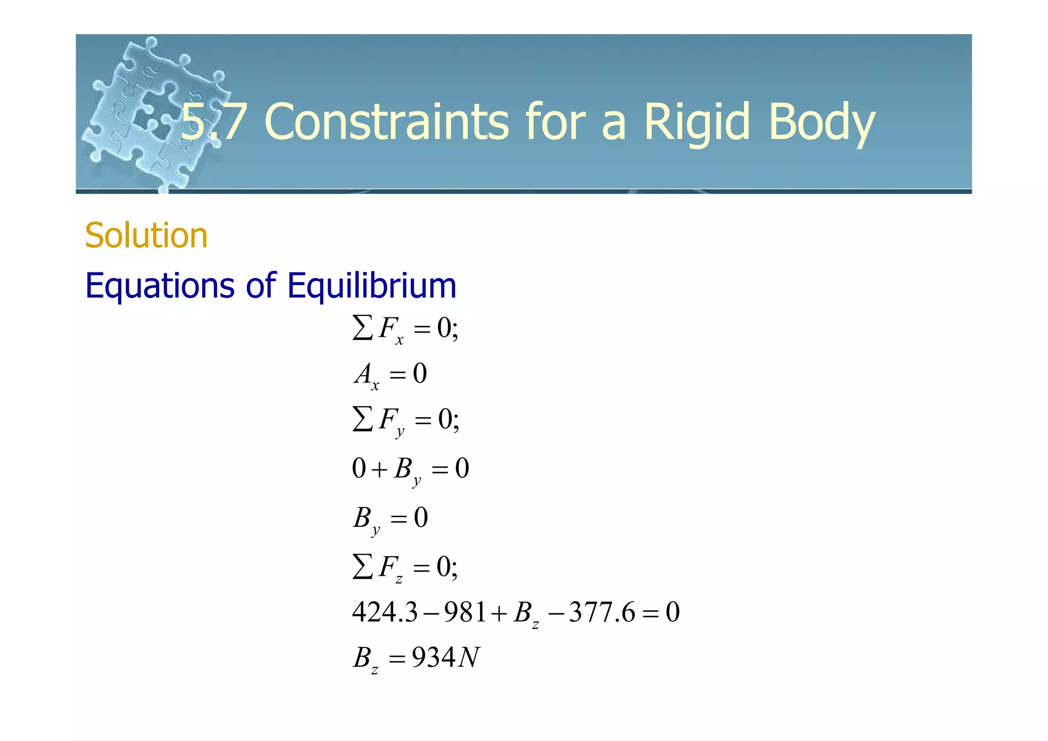
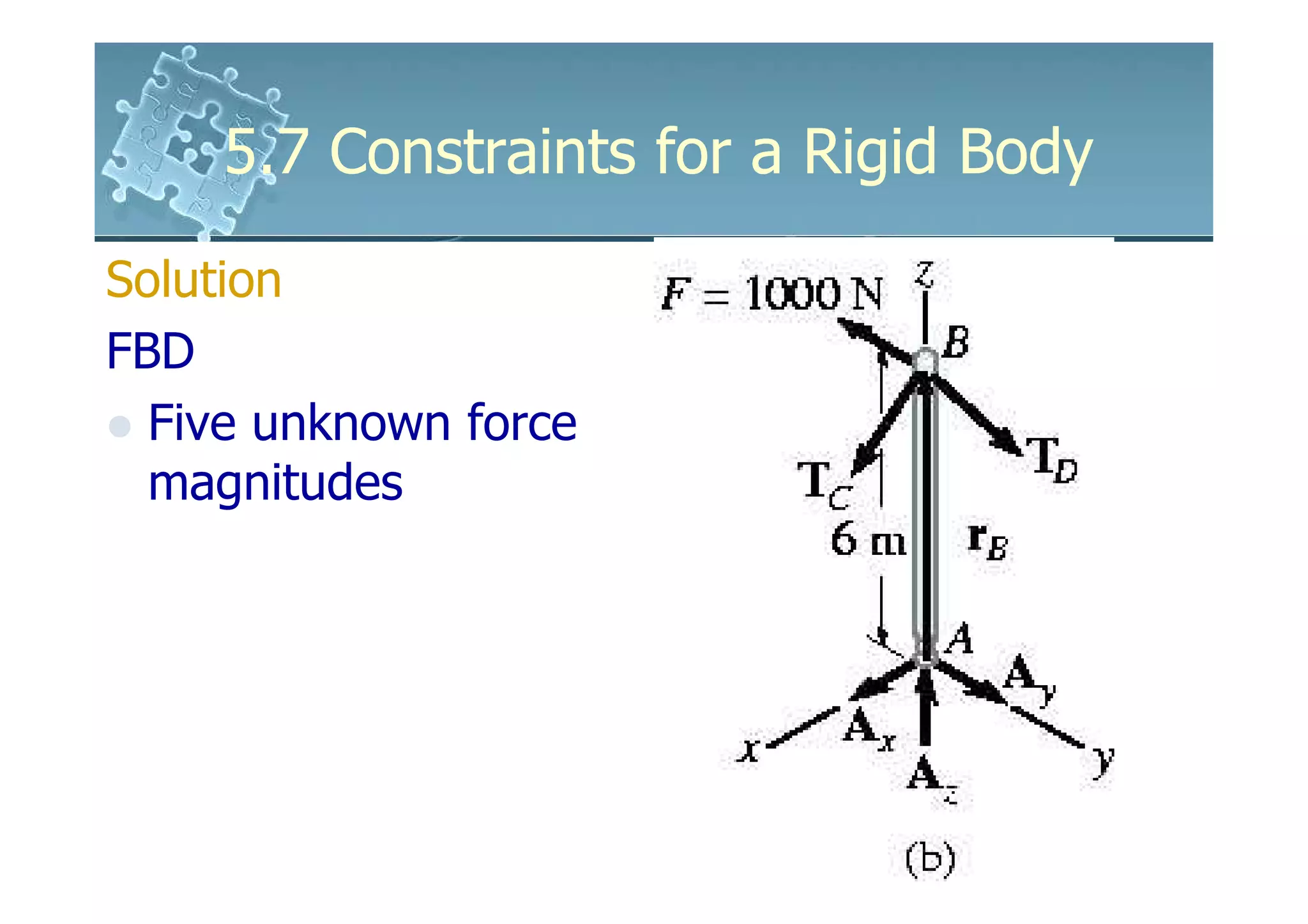
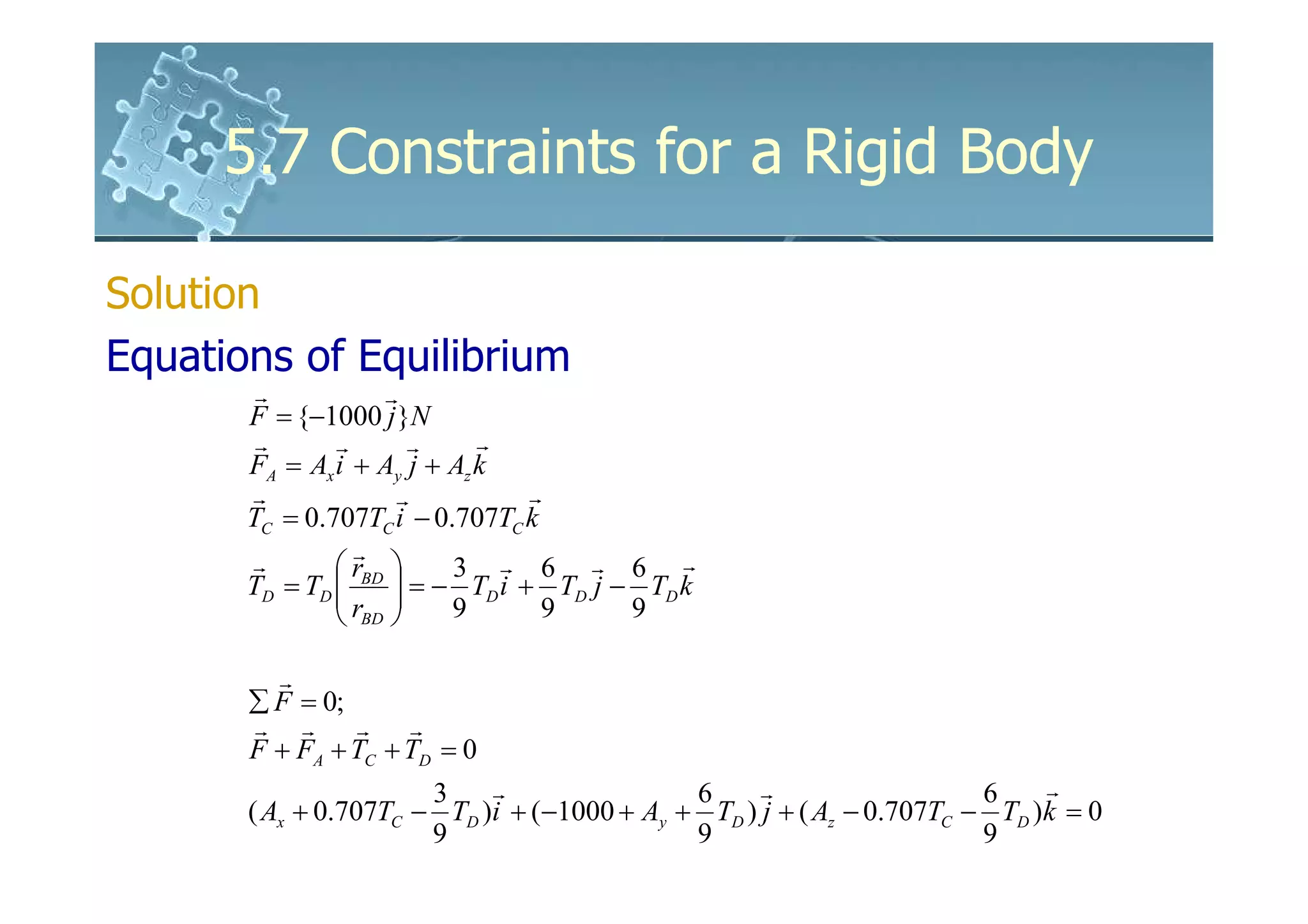
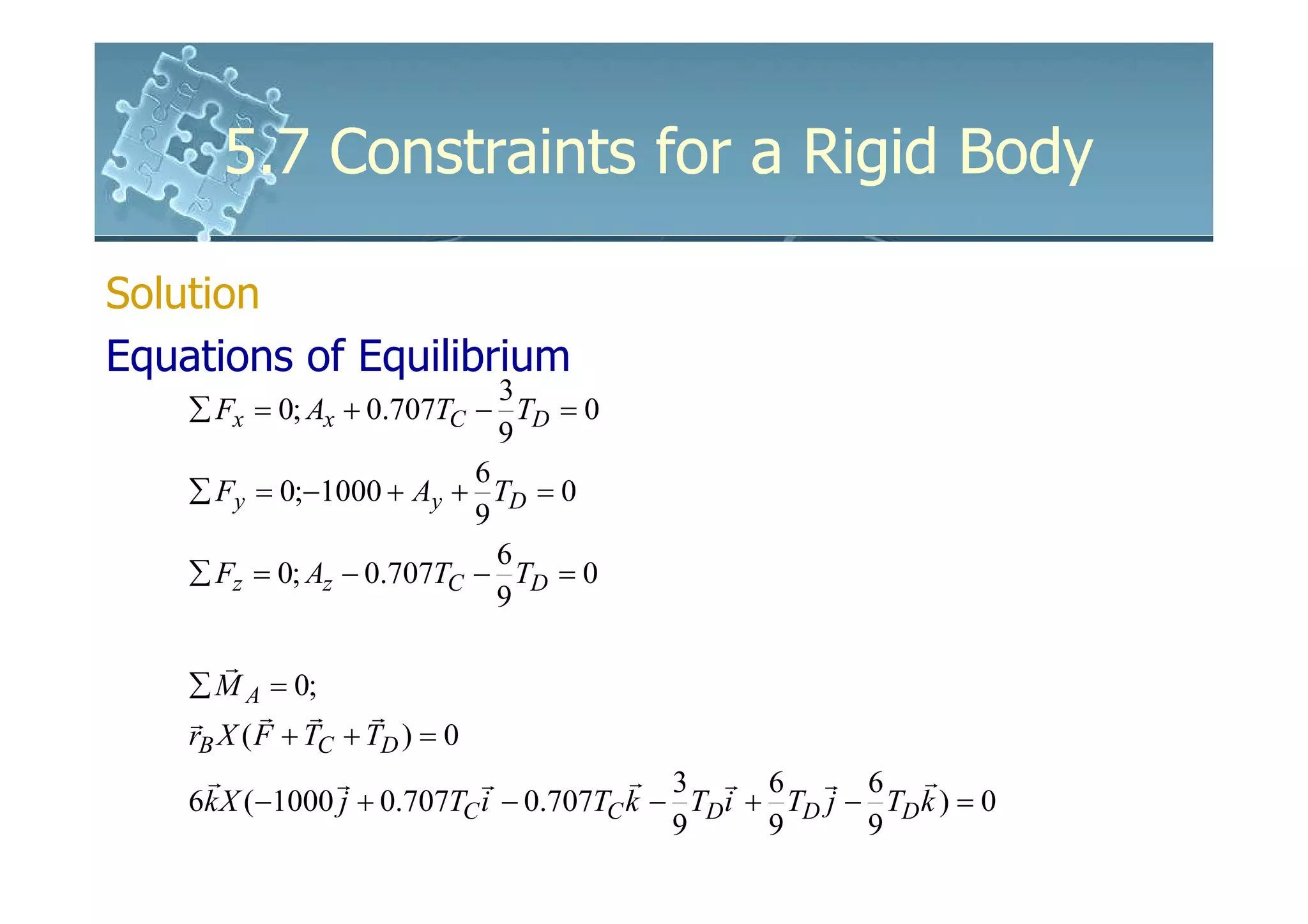
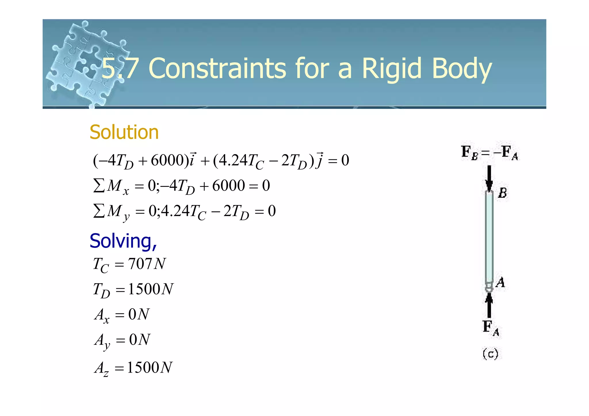
Solution
Equations of Equilibrium
u ⋅ (rB XTB + rE XW ) = 0
0 .2 0.3 0 .6
( −0.707i − 0.707 j ).[(−1 j ) X ( TB i − TB j + TB k )
0 .7 0 .7 0.7
+ (−0.5 j ) X (−981k )] = 0
( −0.707i − 0.707 j ).[(−0.8577TB + 490.5)i + 0.286TB k ] = 0
490.5
TB = = 572 N
0.857](https://image.slidesharecdn.com/61611035-7constraintsforarigidbody-120120021403-phpapp02/75/6161103-5-7-constraints-for-a-rigid-body-35-2048.jpg)


![01 01 chapgere[1]](https://cdn.slidesharecdn.com/ss_thumbnails/01-01chapgere1-130611230425-phpapp02-thumbnail.jpg?width=640&height=640&fit=bounds)