Downloaded 94 times


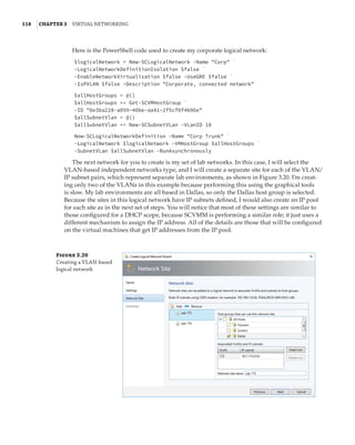
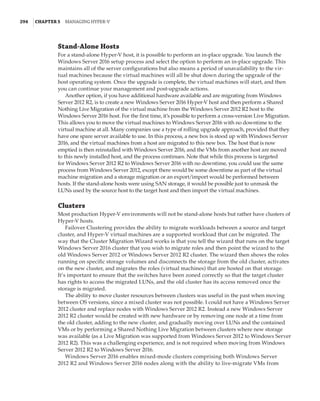
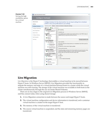
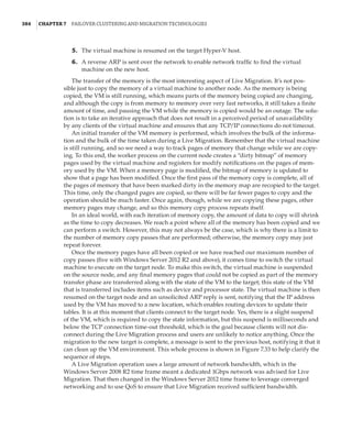
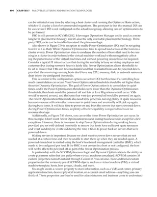
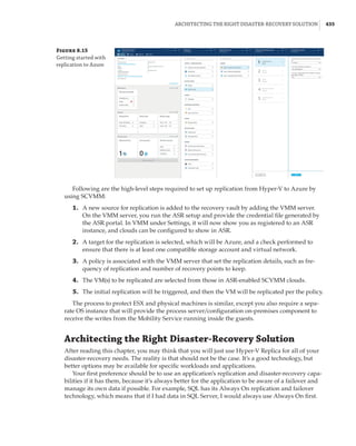
![12 |Chapter 1 Introduction to Virtualization and Microsoft Solutions
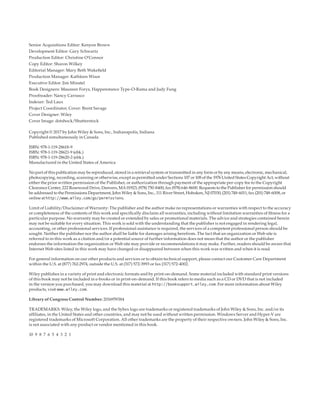
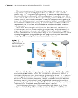
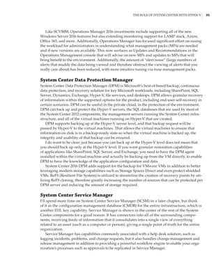
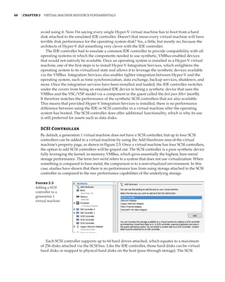
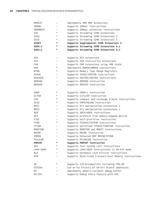
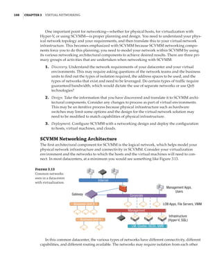
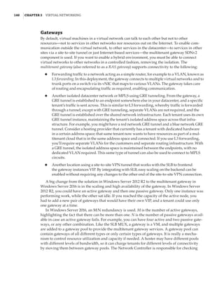
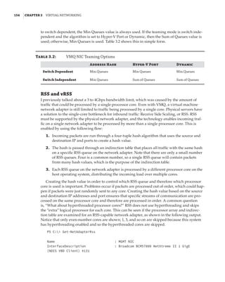
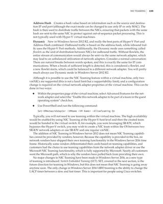
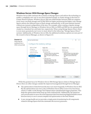
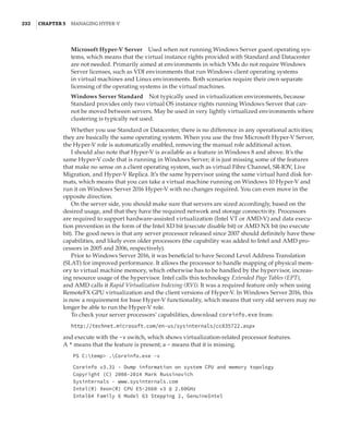
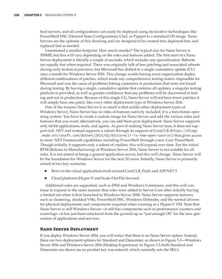
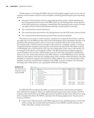
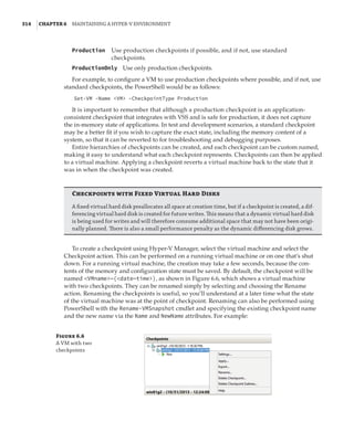
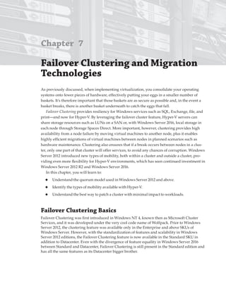
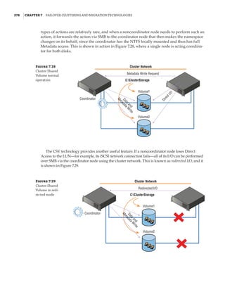
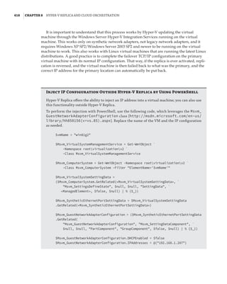
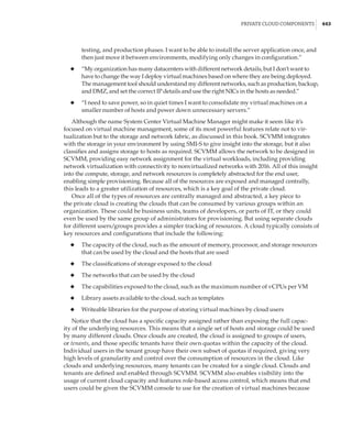
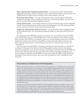
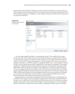
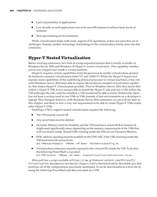
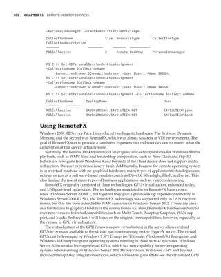
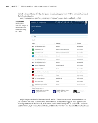
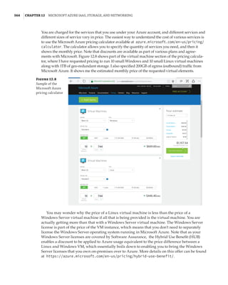
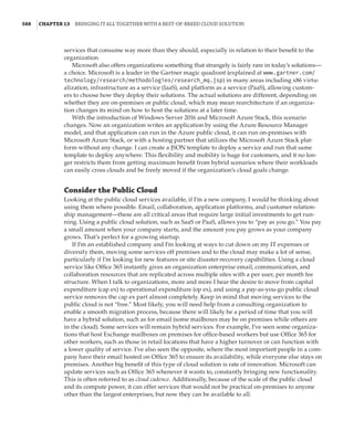
Windows Server 2008 Hyper-V Features
The initial version of Hyper-V provided a solid foundation for virtualization and a fairly lim-
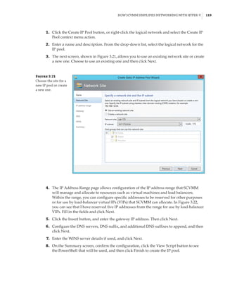
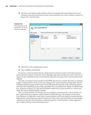
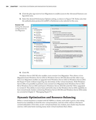
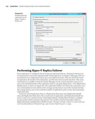
ited set of additional capabilities. As with all versions of Hyper-V, the processors must support
hardware-assisted virtualization (AMD-V or Intel VT) and also Data Execution Prevention
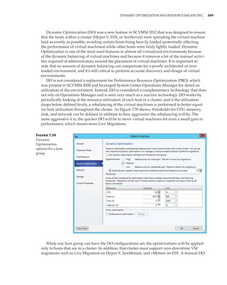
(DEP). Although Hyper-V is available only on 64-bit versions of Windows Server, it is possible to
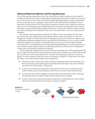
run both 32-bit and 64-bit operating systems. The initial version of Hyper-V included the follow-
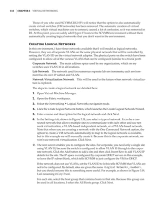
ing key capabilities:
◆
◆ Up to 64GB of memory per VM
◆
◆ Symmetric multiprocessing (SMP) VMs (up to four virtual CPUs [vCPUs] each). However,
the exact number differed depending on the guest operating system. For example,
four vCPUs were supported on Windows Server 2008 SP2 guests, but only two were on
Windows Server 2003 SP2. The full list is available at:
http://technet.microsoft.com/en-us/library/cc794868(v=ws.10).aspx
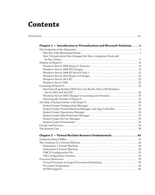
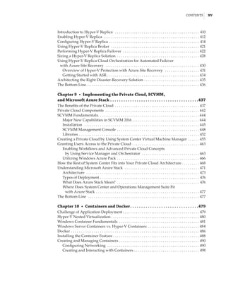
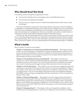
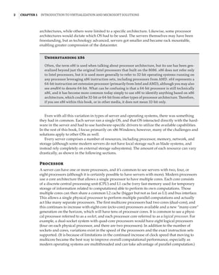
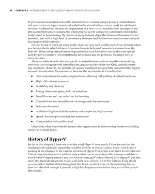
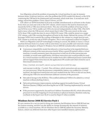
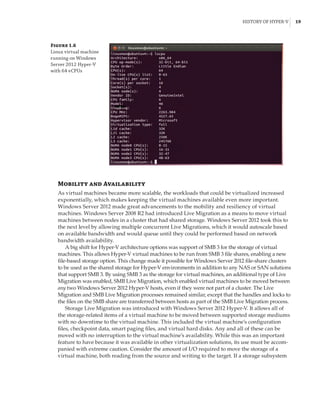
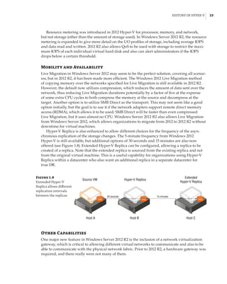
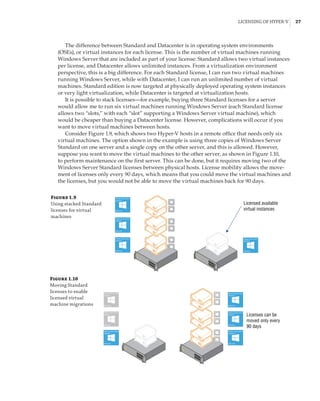
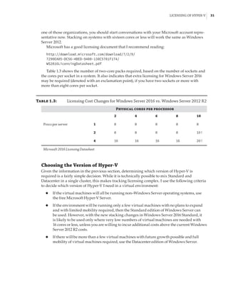
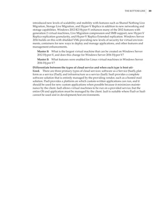
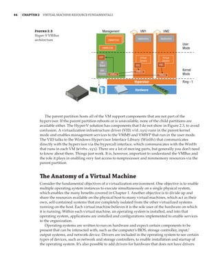
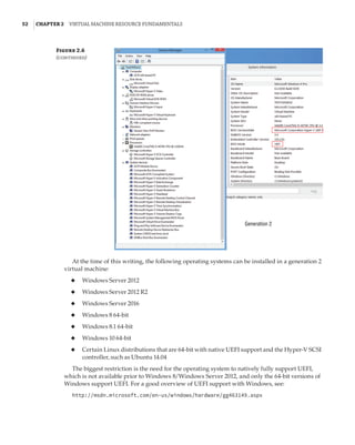
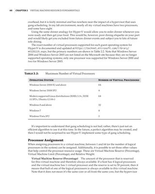
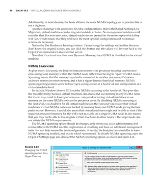
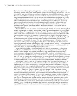
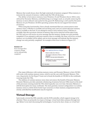
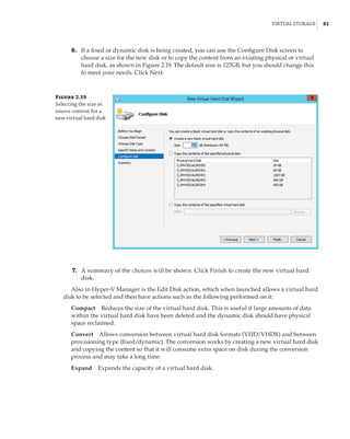
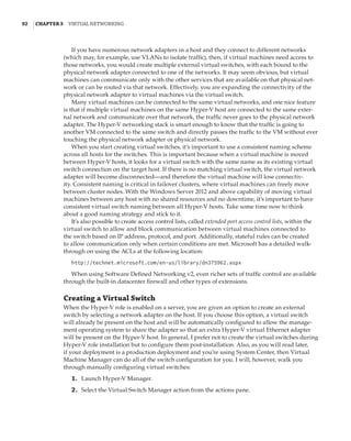
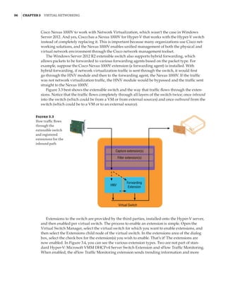
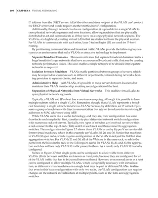
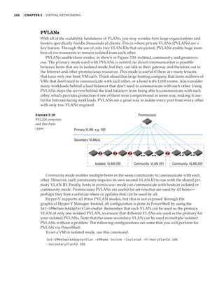
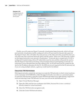
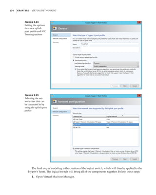
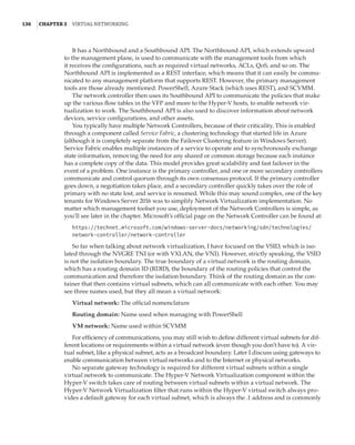
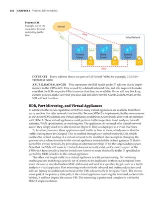
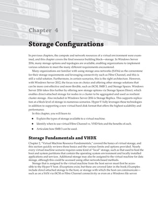
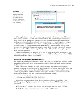
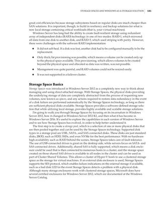
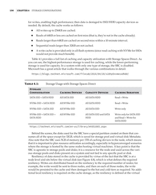
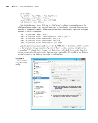
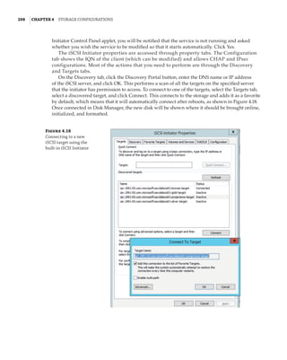
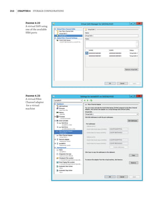
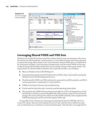
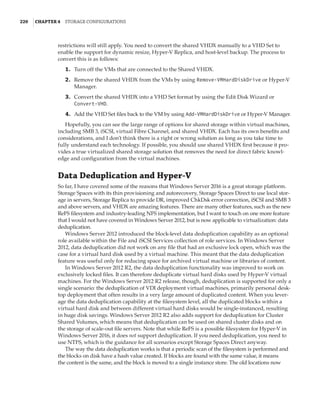
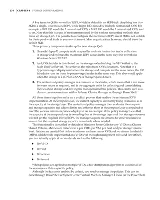
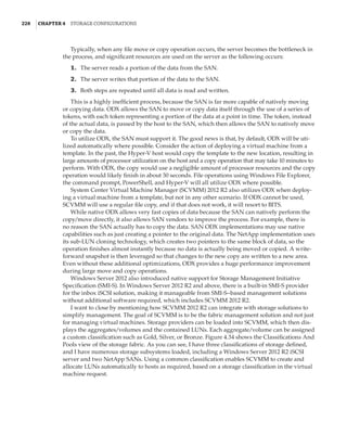
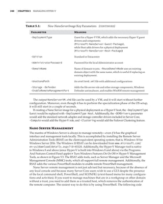
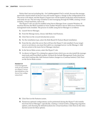
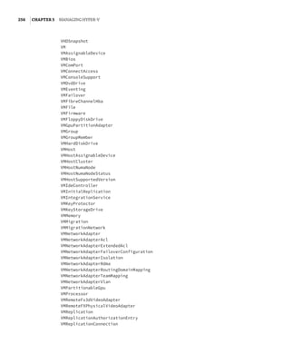
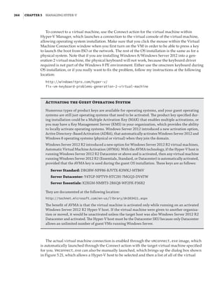
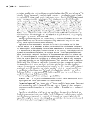
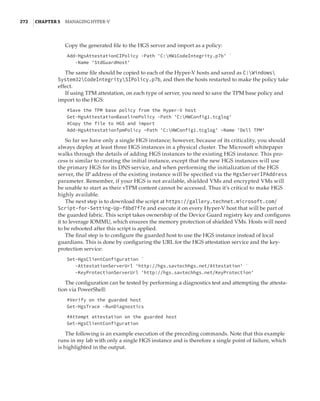
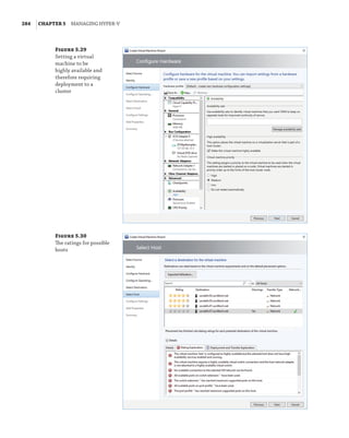
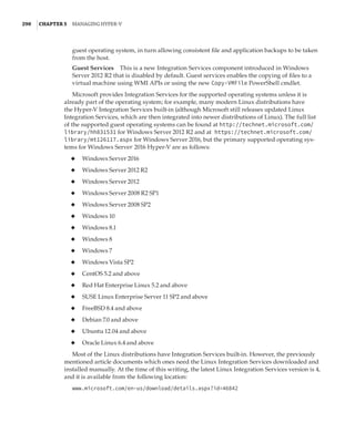
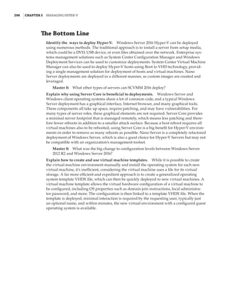
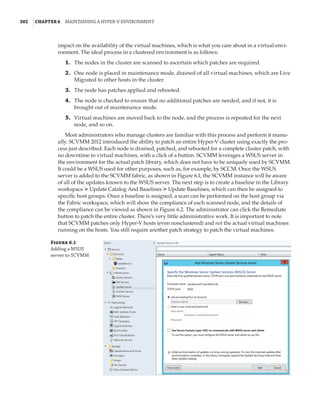
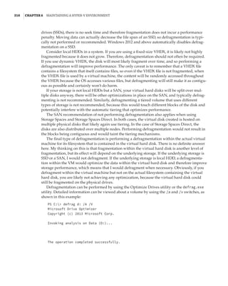
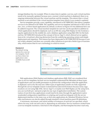
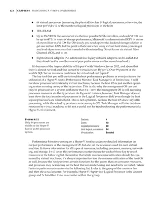
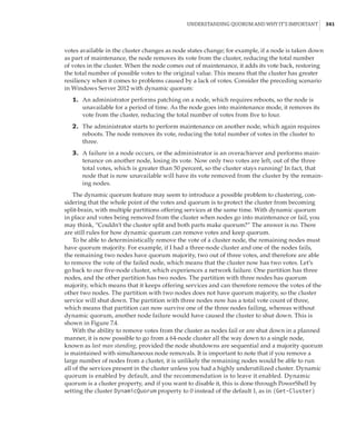
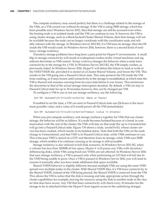
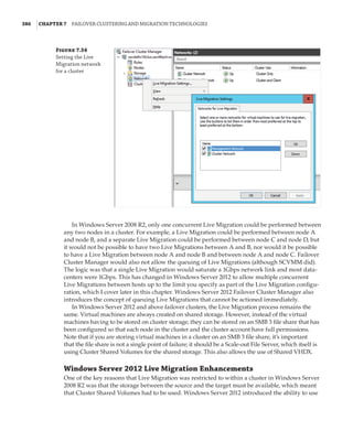
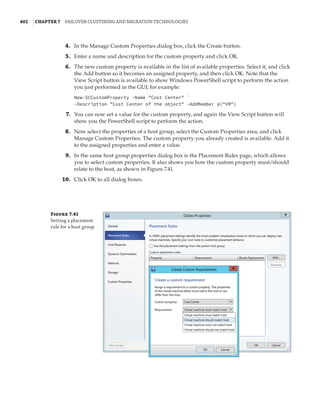
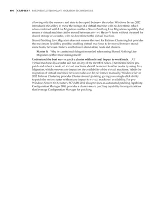
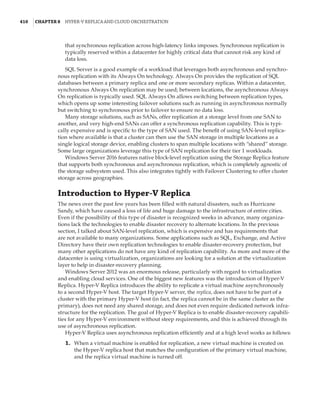
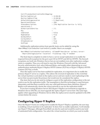
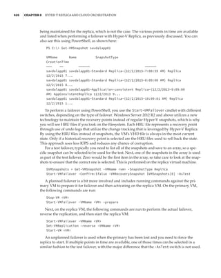
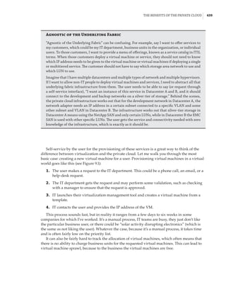
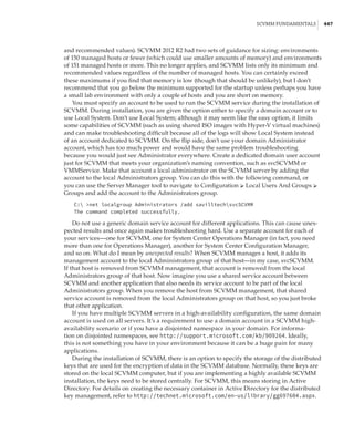
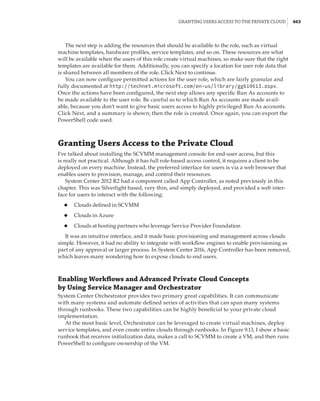
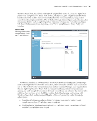
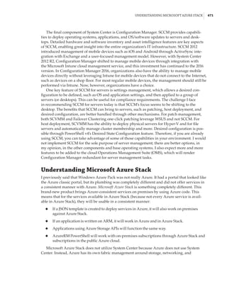
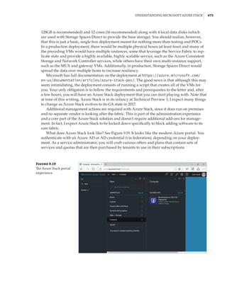
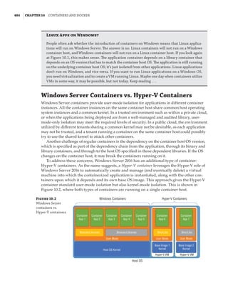
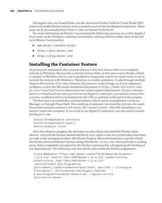
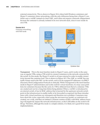
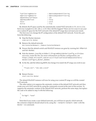
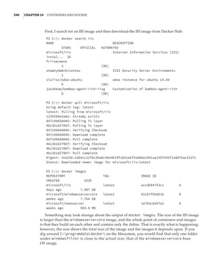
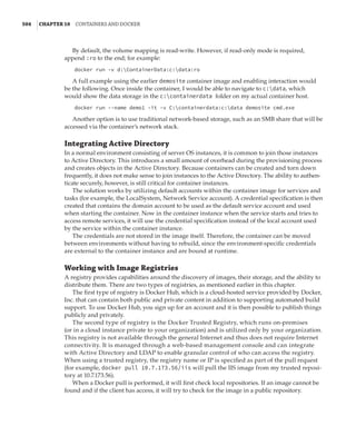
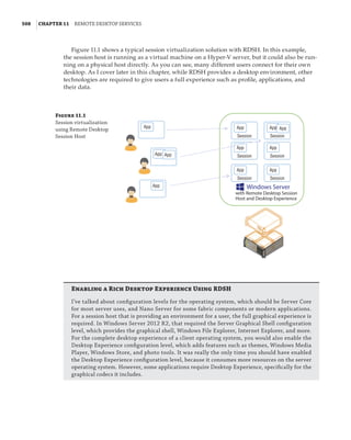
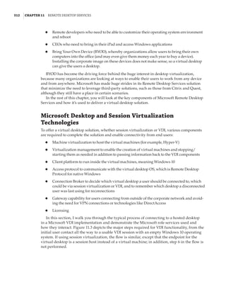
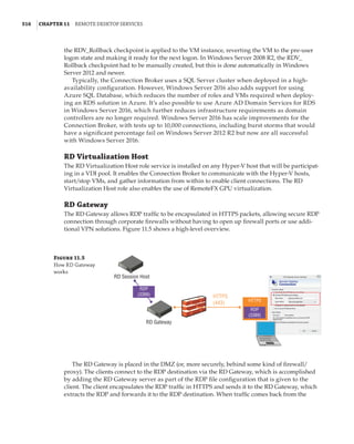
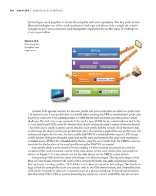
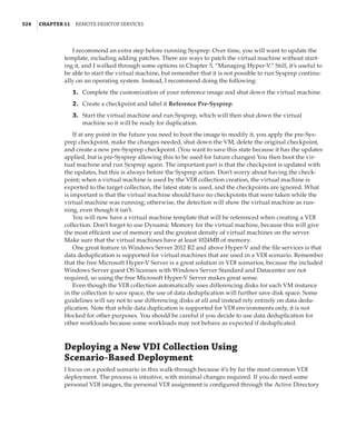
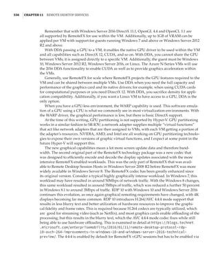
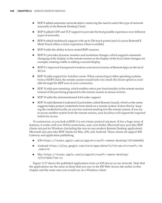
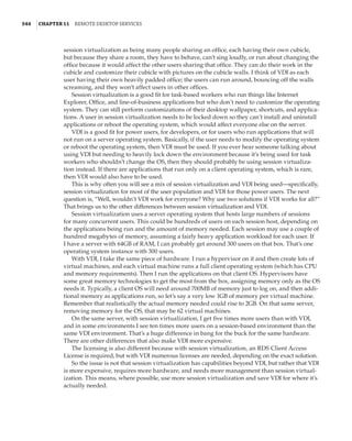
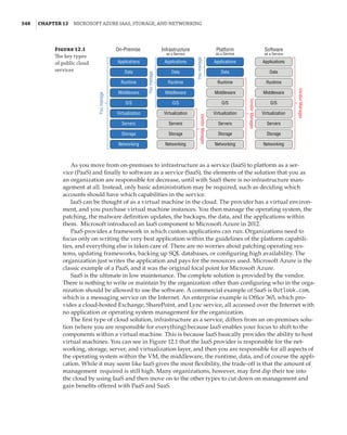
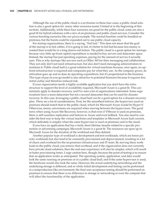
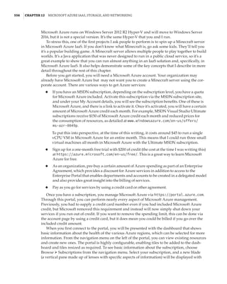
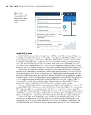
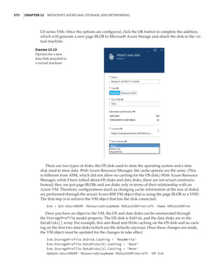
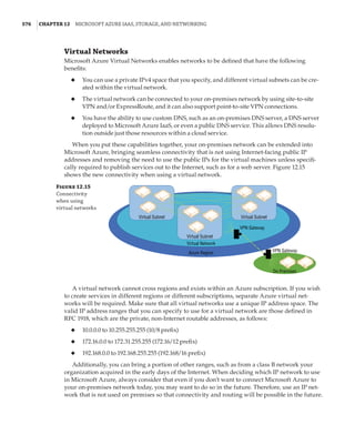
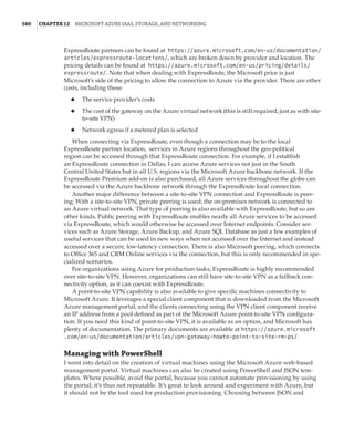
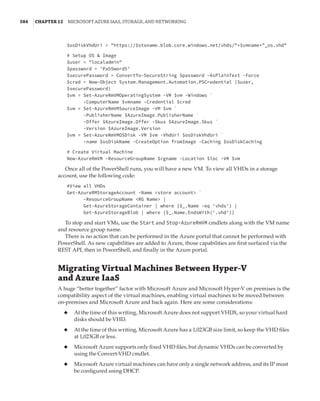
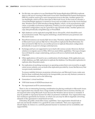
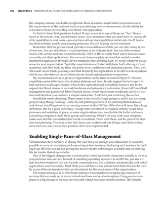
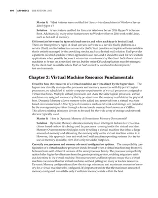
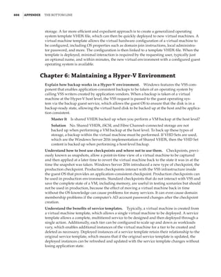
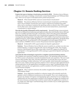
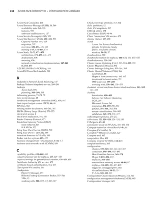
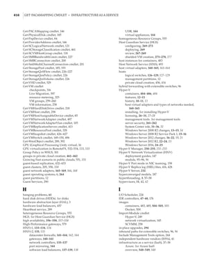
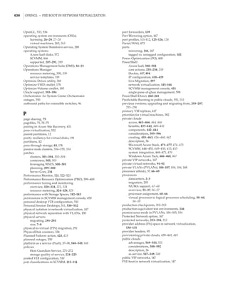
Figure 1.4
Hyper-V architecture
Hypervisor
Hardware
Management VM1 VM2
Ring 3
Ring 0
Ring –1
Application
Application
Application
Kernel Kernel Kernel
Application
Application
Application
Application
Application
Application
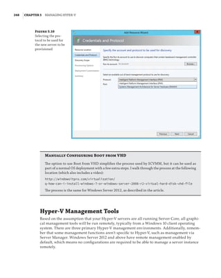
What Is a Partition?
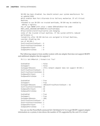
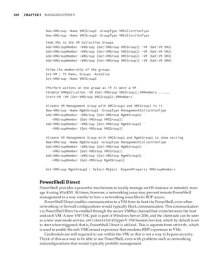
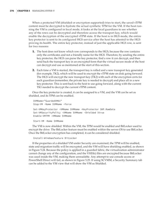
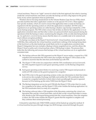
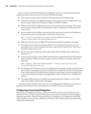
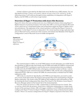
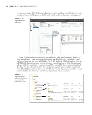
In the discussion of the history of Hyper-V, I referred to a management partition. The hypervisor
runs directly on the hardware and assigns different amounts of resources to each virtual environ-
ment. These virtual environments can also be referred to as partitions, because they are parti-
tions of the underlying resource. Because the management partition is not a true virtual machine
(because not all of its resources are virtualized) and it has privileged access, it is referred to as the
management partition or the parent partition. Although it can be confusing, it’s also common to see
the management partition referred to as the host because it is the OS closest to the hardware and
is directly installed on the server. Sometimes virtual machines are referred to as child partitions
or guest partitions.](https://image.slidesharecdn.com/masteringwindowshyper-v-2016-220718185053-392ce9da/85/Mastering-Windows-Hyper-V-2016-pdf-36-320.jpg)


![Virtual Storage | 85
SCSIAdapter} | Where-Object {$_.Service -eq stornvme}
# cycle through them disabling and dismounting them
foreach ($pnpdev in $pnpdevs)
{
disable-pnpdevice -InstanceId $pnpdev.InstanceId -Confirm:$false
$locationpath = ($pnpdev | get-pnpdeviceproperty ↵
DEVPKEY_Device_LocationPaths).data[0]
dismount-vmhostassignabledevice -locationpath $locationpath
$locationpath
}
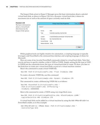
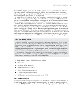
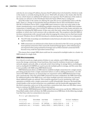
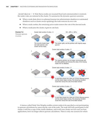
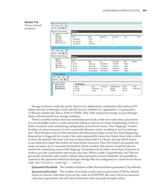
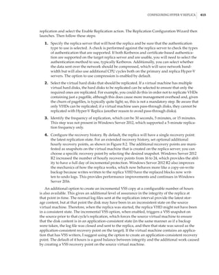
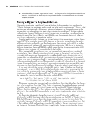
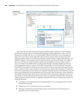
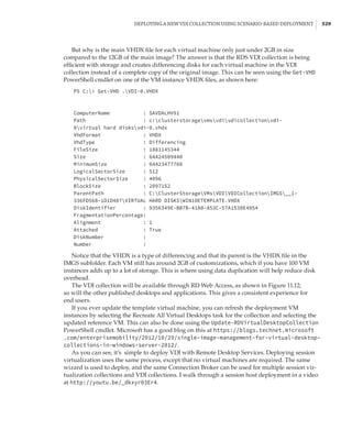
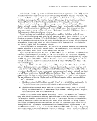
The output of the script will include the devices that were identified and unmounted. These
devices can also now be seen by executing the Get-VMHostAssignableDevice cmdlet, which
includes a property named LocationPath. It is the LocationPath that you specify when map-
ping a device to a VM via DDA using the Add-VMAssignableDevice cmdlet, for example:
PS C: Get-VMHostAssignableDevice
InstanceID : PCIPVEN_144DDEV_A820SUBSYS_1F951028REV_034368722DD00010
LocationPath : PCIROOT(40)#PCI(0200)#PCI(0000)
CimSession : CimSession: .
ComputerName : SAVDALHVFX
IsDeleted : False
PS C: Add-VMAssignableDevice -LocationPath ↵
PCIROOT(40)#PCI(0200)#PCI(0000) -VMName TestVM
To remove a device from a VM, use Remove-VMAssignableDevice with the same parameters
as the Add cmdlet. There is no graphical interface to manage DDA—you must use PowerShell.
Remember that since this is direct mapping of a device to a VM, if special drivers are needed for
the hardware, these will need to be installed in the VM guest OS, and you will no longer be able
to live-migrate the VM.
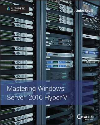
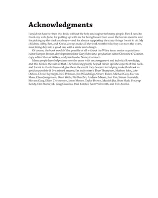
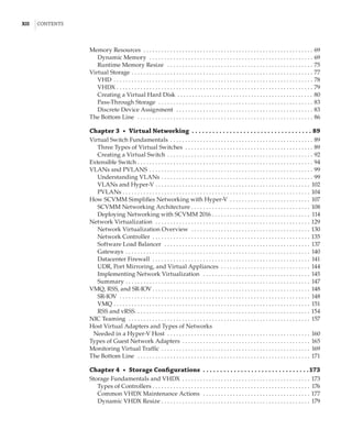
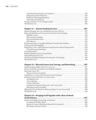
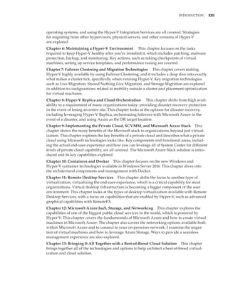
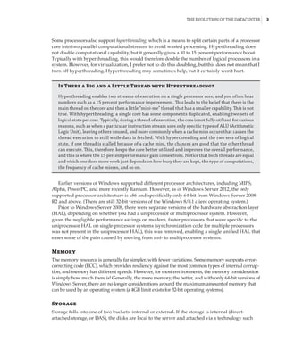
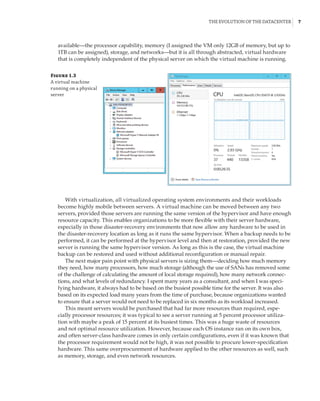
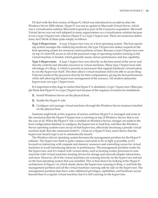
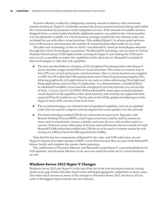
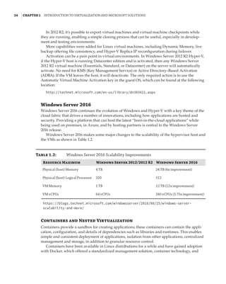
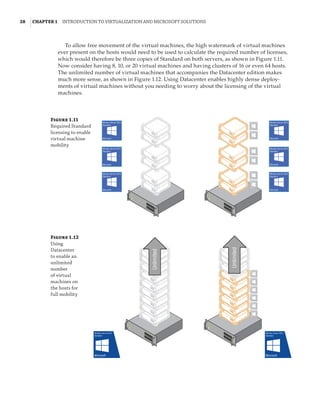
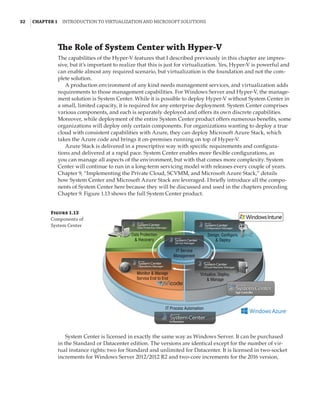
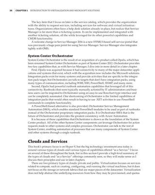
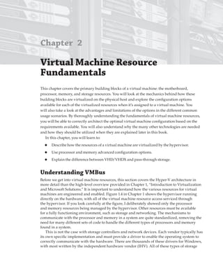
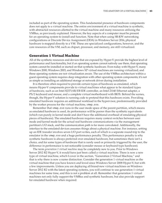
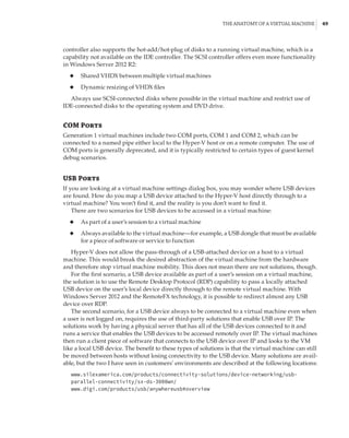
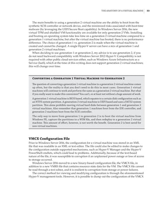
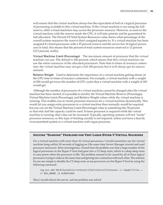
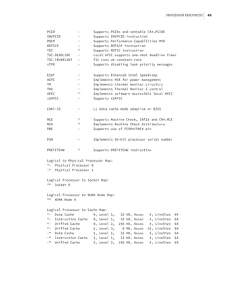
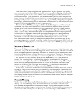
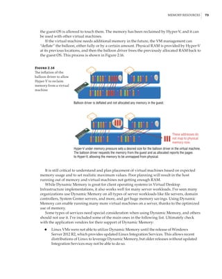
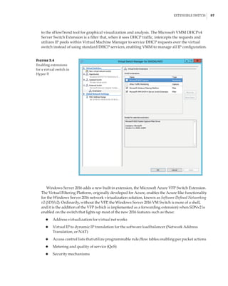
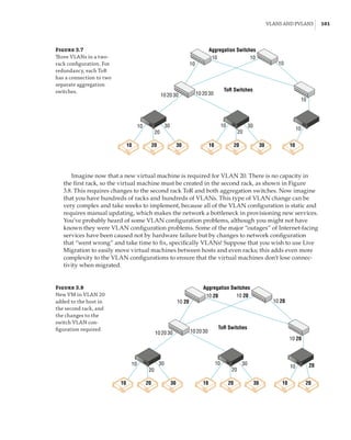
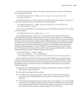
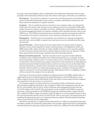
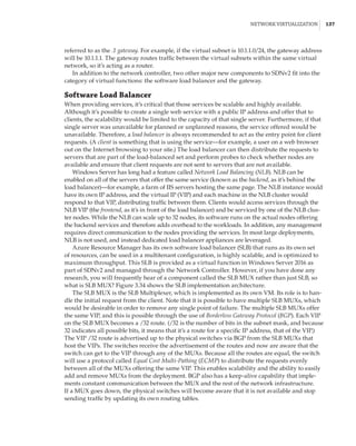
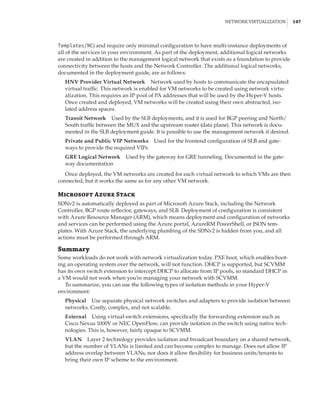
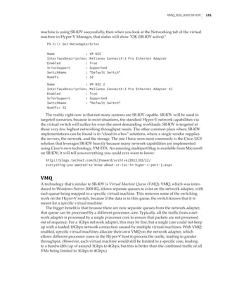
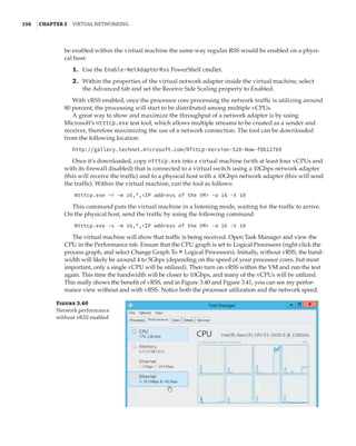
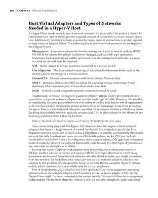
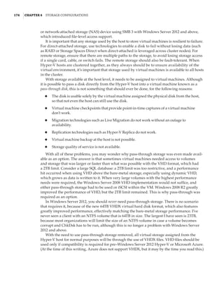
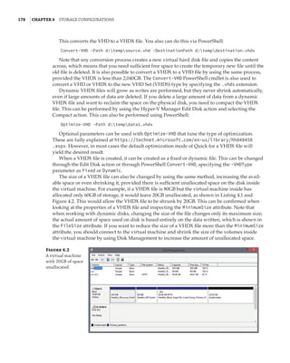
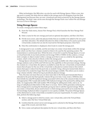
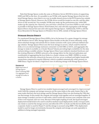
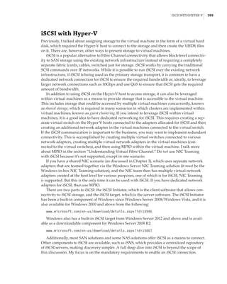
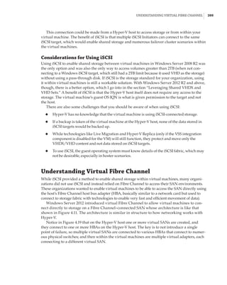
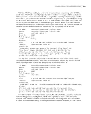
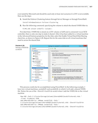
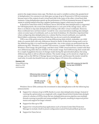
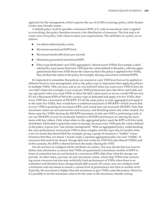
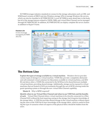
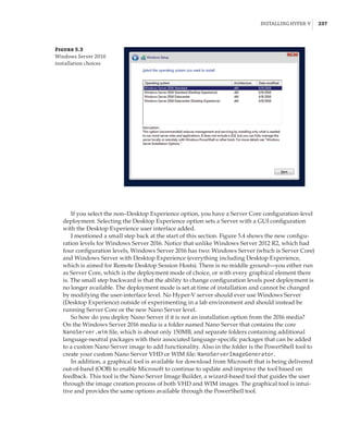
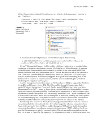
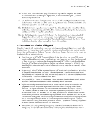
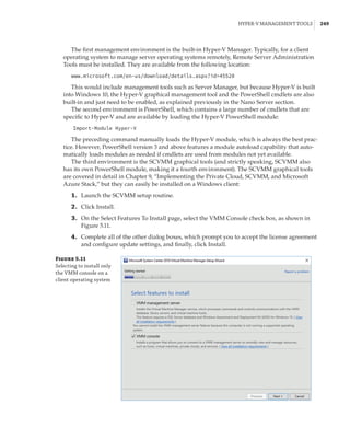
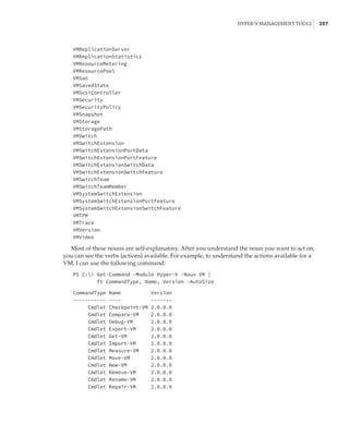
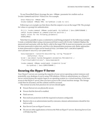
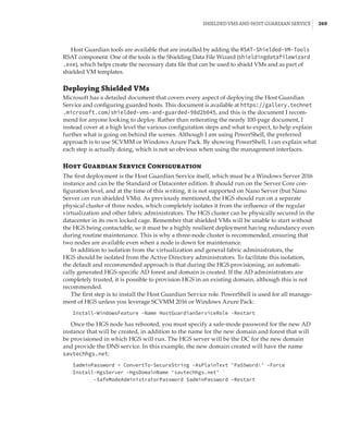
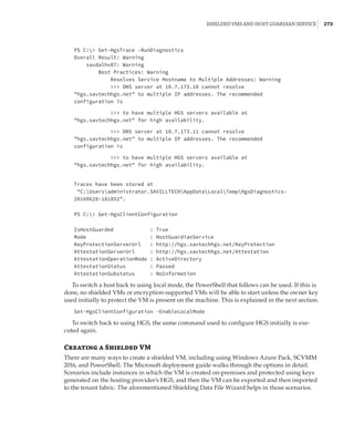
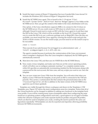
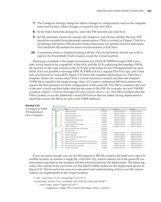
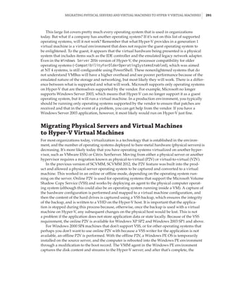
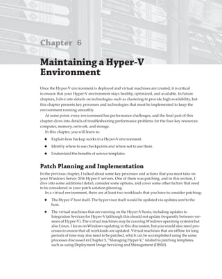
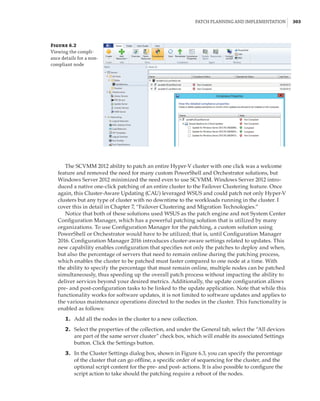
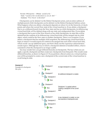
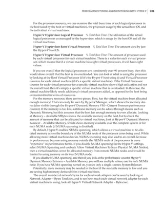
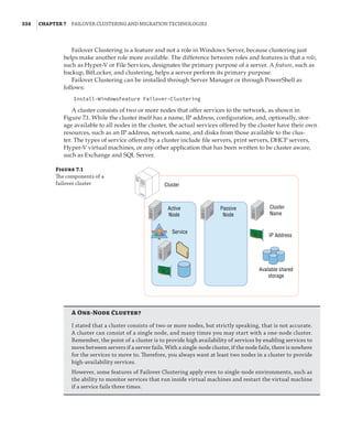
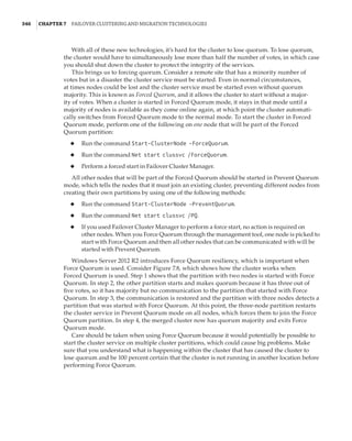
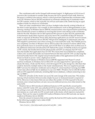
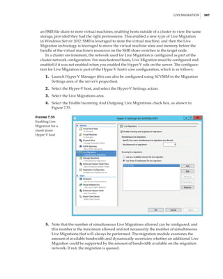
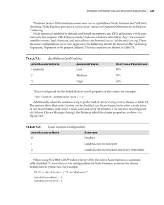
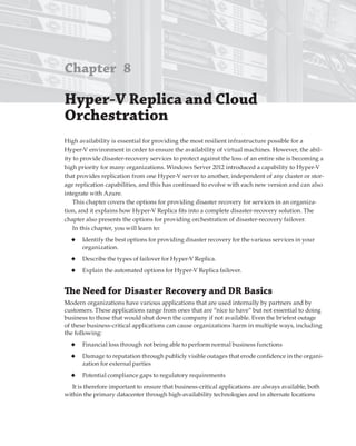
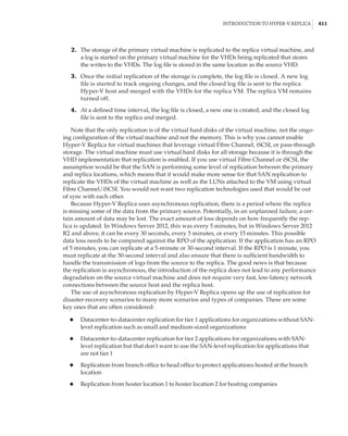
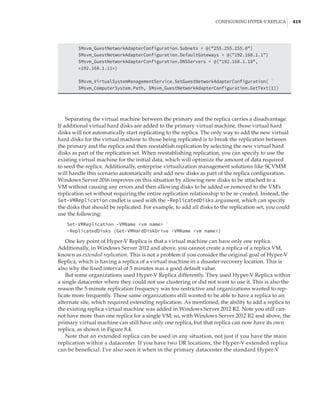
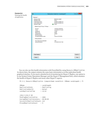
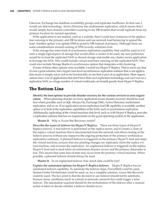
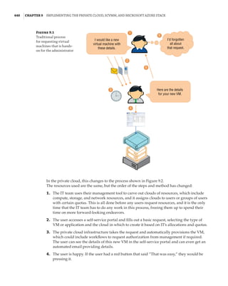
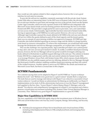
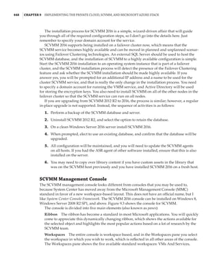
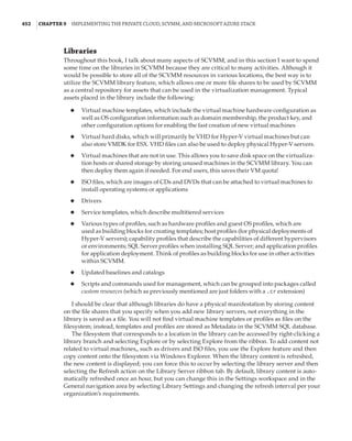
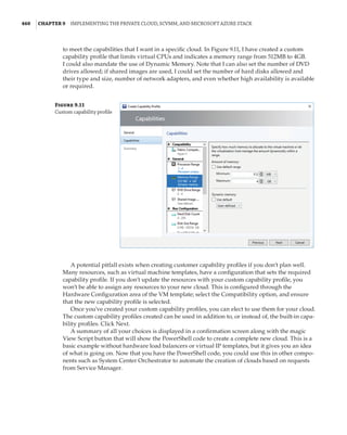
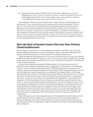
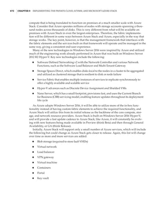
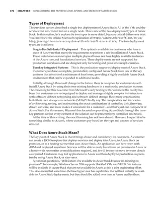
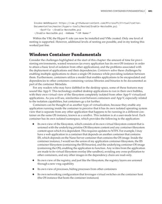
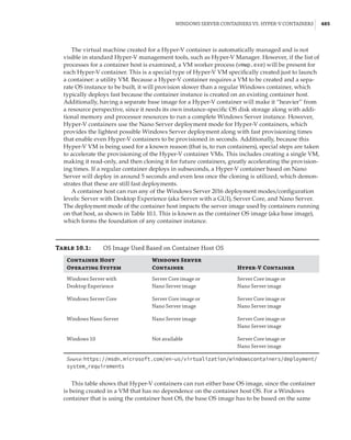
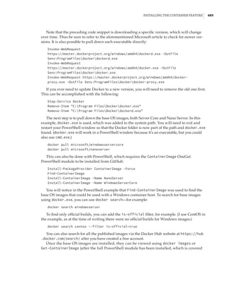
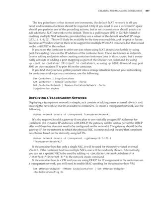
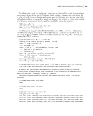
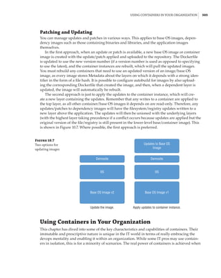
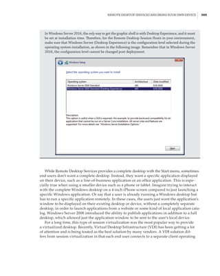
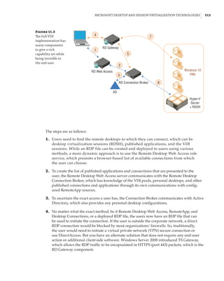
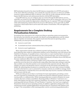
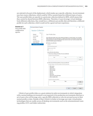
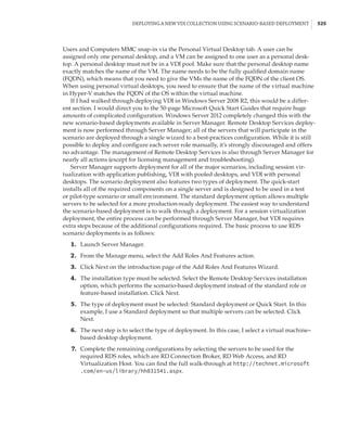
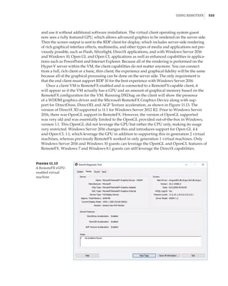
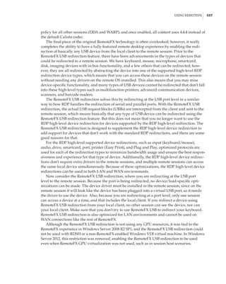
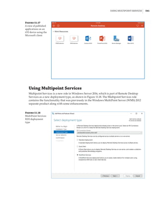
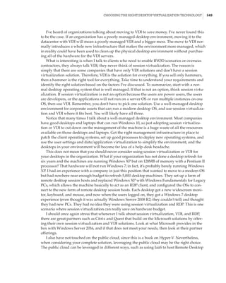
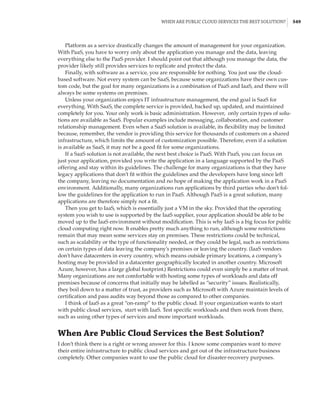
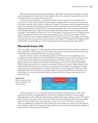
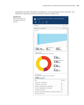
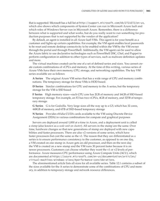
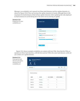
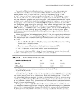
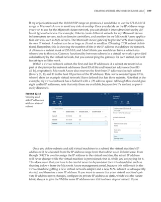
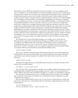
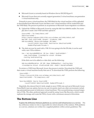
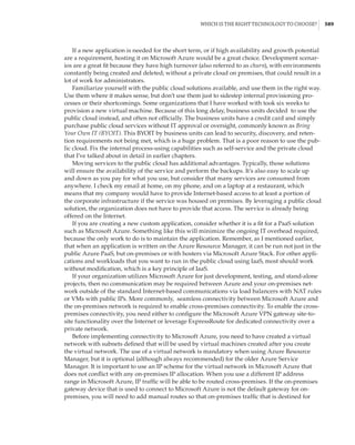
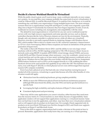
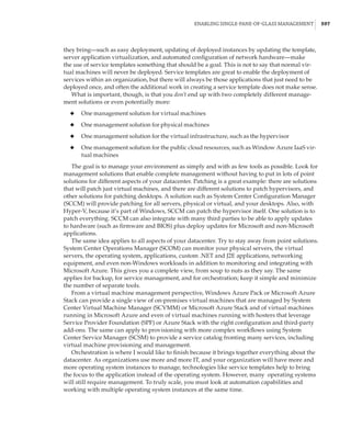
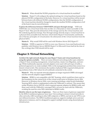
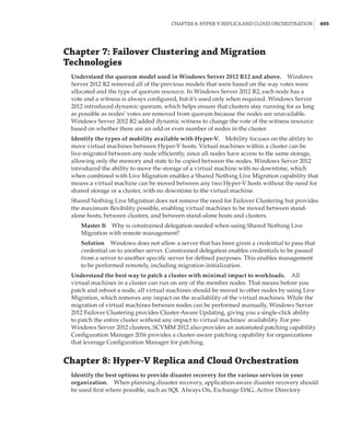
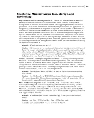
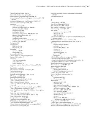
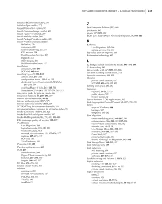
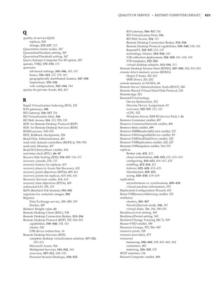
When mapping an NVMe storage device to a VM using DDA, no additional configura-
tion is required. However, if you are mapping a graphics device that tends to have a lot of
memory, memory-mapped I/O space will not be available for the guest OS to map
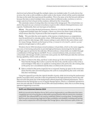
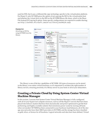
and use the memory of the graphical device. You will need to reconfigure the VM. The
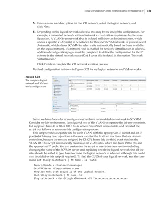
exact amount of memory that needs to be mapped will depend on the graphics device, and
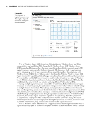
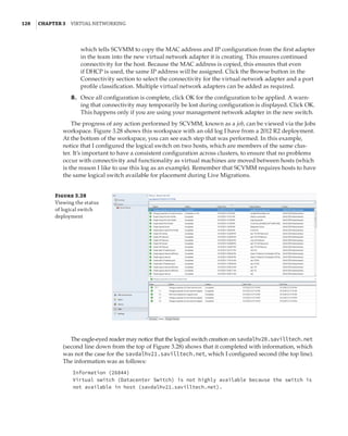
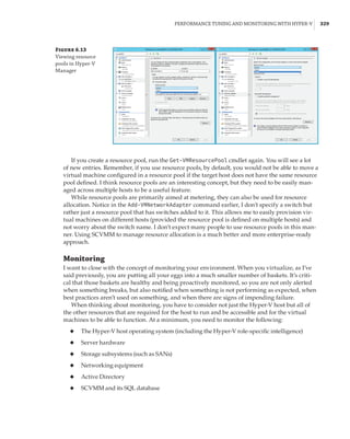
it can be seen by examining the Resources tab of the device in Device Manager, as shown
in Figure 2.21. You can modify the low and high memory space for VMs by using the -
LowMemoryMappedIoSpace and -HighMemoryMappedIoSpace parameters of the Set-VM
cmdlet. This is explained in detail in this article:
https://blogs.technet.microsoft.com/virtualization/2015/11/23/
discrete-device-assignment-gpus/
The article also points out that you should enable the guest to control the caching by setting
-GuestControlledCacheTypes $true via Set-VM. All of these configurations require the VM to
be shut down.](https://image.slidesharecdn.com/masteringwindowshyper-v-2016-220718185053-392ce9da/85/Mastering-Windows-Hyper-V-2016-pdf-109-320.jpg)


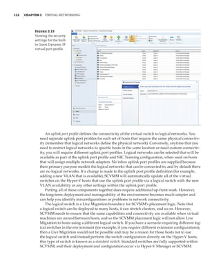
![Network Virtualization | 145
Implementing Network Virtualization
In my 2012 R2 version of this book, I walked step by step through deploying network virtu-
alization and deploying a gateway. SDNv2, however, is different. There are three primary
management planes, and the method of implementing the virtual network, gateway, SLB,
datacenter firewall, UDR, and so on is different. It is also likely to change over time, especially
with SCVMM and Microsoft Azure Stack, so any specific instructions likely would become anti-
quated quickly. Thus, for exact details, I recommend reviewing the Microsoft documents, which
are thorough. Nonetheless, I want to cover the experience briefly when using the three manage-
ment planes. Remember, after you pick one, you must continue using it—you cannot switch—
with the exception of leveraging PowerShell to configure UDR and mirroring if using SCVMM.
PowerShell
PowerShell cmdlets are built into Windows Server 2016, and a manual deployment of every
component is possible, which is documented at https://technet.microsoft.com/en-us/
library/mt282165.aspx. The better option, however, is to use SDNExpress. SDNExpress is a
script with accompanying files that is downloaded from GitHub (so it can be updated). Execute
the script, and after about 30 minutes, you will have a completely deployed SDNv2 environment
including the following:
◆
◆ Distributing required certificates
◆
◆ Multi-instance Network Controller deployment
◆
◆ Configuration of Network Controller via REST API
◆
◆ All Hyper-V host networking including VFP and host agents deployed
◆
◆ Multitenant gateway deployed and configured
Information about SDNExpress can be found at https://technet.microsoft.com/en-us/
library/mt427380.aspx and can be downloaded from https://github.com/Microsoft/SDN.
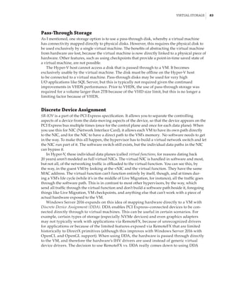
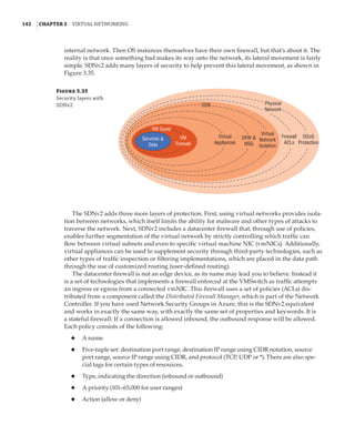
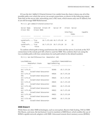
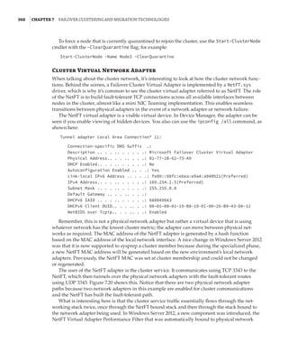
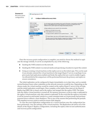
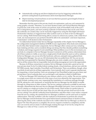
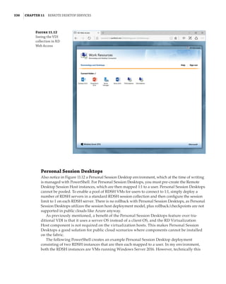
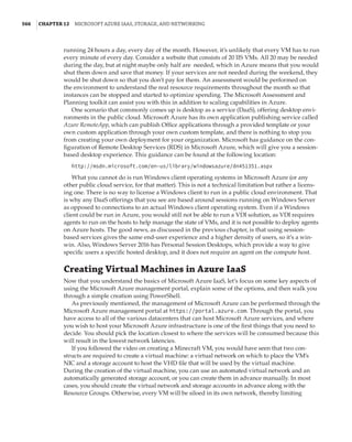
Once deployed, the various *-NetworkController* cmdlets are used to communicate with the
Network Controller and perform configuration. For example, you can use the following to con-
nect to a network controller, get the object for a virtual network, and then view all ACLs known:
Import-Module networkcontroller
$URI = https://savdalnc01.savilltech.net
# Grab the Resource Id of the first Virtual Network
(Get-NetworkControllerVirtualNetwork -ConnectionUri $uri)[0] `
|fl ResourceId
ResourceId : 7fb0a029-136d-44cd-8697-8dbcac7a7c70
# Grab all Virtual Subnets attached to the above Virtual Network
Get-NetworkControllerVirtualSubnet -ConnectionUri $uri `
-VirtualNetworkId 7fb0a029-136d-44cd-8697-8dbcac7a7c70
# Check for ACLs applied to a virtual subnet
Get-NetworkControllerVirtualSubnet -ConnectionUri $uri `
-VirtualNetworkId 7fb0a029-136d-44cd-8697-8dbcac7a7c70 `](https://image.slidesharecdn.com/masteringwindowshyper-v-2016-220718185053-392ce9da/85/Mastering-Windows-Hyper-V-2016-pdf-169-320.jpg)
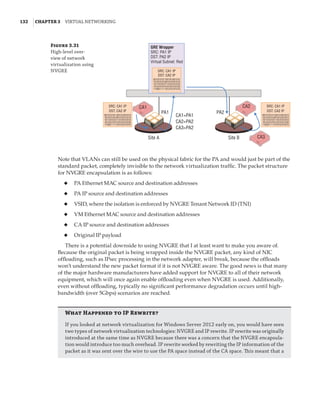
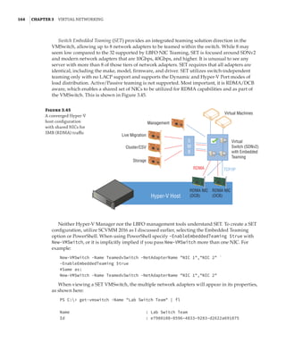
![146 |Chapter 3 Virtual Networking
| foreach { $_.Properties.AccessControlList }
Get-NetworkControllerNetworkInterface -ConnectionUri $uri `
| foreach { $_.Properties.IpConfigurations.Properties.AccessControlList }
$acl = Get-NetworkControllerAccessControlList -ConnectionUri $uri `
-ResourceId f8b97a4c-4419-481d-b757-a58483512640
$acl.Properties.AclRules[0].Properties
If you experience problems with the Network Controller, I recommend several useful
PowerShell cmdlets for debugging:
◆
◆ Debug-NetworkController: Information about the Network Controller
◆
◆ Debug-NetworkControllerConfigurationState: Configuration state of a Network
Controller
◆
◆ Debug-ServiceFabricNodeStatus: Health of a Network Controller
◆
◆ Get-NetworkControllerDeploymentInfo: Deployment information of a Network Controller
◆
◆ Get-NetworkControllerReplica: Replica information for a Network Controller
◆
◆ Get-CustomerRoute: Routing information
◆
◆ Get-PACAMapping: Mapping between PA and CA
◆
◆ Get-ProviderAddress: Information about provider addresses
◆
◆ Test-VirtualNetworkConnection: Perform a test to a virtual network.
There are many others. Use (Get-Module HNVDiagnostics).ExportedCommands to see a
full list.
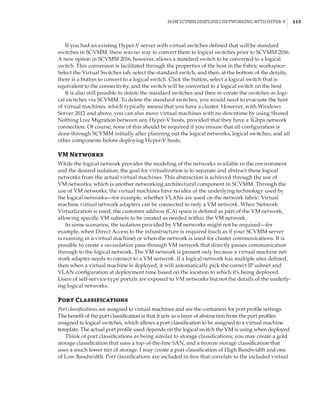
System Center Virtual Machine Manager
The core logical network, logical switch, VM network, and other fabric components are all used
for the SCVMM deployment of SDNv2, and they have a step-by-step guide for the following:
◆
◆ Deployment of Network Controller and the basic virtual networks:
https://technet.microsoft.com/system-center-docs/vmm/Manage/
Deploy-a-Network-Controller-using-VMM
◆
◆ Deployment of SLB:
https://technet.microsoft.com/en-us/system-center-docs/vmm/manage/
deploy-a-software-load-balancer-using-vmm:
◆
◆ Deployment of gateway:
https://technet.microsoft.com/system-center-docs/vmm/Manage/
Deploy-a-RAS-Gateway-using-VMM
You need to provide a VM template, which should be Windows Server 2016 Datacenter, and
can be either Server Core or Server with Desktop Experience. Where possible, I recommend
using Server Core.
These deployments are all facilitated through the use of service templates, which are avail-
able for download from GitHub (https://github.com/Microsoft/SDN/tree/master/VMM/](https://image.slidesharecdn.com/masteringwindowshyper-v-2016-220718185053-392ce9da/85/Mastering-Windows-Hyper-V-2016-pdf-170-320.jpg)
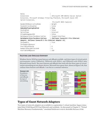
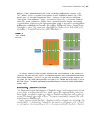
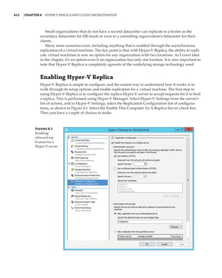
![VMQ, RSS, and SR-IOV | 155
Enabled : True
NumberOfReceiveQueues : 4
Profile : NUMAStatic
BaseProcessor: [Group:Number] : 0:0
MaxProcessor: [Group:Number] : 0:30
MaxProcessors : 16
RssProcessorArray: [Group:Number/NUMA Distance]:
0:0/0 0:2/0 0:4/0 0:6/0 0:8/0 0:10/0 0:12/0 0:14/0
0:16/0 0:18/0 0:20/0 0:22/0 0:24/0 0:26/0 0:28/0 0:30/0
IndirectionTable: [Group:Number]:
0:4 0:20 0:6 0:22 0:4 0:20 0:6 0:22
0:4 0:20 0:6 0:22 0:4 0:20 0:6 0:22
0:4 0:20 0:6 0:22 0:4 0:20 0:6 0:22
0:4 0:20 0:6 0:22 0:4 0:20 0:6 0:22
0:4 0:20 0:6 0:22 0:4 0:20 0:6 0:22
0:4 0:20 0:6 0:22 0:4 0:20 0:6 0:22
0:4 0:20 0:6 0:22 0:4 0:20 0:6 0:22
0:4 0:20 0:6 0:22 0:4 0:20 0:6 0:22
0:4 0:20 0:6 0:22 0:4 0:20 0:6 0:22
0:4 0:20 0:6 0:22 0:4 0:20 0:6 0:22
0:4 0:20 0:6 0:22 0:4 0:20 0:6 0:22
0:4 0:20 0:6 0:22 0:4 0:20 0:6 0:22
0:4 0:20 0:6 0:22 0:4 0:20 0:6 0:22
0:4 0:20 0:6 0:22 0:4 0:20 0:6 0:22
0:4 0:20 0:6 0:22 0:4 0:20 0:6 0:22
0:4 0:20 0:6 0:22 0:4 0:20 0:6 0:22
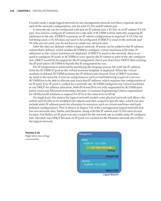
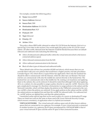
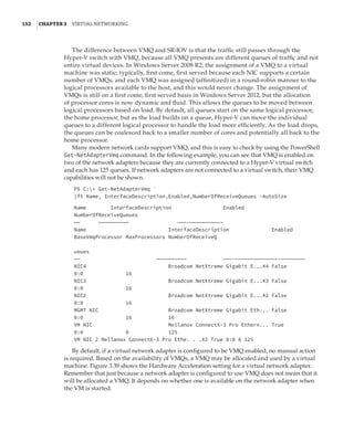
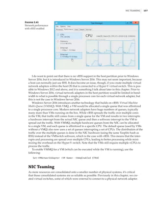
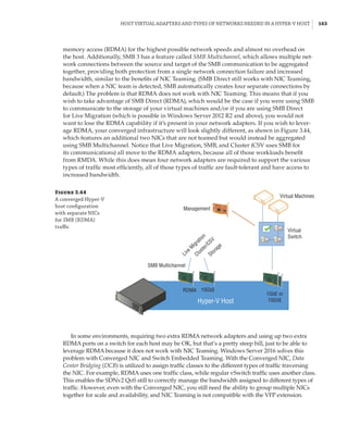
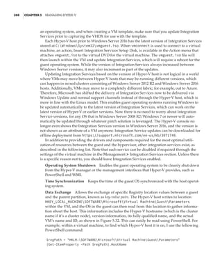
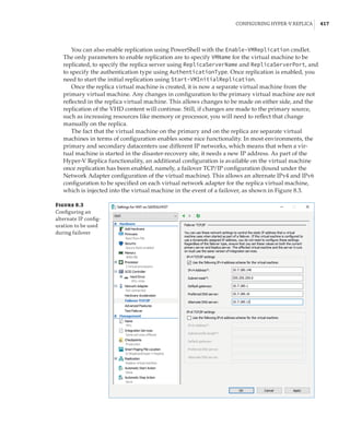
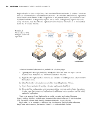
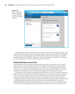
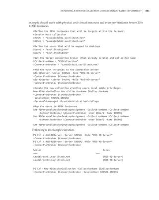
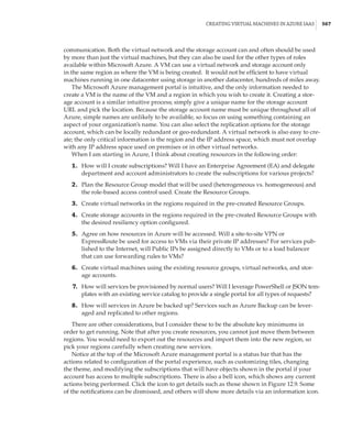
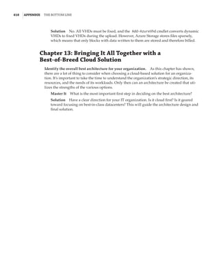
It’s possible to configure the processor cores to be used for an RSS adapter by modifying the
BaseProcessorNumber, MaxProcessorNumber, and MaxProcessors values by using the
Set-NetAdapterRss PowerShell cmdlet. This gives the administrator more-granular con-
trol of the processor resources used to process network traffic. It’s also possible to enable
and disable RSS for specific network adapters by using Enable-NetAdapterRss and
Disable-NetAdapterRss.
RSS is a great technology, but it is disabled as soon as a network adapter is connected to a
virtual switch. VMQ and RSS are mutually exclusive: You do not get the benefit of RSS for vir-
tual network adapters connected to virtual machines. Therefore, if you have a virtual switch
connected to a 10Gbps NIC, the throughput to a virtual machine is only around 3 to 4Gbps,
the maximum amount a single processor core can process, and this is what was possible with
Windows Server 2012. This changes with Windows Server 2012 R2 and the introduction of vir-
tual RSS, or vRSS.
vRSS enables the RSS mechanism to split incoming packets between multiple virtual proces-
sors within the virtual machine. A virtual machine can now leverage the full bandwidth avail-
able; for example, a virtual machine can now receive 10Gbps over its virtual NIC, because the
processing is no longer bottlenecked to a single virtual processor core.
For vRSS, the network adapter must support VMQ. The actual RSS work is performed on the
Hyper-V host within the Hyper-V switch. Therefore, using vRSS does introduce some additional
CPU load on the host, which is why, by default, vRSS is disabled in the virtual machine. It must](https://image.slidesharecdn.com/masteringwindowshyper-v-2016-220718185053-392ce9da/85/Mastering-Windows-Hyper-V-2016-pdf-179-320.jpg)


![192 |Chapter 4 Storage Configurations
available and can be used to replace corrupt copies that were automatically detected. ReFS enabled
online backup and repair of its critical Metadata. It was common to use ReFS for long-term archival
data requiring high levels of resiliency. When using ReFS, you should use it on Storage Spaces for the
best resiliency possible. However, using Storage Spaces does not imply that you need to use ReFS.
In Windows Server 2012 and Windows Server 2012 R2, ReFS was blocked as a storage media for
Hyper-V because its integrity stream feature (which enabled the healing ability) caused performance
problems with Hyper-V workloads. In Windows Server 2016, this block has been removed, as the
integrity stream performance has been improved and is disabled by default anyway.
Why use ReFS beyond resiliency? NTFS was designed a long time ago, when disks were much
smaller. It focused all of its effort on blocks on disk, which means that when you deal with large
numbers of blocks, even on superfast storage, the operations still take a long time. ReFS shifts
this focus to thinking about Metadata manipulation before block manipulation, where possible.
For example, when a new fixed VHD file is created on NTFS, all of the blocks are zeroed on disk,
requiring huge amounts of zeroing I/O. With ReFS, this zeroing I/O is completely eliminated. There
is no loss of security related to reading existing data on disk. With ReFS, it is not possible to read
from noninitialized clusters on disks, which means that even though the extents backing the file
have been preallocated, they cannot be read from disk unless they have first been written to. The
same benefit applies to extending an existing VHD. The same Metadata manipulation applies when
merging differencing disks into the parent; for example, when merging a checkpoint. Instead of
copying the blocks from the differencing disk into the parent, the Metadata of the parent is updated
to point to the existing blocks on disk to which the differencing disk had written. Checkpoints
are now used for backups with Hyper-V in Windows Server 2016, which means that backup would
also benefit. These changes make the mentioned VHD operations hundreds, if not thousands, of
times faster than with NTFS, meaning faster provisioning and less I/O on the underlying storage.
Does this mean that ReFS is everywhere in Windows Server 2016? At the time of this writing, the
answer is no, although this could certainly change. Currently, ReFS cannot be the Windows boot
volume, it does not support the deduplication feature, and its broad use has not been a focus for
Microsoft. The focus for ReFS usage is with Storage Spaces Direct and where high levels of resiliency
are required. Outside of those scenarios, NTFS is still the recommended filesystem. Nonetheless,
when you consider the benefits it brings to Hyper-V and VHD files, it is certainly worth evaluat-
ing beyond just Storage Spaces Direct, provided you do not need data deduplication. Additionally,
when ReFS is used with Cluster Shared Volumes, the CSV will run in filesystem redirected mode,
which means all I/O is sent over the cluster network to the coordinator node. In NTFS, all nodes
can perform Direct I/O to the shared storage. This is a big reason to carry on using NTFS for CSV,
except for Storage Spaces Direct, which does not have shared storage anyway, and all access is
already redirected. What Microsoft has is a maturing filesystem that is now in its third version
with Windows Server 2016, and that is ready for the big time when a need requires its particular
talents, such as Storage Spaces Direct.
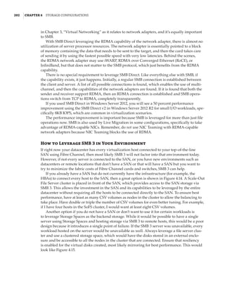
Using Storage Spaces Direct is simple, but it must be enabled at a cluster level, and once
it’s enabled, you will not be able to use clustered Storage Spaces. Management is done using
PowerShell or System Center Virtual Machine 2016. To enable Storage Spaces Direct, use the
following command:
Enable-ClusterS2D [-S2DPoolFriendlyName pool name]
continued](https://image.slidesharecdn.com/masteringwindowshyper-v-2016-220718185053-392ce9da/85/Mastering-Windows-Hyper-V-2016-pdf-216-320.jpg)
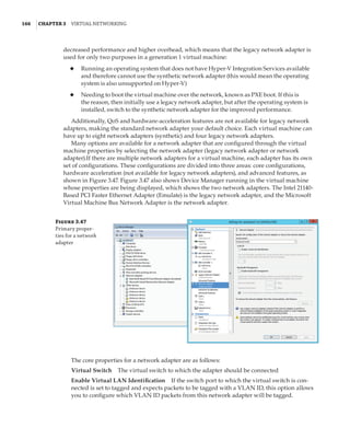
![Server Message Block Usage | 197
To set up Storage Replica using PowerShell, use the New-SRPartnership cmdlet with the
same parameters as Test-SRTopology. For example:
New-SRPartnership -SourceComputerName server -SourceRGName name `
-SourceVolumeName drive: -SourceLogVolumeName drive: `
-DestinationComputerName server -DestinationRGName name `
-DestinationVolumeName drive: -DestinationLogVolumeName drive: `
-LogSizeInBytes size, 8GB by default `
[-ReplicationMode Asynchronous, Synchronous is the default]
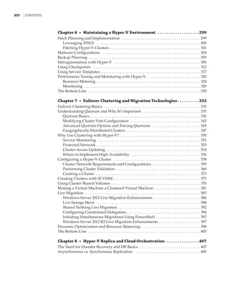
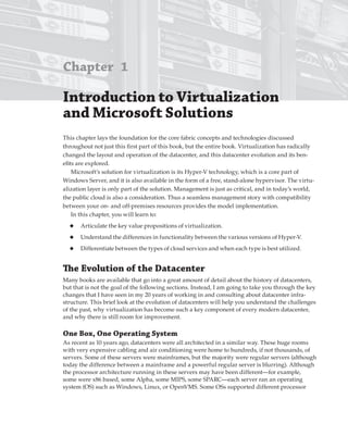
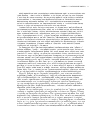
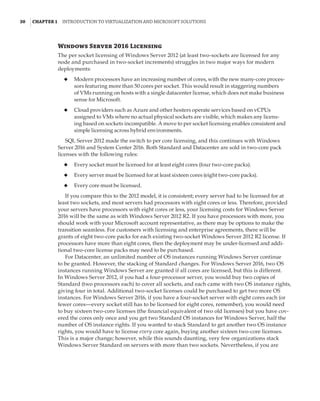
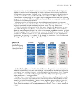
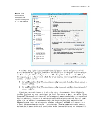
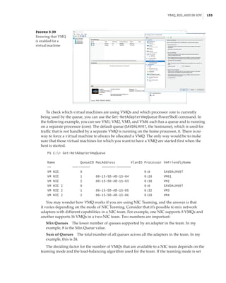
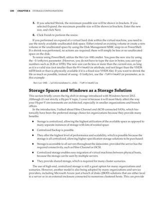
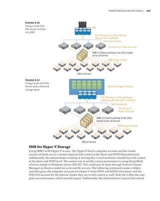
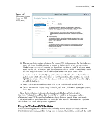
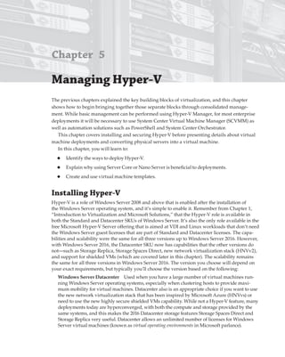
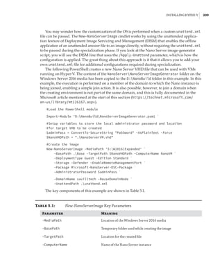
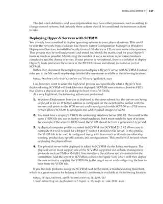
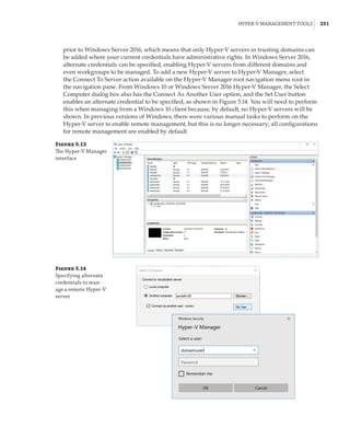
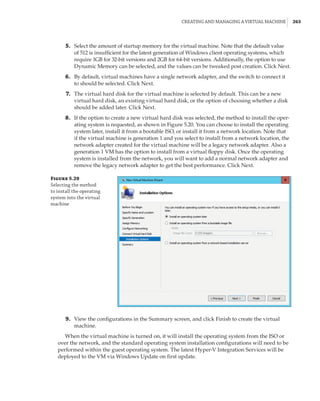
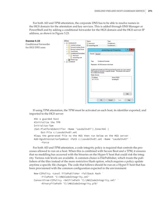
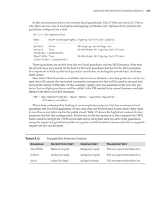
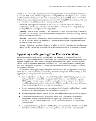
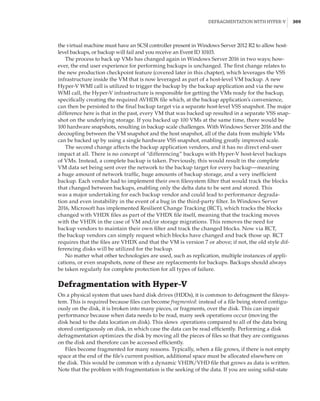
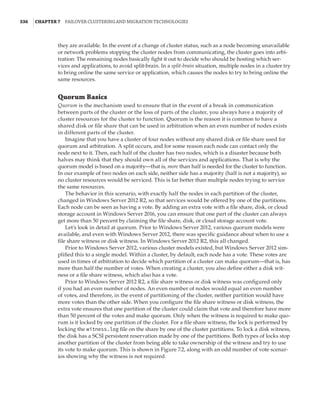
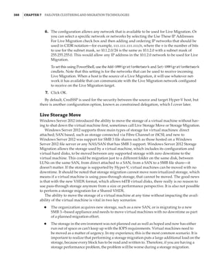
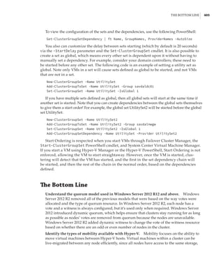
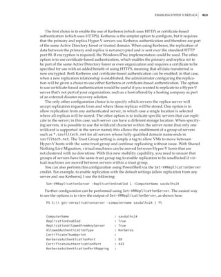
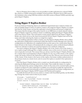
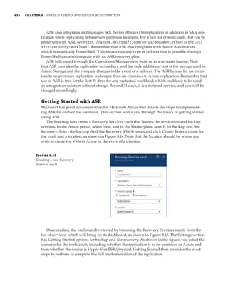
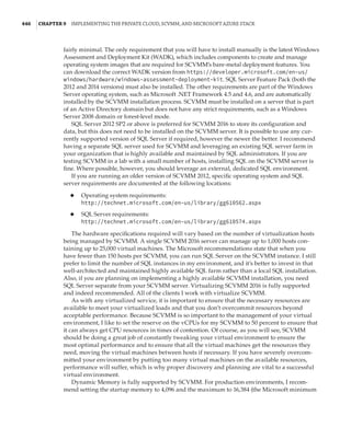
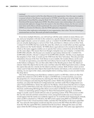
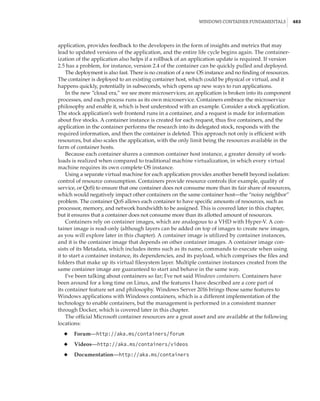
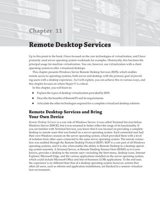
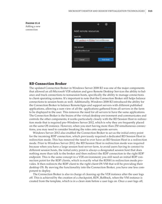
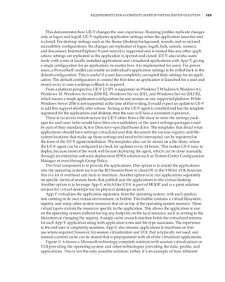
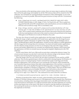
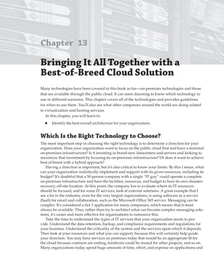
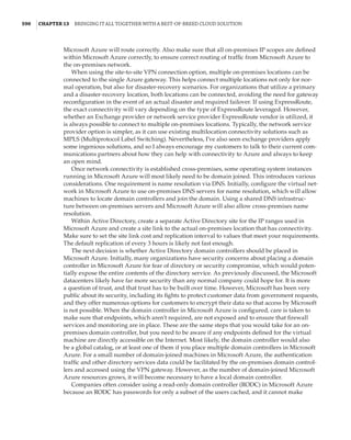
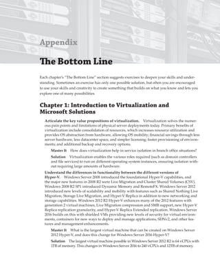
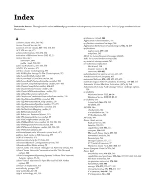
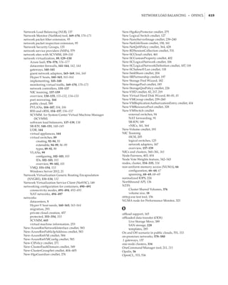
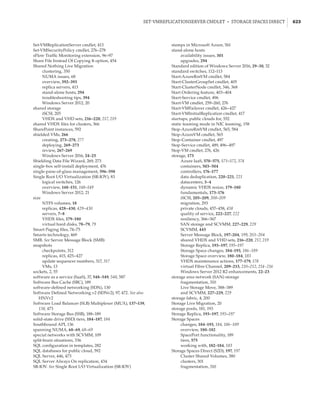
Storage Spaces Direct and Storage Replica Together
Storage Spaces Direct requires low latency, and it is based around nodes being in the same
datacenter. However, what if you want to use direct-attached storage in a stretched cluster
scenario? The solution is to combine Storage Spaces Direct and Storage Replica while utilizing
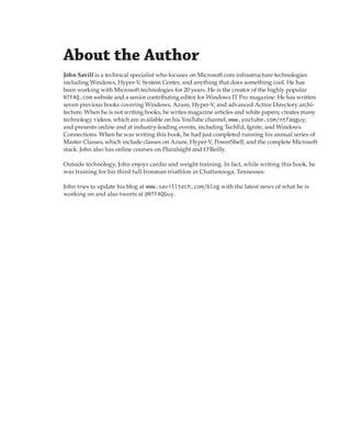
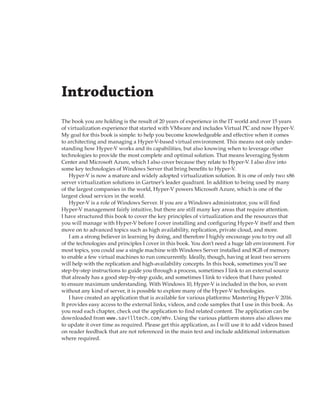
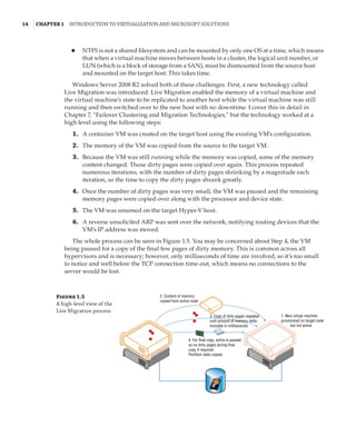
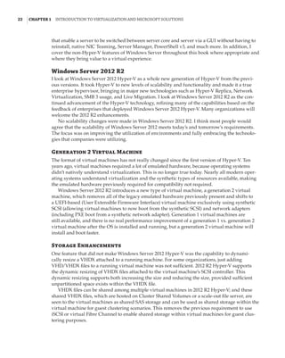
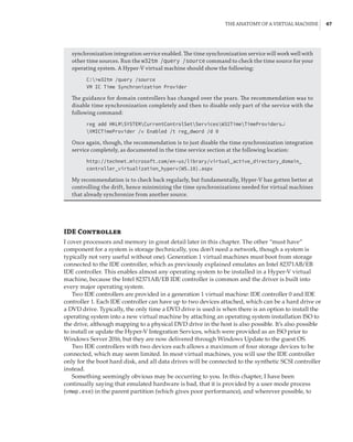
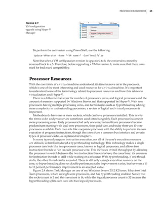
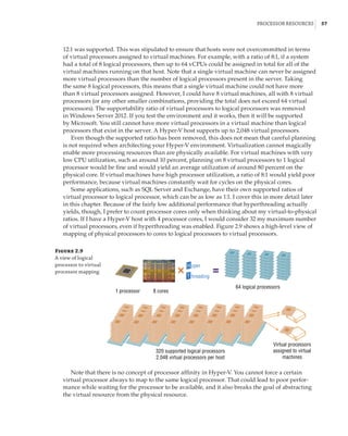
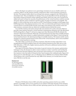
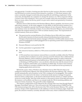
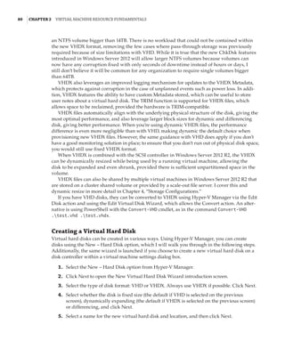
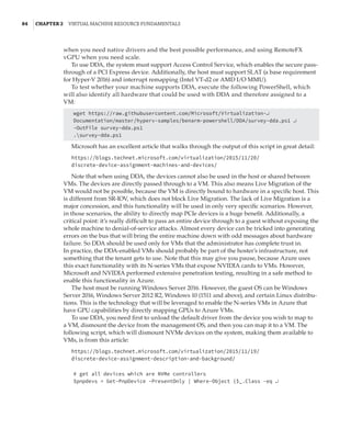
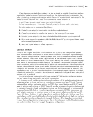
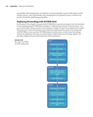
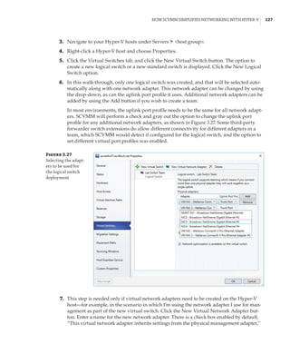
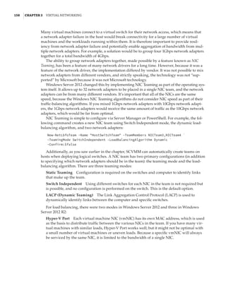
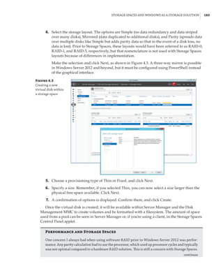
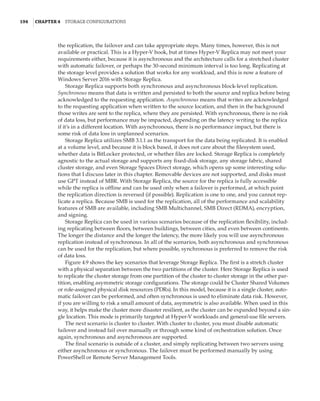
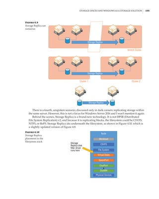
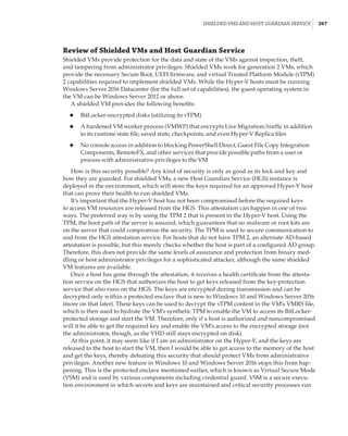
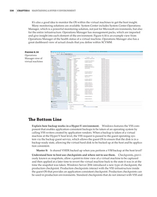
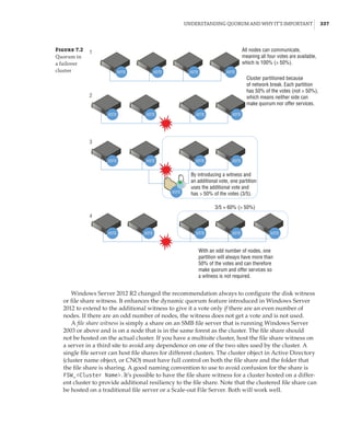
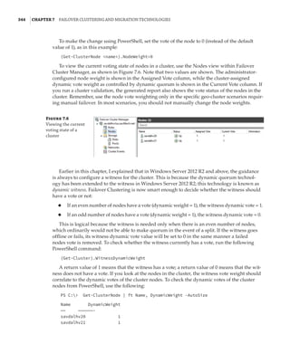
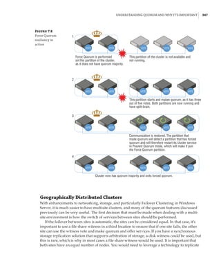
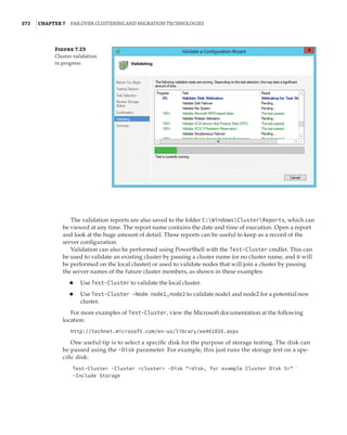
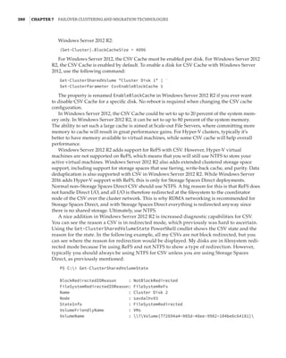
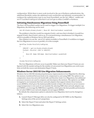
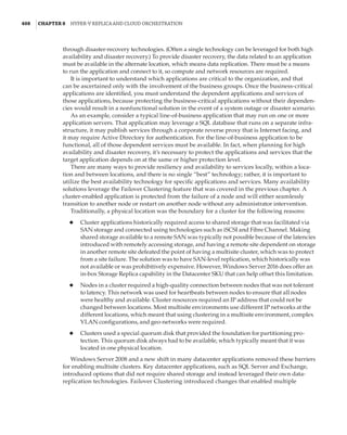
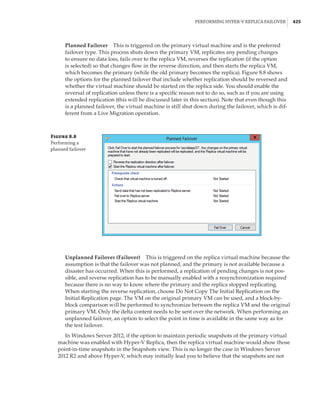
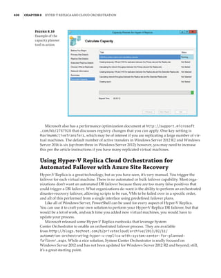
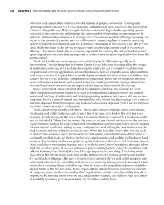
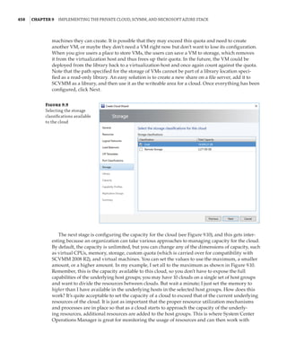
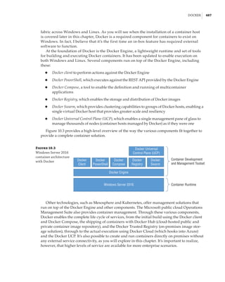
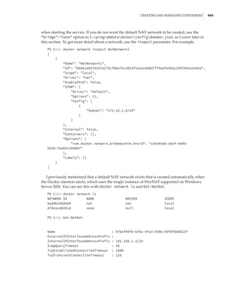
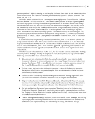
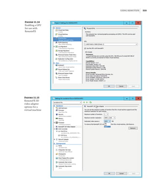
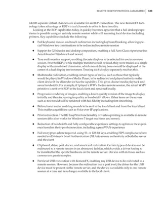
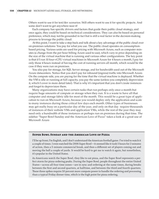
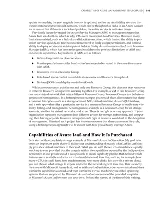
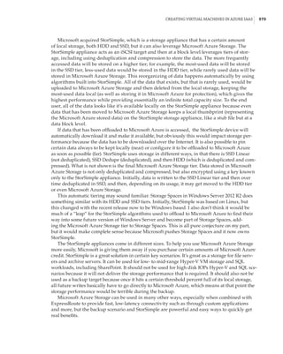
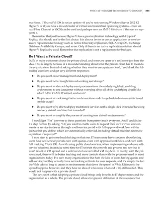
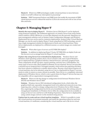
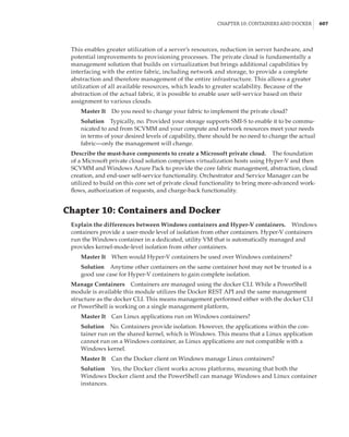
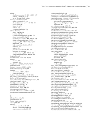
new site-awareness available in the Windows Server 2016 cluster. This is shown in Figure 4.12:
The cluster is divided into two sites, and in each site a site-scoped pool is created via Storage
Spaces Direct; a virtual disk is created, and that virtual disk is then replicated using Storage
Replica to a virtual disk created on a storage pool on the other side.
Figure 4.12
Storage Replica
working with Storage
Spaces Direct
Stretch Cluster
Storage Replica
SMB 3
SAS SAS
Virtual Disk 1
Storage Pool 1 Storage Pool 2
SAS SAS
Virtual Disk 2
SMB 3
Server Message Block Usage
While Server Message Block (SMB) has been available in Windows for a long time, its usage has
been limited to basic file-sharing scenarios, such as users accessing their home drives or a file
share containing archived data. Hyper-V had long had the requirement of having block-level
access to its storage; that is, the host mounted the volumes that contained the virtual machines,
which could be direct-attached or connected via mediums such as iSCSI or Fibre Channel.
However, this was a challenge for many organizations that were used to using file-level proto-
cols with virtualization. Specifically, VMware supported NFS for virtual machine storage, which
was available in many NAS solutions that typically are much cheaper than SAN solutions and
are a good fit for many environments.
Windows Server 2012 invested greatly in SMB to make it an enterprise-ready solution suit-
able for storing virtual machines and other enterprise workloads, such as SQL Server databases.
SMB 3 introduced many new features and performance improvements to make it a realistic
choice for virtualization storage.](https://image.slidesharecdn.com/masteringwindowshyper-v-2016-220718185053-392ce9da/85/Mastering-Windows-Hyper-V-2016-pdf-221-320.jpg)

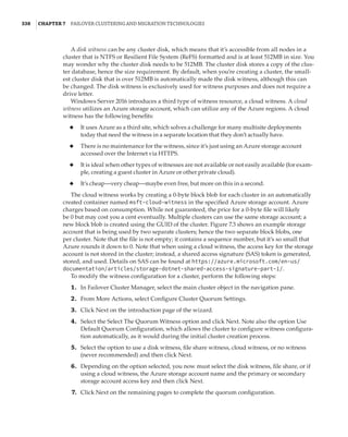
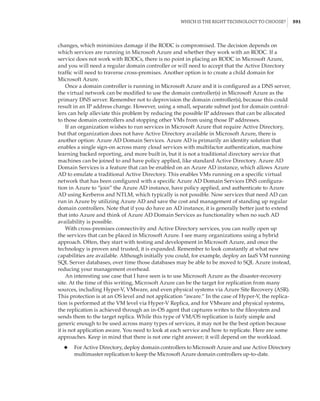
![Hyper-V Integration Services and Supported Operating Systems | 289
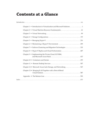
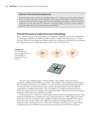
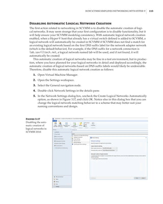
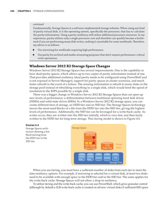
Figure 5.32
Registry within a
virtual machine
showing informa-
tion about the host
Conversely, the Hyper-V host reads information from HKEY_LOCAL_MACHINESOFTWARE
MicrosoftVirtual MachineAuto in the guest, which is populated by the guest OS, giving
Hyper-V a lot of information about the OS, including version, naming, and IP configuration.
This type of information exchange can be useful for many types of management operations,
automation, and inventory. The complete list of values can be found at the following location,
which documents the Msvm_KvpExchangeDataItem class:
http://msdn.microsoft.com/en-us/library/cc136850(v=vs.85).aspx
You can create your own custom values within the VM that can be read by the Hyper-V host
by adding string values under HKEY_LOCAL_MACHINESOFTWAREMicrosoftVirtual Machine
Guest. This would be useful to, for example, populate the type of server in the guest using
a custom process, such as SQLServer or IISServer, which could then be read from the host to
ascertain the type of server running in the VM. There is no PowerShell cmdlet available to read
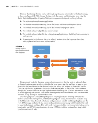
values set in the guest from the Hyper-V host. Instead, you use WMI. The following PowerShell
script reads the fully qualified domain name from within the guest OS from the Hyper-V host
for VM savdaldc02:
$vmName = savdaldc02
$vm = Get-WmiObject -Namespace rootvirtualizationv2 `
-Class Msvm_ComputerSystem `
-Filter ElementName='$vmName'
$vm.GetRelated(Msvm_KvpExchangeComponent).GuestIntrinsicExchangeItems | % {
$GuestExchangeItemXml = ([XML]$_).SelectSingleNode(`
/INSTANCE/PROPERTY[@NAME='Name']/VALUE[child::text()='FullyQualifiedDomainName'])
if ($GuestExchangeItemXml -ne $null)
{
$GuestExchangeItemXml.SelectSingleNode( `
/INSTANCE/PROPERTY[@NAME='Data']/VALUE/child::text()).Value
}
}
Heartbeat Allows Hyper-V to check the responsiveness of the guest operating system by a
heartbeat check.
Backup (Volume Snapshot) A powerful feature that I cover in Chapter 6, “Maintaining
a Hyper-V Environment;
” this allows backup requests at the host level to be passed to the](https://image.slidesharecdn.com/masteringwindowshyper-v-2016-220718185053-392ce9da/85/Mastering-Windows-Hyper-V-2016-pdf-313-320.jpg)
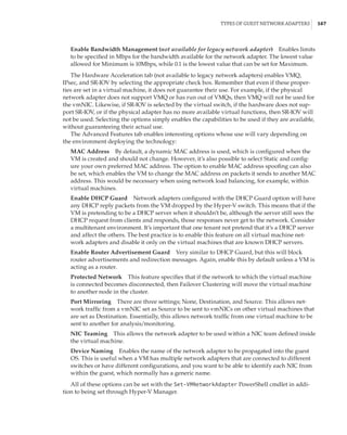
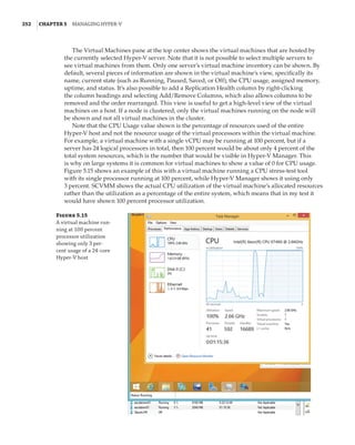
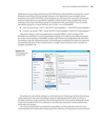
![Performance Tuning and Monitoring with Hyper-V | 327
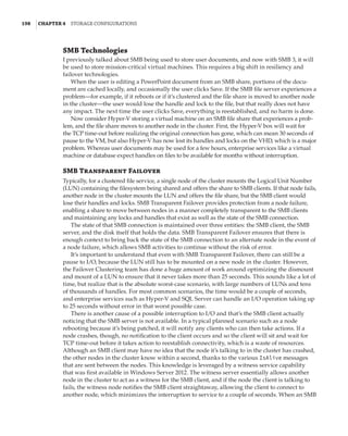
metrics are available, as covered in Chapter 4. Here is an example of the basic metering output
for networking and storage:
PS C: $report = Measure-VM -VMName savdalfs01
PS C: $report.NetworkMeteredTrafficReport
LocalAddress RemoteAddress Direction TotalTraffic(M)
————————————-————-———————-
0.0.0.0/0 Inbound 2121
0.0.0.0/0 Outbound 3479
::/0 Inbound 88
::/0 Outbound 2
PS C: $report.HardDiskMetrics
VirtualHardDisk : HardDiskDrive (Name = 'Hard Drive on SCSI
controller number 0 at location 0', VMName =
'VM1') [Id = 'Microsoft:6C79B7C6–13CB-4E22-B528–
870F92A8D3737E4A44C7-C488–4E8F-9588–8D3699
252C9B00D', VMId = '6c79b7c6–13cb-4e22-b528–
870f92a8d373']
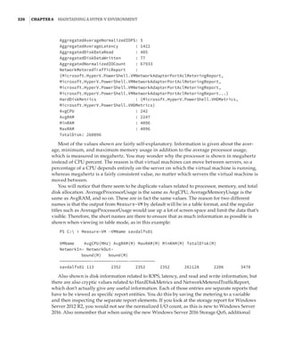
AverageNormalizedIOPS: 41
AverageLatency : 1915
DataRead : 409
DataWritten : 79
NormalizedIOCount : 68626
VirtualHardDisk : HardDiskDrive (Name = 'Hard Drive on SCSI
controller number 0 at location 1', VMName =
'VM1') [Id = 'Microsoft:6C79B7C6–13CB-4E22-B528–
870F92A8D3737E4A44C7-C488–4E8F-9588–8D3699
252C9B01D', VMId = '6c79b7c6–13cb-4e22-b528–
870f92a8d373']
AverageNormalizedIOPS: 0
AverageLatency : 0
DataRead : 1
DataWritten : 0
NormalizedIOCount: 18
The resource-metering functionality gives a great view into the metrics of a single virtual
machine. However, if there are 10 virtual machines in a certain group—for example, all of the
virtual machines for a certain client or all of the SQL servers—then to get the total resource for
all of the groups’ virtual machines, you would have to add all the metrics together manually or
write something. This is where the concept of resource pools can be useful. CPUs, memory, stor-
age (VHD, ISO, Fibre Channel, and virtual floppy disk), and network adapters can be added to a
resource pool from a number of virtual machines. Once the resources are added to the resource](https://image.slidesharecdn.com/masteringwindowshyper-v-2016-220718185053-392ce9da/85/Mastering-Windows-Hyper-V-2016-pdf-351-320.jpg)


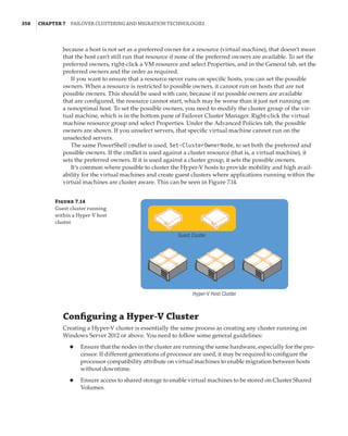
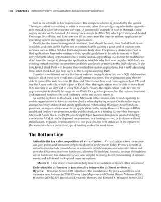
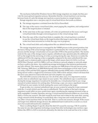
![362 |Chapter 7 Failover Clustering and Migration Technologies
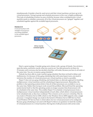
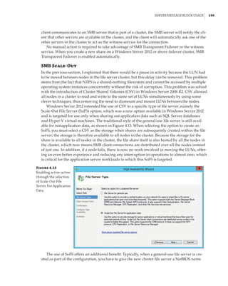
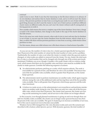
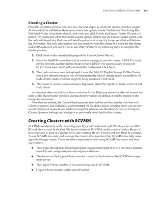
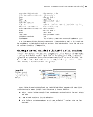
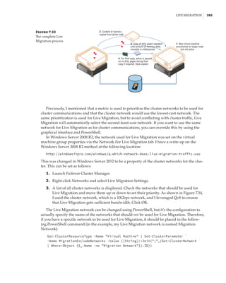
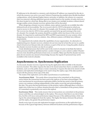
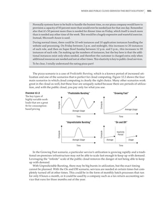
Figure 7.18
Cluster network
properties
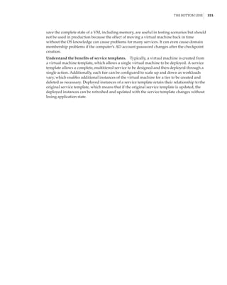
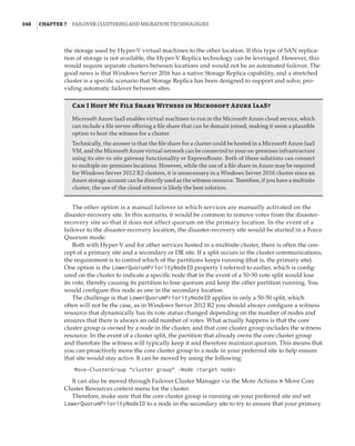
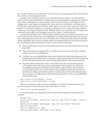
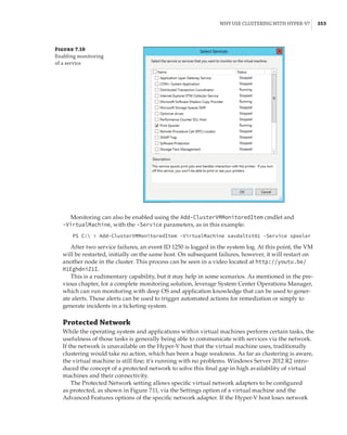
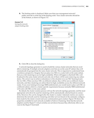
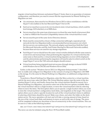
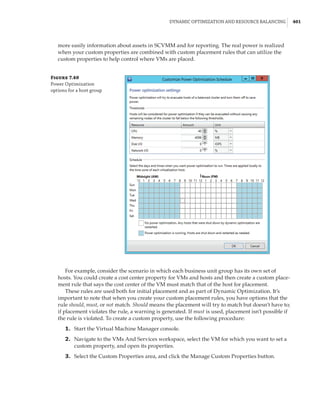
Notice that for each network, the following options are available, which are initially config-
ured during clustering setup based on the IP configuration of the network adapter and whether
a gateway was configured. These configure the role of the networks in relation to cluster activi-
ties, and they also have a numeric value, shown in square brackets:
Allow Cluster Network Communication On This Network [1] This is set automatically
for any IP-enabled network adapter, and it allows the cluster to use this network if neces-
sary unless the iSCSI Software Initiator is bound to the IP address, in which case this is not
configured.
Allow Clients To Connect Through This Network [3] This is set automatically if the IP
configuration for the network adapter has a gateway defined, which suggests external com-
munication and therefore client communication.
Do Not Allow Cluster Network Communication On This Network [0] The cluster cannot
use this network. This would be configured on something like an iSCSI network, which is
automatically set if the iSCSI Software Initiator is bound to the IP address.
These roles can also be configured by using this PowerShell command:
(Get-ClusterNetwork network name).Role=new role number
These three settings are used by clustering to create an automatic metric for each network
adapter, which sets the priority for the preferred network to be used for cluster communications
from all those available. You can see the metrics by using the following PowerShell:
PS C: Get-ClusterNetwork | ft Name, Role, AutoMetric, Metric -AutoSize
Name Role AutoMetric Metric
—— ——————————](https://image.slidesharecdn.com/masteringwindowshyper-v-2016-220718185053-392ce9da/85/Mastering-Windows-Hyper-V-2016-pdf-386-320.jpg)


This document provides an overview of the history and evolution of Hyper-V and virtualization technologies within Microsoft solutions. It discusses how virtualization has changed computing and key features introduced in Windows Server releases such as 2008, 2008 R2, 2012, 2012 R2, and 2016. It also covers Hyper-V licensing and the role that System Center products play in managing Hyper-V environments.