Downloaded 15 times

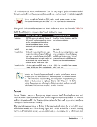
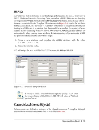
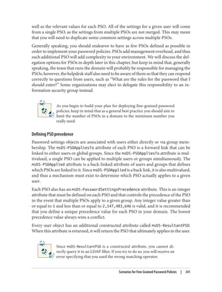
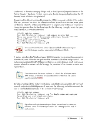
![Active Directory
by Brian Desmond, Joe Richards, Robbie Allen, and Alistair G. Lowe-Norris
Copyright © 2013 Brian Desmond, Joe Richards, Robbie Allen, Alistair Lowe-Norris. All rights reserved.
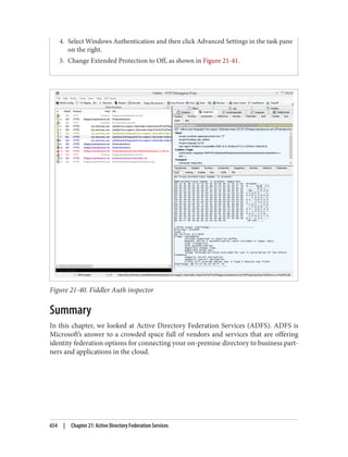
Printed in the United States of America.
Published by O’Reilly Media, Inc., 1005 Gravenstein Highway North, Sebastopol, CA 95472.
O’Reilly books may be purchased for educational, business, or sales promotional use. Online editions are
alsoavailableformosttitles(http://my.safaribooksonline.com).Formoreinformation,contactourcorporate/
institutional sales department: 800-998-9938 or corporate@oreilly.com.
Editor: Rachel Roumeliotis
Production Editor: Rachel Steely
Copyeditor: Jasmine Kwityn
Proofreader: Rachel Head
Indexer: Bob Pfahler
Cover Designer: Karen Montgomery
Interior Designer: David Futato
Illustrators: Robert Romano and Rebecca Demarest
April 2013: Fifth Edition
Revision History for the Fifth Edition:
2013-04-10: First release
See http://oreilly.com/catalog/errata.csp?isbn=9781449320027 for release details.
Nutshell Handbook, the Nutshell Handbook logo, and the O’Reilly logo are registered trademarks of O’Reilly
Media, Inc. Active Directory, the image of domestic cats, and related trade dress are trademarks of O’Reilly
Media, Inc.
Many of the designations used by manufacturers and sellers to distinguish their products are claimed as
trademarks. Where those designations appear in this book, and O’Reilly Media, Inc., was aware of a trade‐
mark claim, the designations have been printed in caps or initial caps.
While every precaution has been taken in the preparation of this book, the publisher and authors assume
no responsibility for errors or omissions, or for damages resulting from the use of the information contained
herein.
ISBN: 978-1-449-32002-7
[LSI]](https://image.slidesharecdn.com/ad-designdeploying-220718185045-afb05777/85/AD-Design-Deploying-pdf-4-320.jpg)


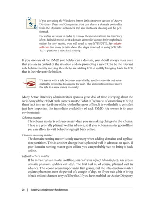
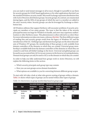

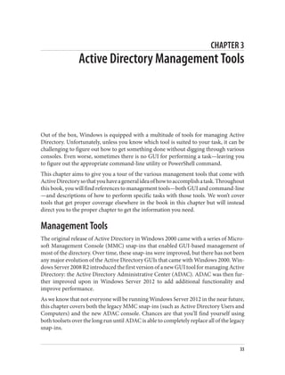
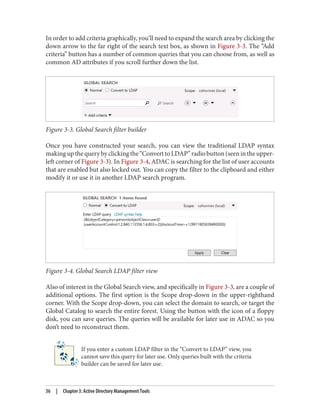
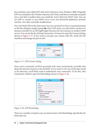
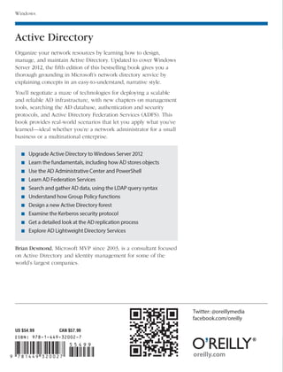
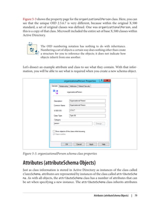
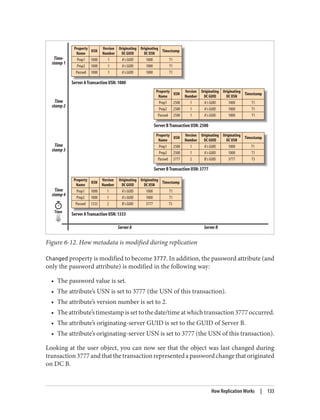
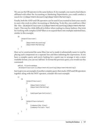
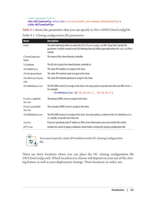
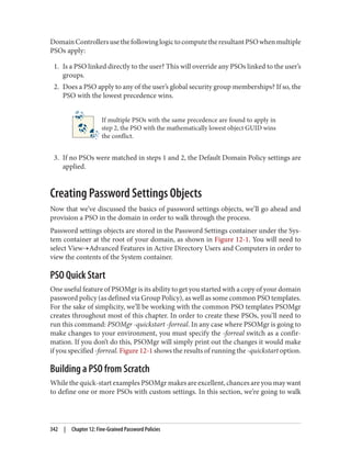
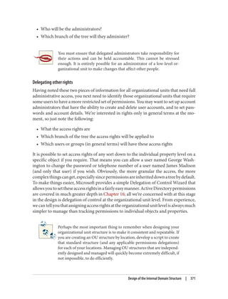
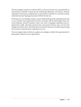
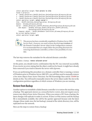
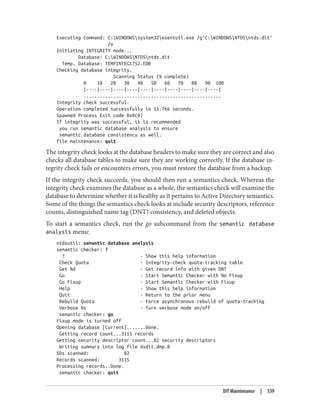
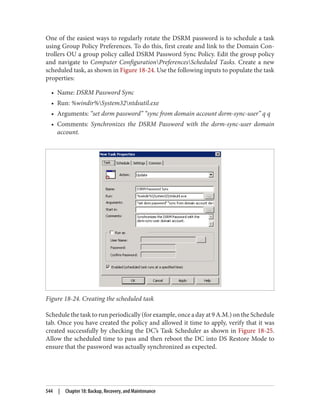
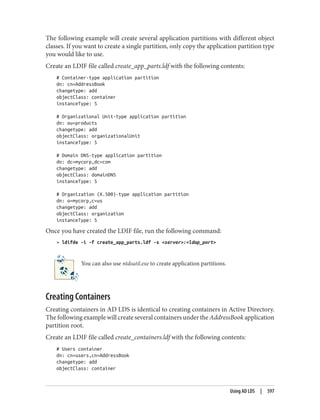
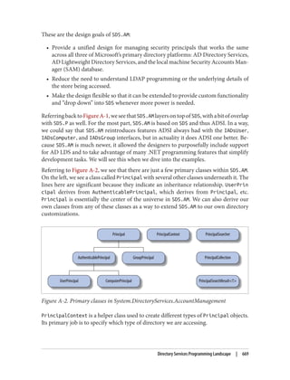
![***Call Modify...
ldap_modify_s(ld, 'CN=Brian Desmond,OU=People,DC=cohovines,DC=com',[1] attrs);
Modified "CN=Brian Desmond,OU=People,DC=cohovines,DC=com".
-----------
If the modification fails, LDP will provide an error code and you can resubmit your
request.
There are a number of other useful features in the LDP tool, including the ability to
delete an object or tree (Browse→Delete), rename an object (Browse→Modify DN),
create objects (Browse→Add Child), view replication metadata (Browse→Replica‐
tion→Replication Metadata Descriptor, or right-click the object and click Ad‐
vanced→Replication Metadata), and view the ACL (security descriptor) of an object
(Browse→Security→Security Descriptor, or right-click the object and click Ad‐
vanced→Security Descriptor). We’ll cover the security descriptor functionality in LDP
in more depth in Chapter 21.
LDP is a powerful tool that you can use to perform nearly any task in an LDAP directory.
Taking advantage of LDP’s power requires a sometimes deep understanding of the
LDAP protocol, but when you need to look at raw data or perform an operation directly
on the directory without any abstraction, LDP is an excellent tool to have in your tool
belt.
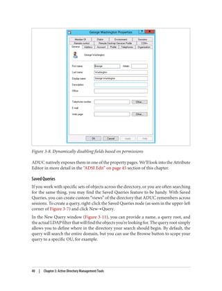
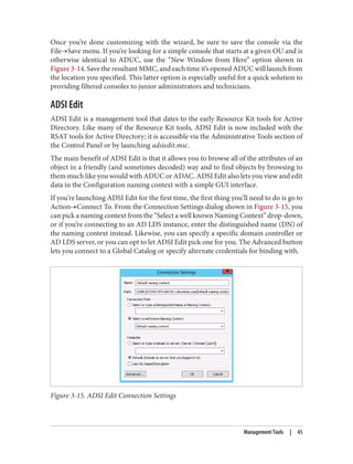
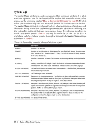
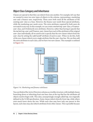
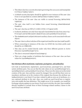
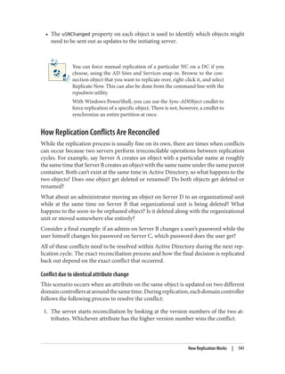
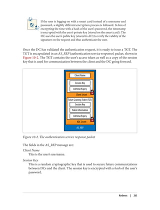
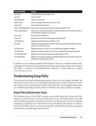
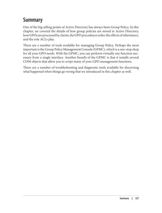
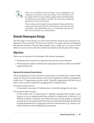
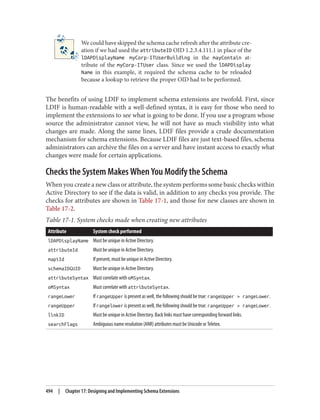
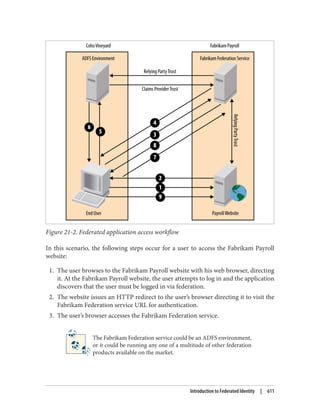
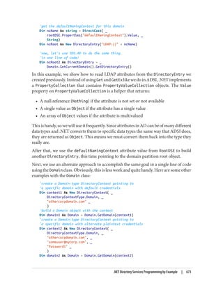
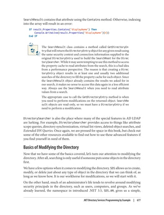
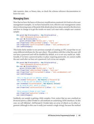
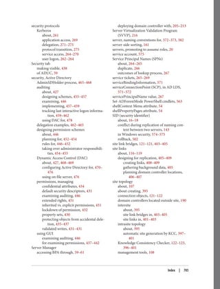
Customizing the Active Directory Administrative Snap-ins
Unfortunately, the Active Directory Administrative Center is not customizable in terms
of the data that’s available in the console. The legacy snap-ins such as Active Directory
Users and Computers are highly extensible, however. One of the most common exam‐
ples of extending ADUC is to display additional attributes, perhaps even ones you’ve
created. Let’s say that you decide to add an attribute called myCorp-LanguagesSpoken
to the Active Directory schema. In turn, you want myCorp-LanguagesSpoken to be dis‐
played in ADUC so others can view the languages a user speaks. Fortunately, the legacy
Active Directory snap-ins (e.g., ADUC and AD Sites and Services) are customizable by
modifying one or more attributes in Active Directory. You can also extend the func‐
tionality of a snap-in using Windows Scripting Host (WSH), Visual Basic (VB), or any
other COM-based language.
This section is devoted to reviewing the components behind the Active Directory ad‐
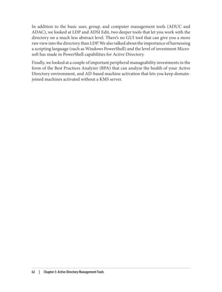
ministrative snap-ins and how you can modify them to meet your needs. These com‐
ponents include:
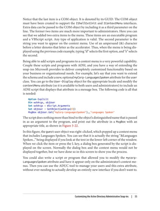
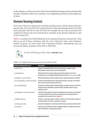
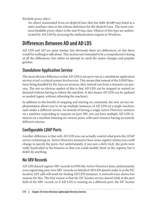
Display specifiers
Objects in Active Directory that contain localized user interface information
Property pages
Tabbed dialog boxes that display information
52 | Chapter 3: Active Directory Management Tools](https://image.slidesharecdn.com/ad-designdeploying-220718185045-afb05777/85/AD-Design-Deploying-pdf-78-320.jpg)


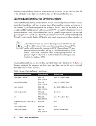
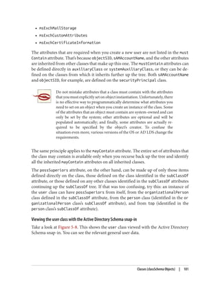

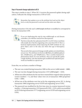

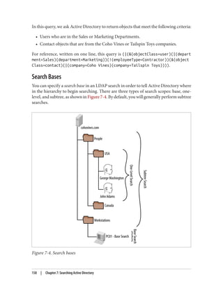
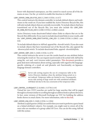
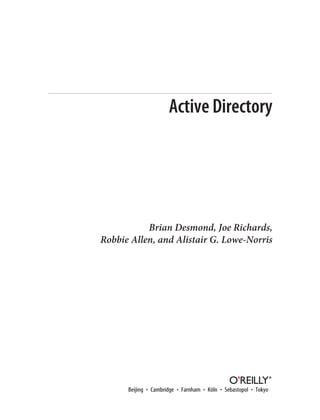
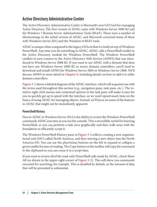
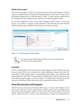
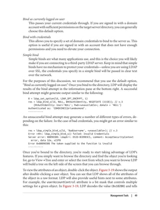
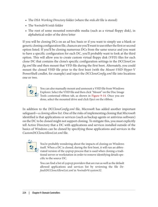
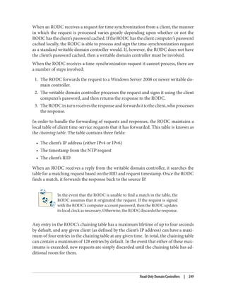
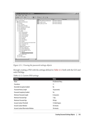
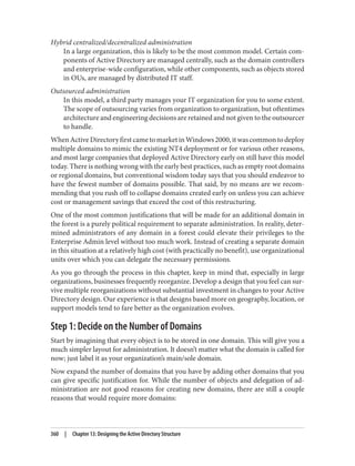
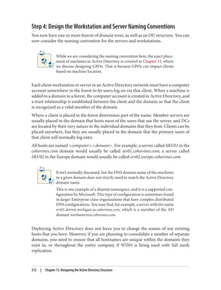
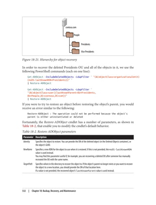
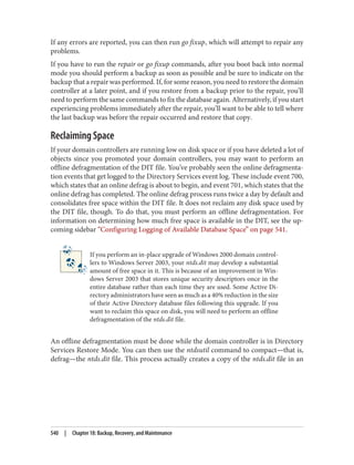
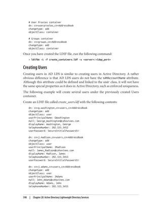
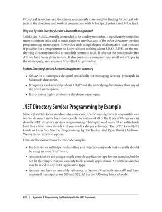
![adfind -asq member -b "cn=All Users,ou=Groups,dc=cohovines,dc=com"
-f "objectClass=user"
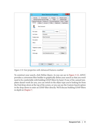
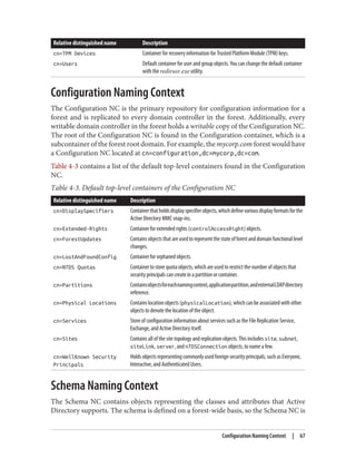
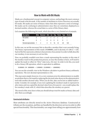
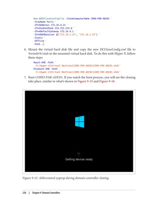
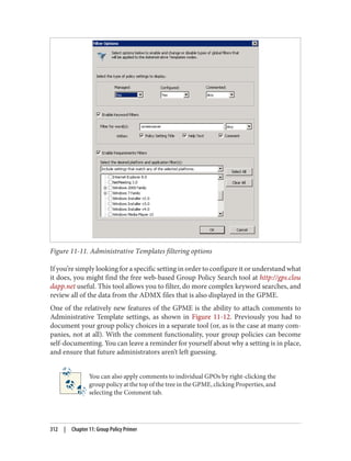
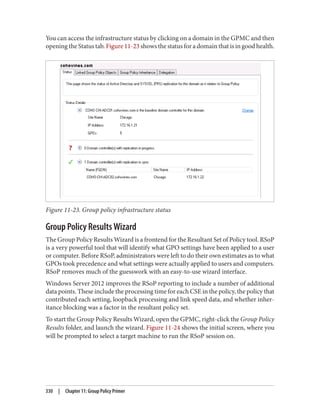
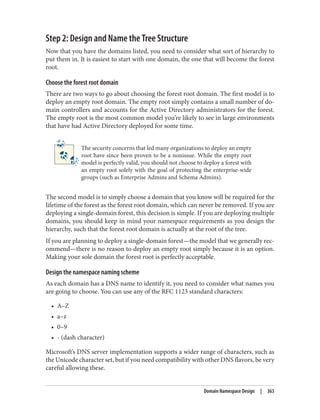
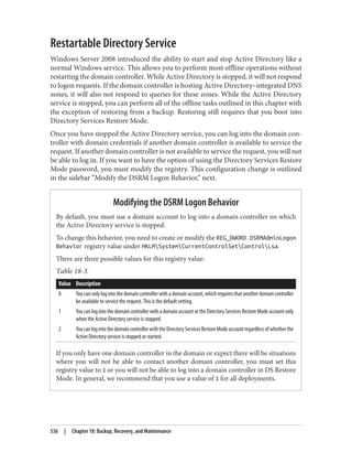
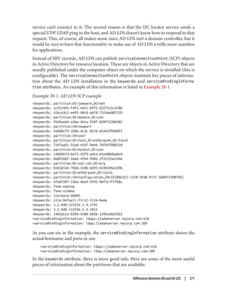
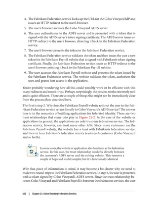
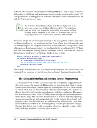
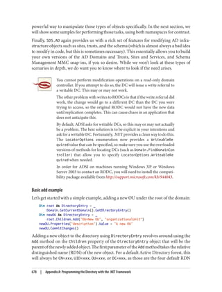
In the case of LDAP controls that we didn’t demonstrate with AdFind in the preceding
list, you can use LDP to exercise many controls. In most cases, go to Browse→Search
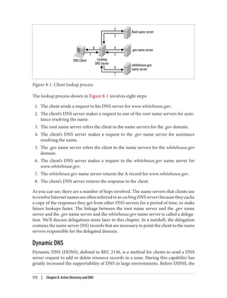
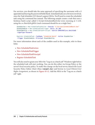
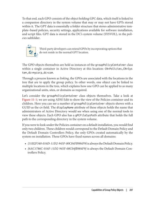
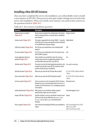
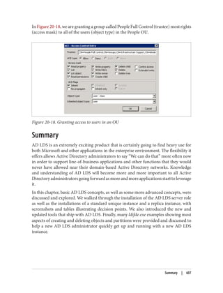
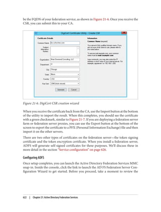
and then click Options. On the Options screen, click Controls, as shown in Figure 7-5.
Use the “check in” button to add a control to the request once you configure it on the
lefthand side of the screen. Virtual list view (VLV) searches can be conducted by using
the dedicated VLV option available under Browse→Virtual List View.
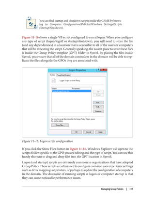
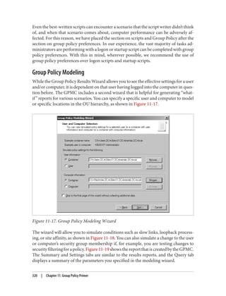
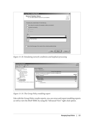
Figure 7-5. LDP Controls dialog
Attribute Data Types
Certain types of attributes are more challenging to work with than what we have looked
at so far. These types of attributes include dates and times (such as the pwdLastSet
attribute) and bit masks (such as the userAccountControl attribute). Active Directory
supports querying these attributes; it just takes a bit of additional effort.
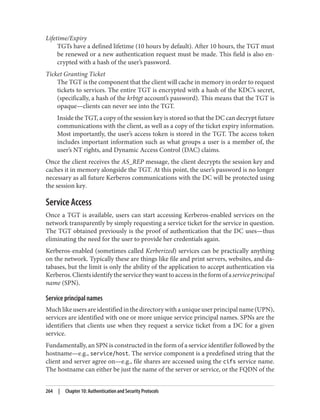
Dates and Times
When you need to find users with expired passwords or objects that were created before
a certain time, you’ll need to work with the formats that Active Directory stores times
in. These formats vary by attribute. The two most common are the 64-bit NT FILE
TIME format and the more standards-based generalized time syntax.
NT FILETIMEs are integers that count the number of 100-nanosecond intervals since
January 1, 1601. Generalized time, on the other hand, simply stores a timestamp in a
more legible format: YYMMDDHHMMSS[.fffZ]. This format is year, month, day, hour,
minute, and second. The optional three-digit decimal value is fractions of a second. The
trailing Z indicates that the time is universal or Zulu time. If the Z is not present, the
time is local time.
162 | Chapter 7: Searching Active Directory](https://image.slidesharecdn.com/ad-designdeploying-220718185045-afb05777/85/AD-Design-Deploying-pdf-188-320.jpg)
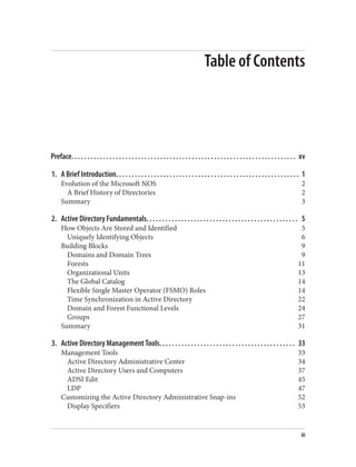
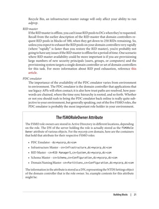
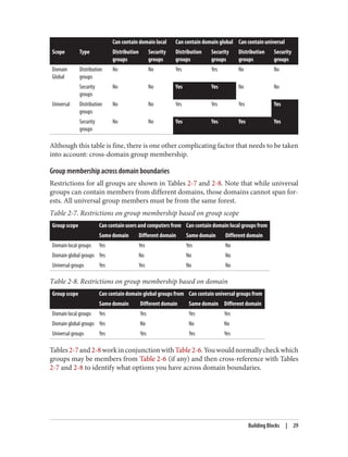
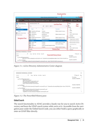
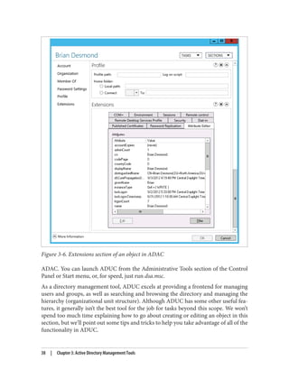
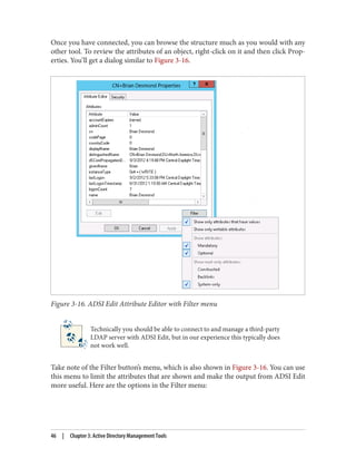
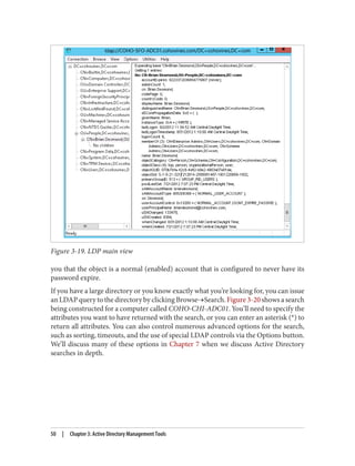
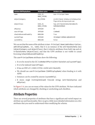
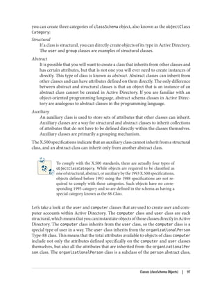
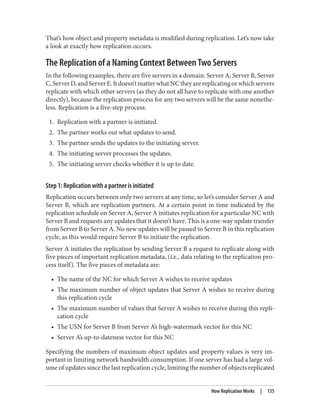
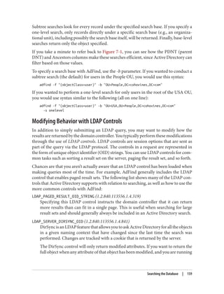
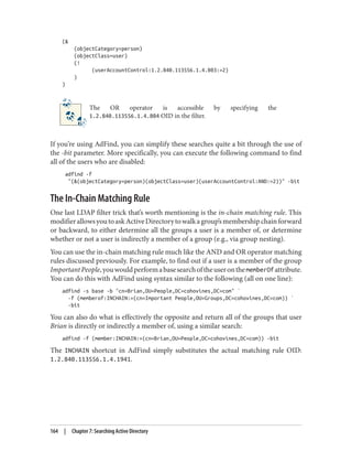
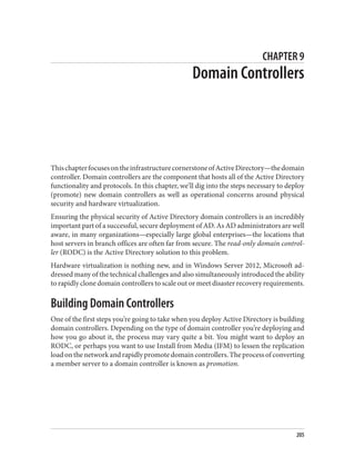
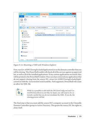
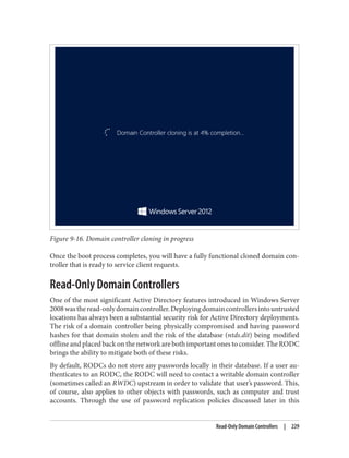
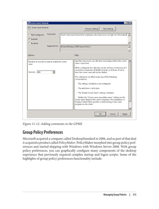
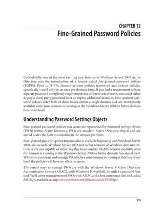
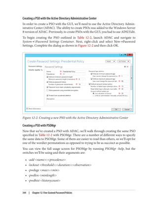
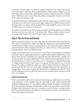
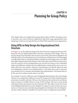
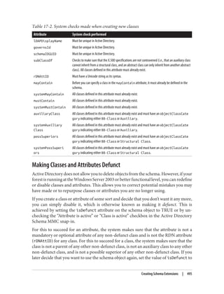
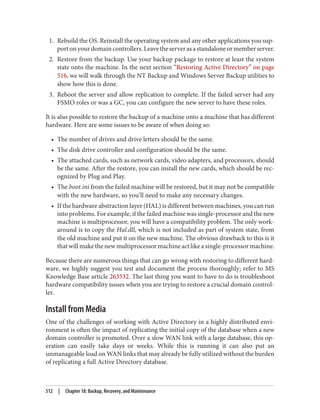
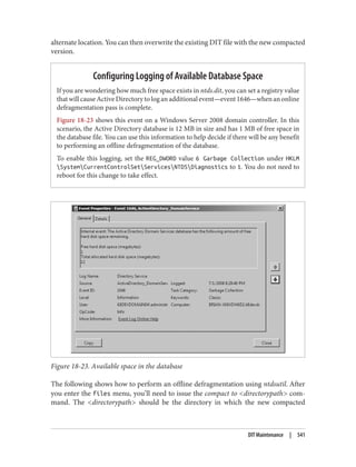
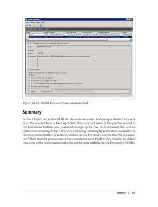
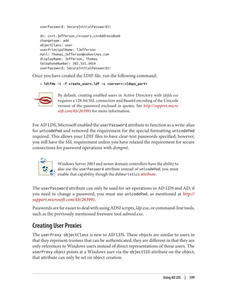
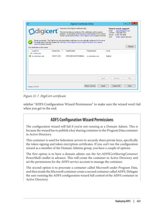
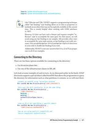
![Encoding values for filters can be accomplished in a couple of ways. In the case of an
attribute such as pwdLastSet, which is stored in FILETIME format, you can ask AdFind
to perform the conversion for you. To retrieve all of the computers whose passwords
were last changed before October 1, 2012, for example, you would use this AdFind
command:
adfind -f "(&(objectClass=computer)(pwdLastSet<={{LOCAL:2012/10/01-12:00:00}}))"
-binenc
If you are using a tool other than AdFind to perform your search, you’ll need to convert
the timestamp in advance. You can use Windows PowerShell to perform the conversion:
[DateTime]::Parse(“10/01/2012”).ToFileTime(). Once you get the result (in this case,
129935412000000000), construct the filter as follows:
(&(objectClass=computer)(pwdLastSet<=129935412000000000))
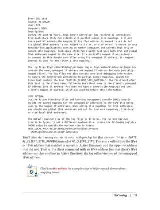
Searches for generalized time attributes such as whenCreated and whenChanged should
be formatted using the syntax described earlier (YYMMDDHHMMSS.fffZ).
When results are returned, they will be in the same format in which Active Directory
expects values to be provided. With AdFind, you can use the -tdcs switch to decode
FILETIME fields (such as pwdLastSet) and the -tdcgts switch to decode generalized time
fields (such as whenChanged and whenCreated).
Much like converting a value to FILETIME format with PowerShell, you can convert a
FILETIME back to readable format by running the following: [DateTime]::FromFile‐
Time(129935412000000000).
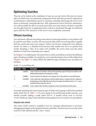
Bit Masks
The most common example of using a bit mask in a search filter will undoubtedly be
to find users that are enabled or disabled. This flag is tracked as the second bit in the
userAccountControl attribute. Active Directory supports two special matching rules
in the LDAP filter to perform AND and OR operations in a filter.
For example, to find users who are disabled, use this filter:
(&
(objectCategory=person)
(objectClass=user)
(userAccountControl:1.2.840.113556.1.4.803:=2)
)
The opposite, finding users who are enabled, requires the use of the NOT operator:
Attribute Data Types | 163](https://image.slidesharecdn.com/ad-designdeploying-220718185045-afb05777/85/AD-Design-Deploying-pdf-189-320.jpg)
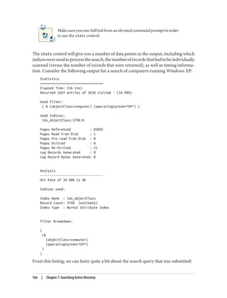
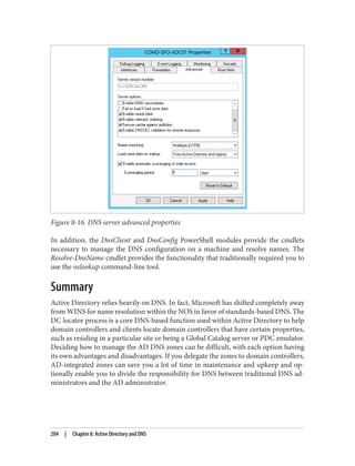
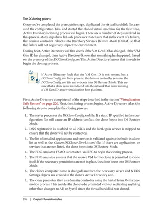
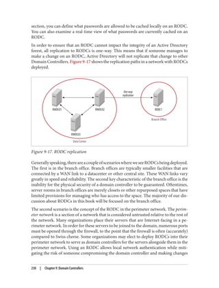
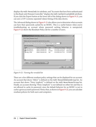
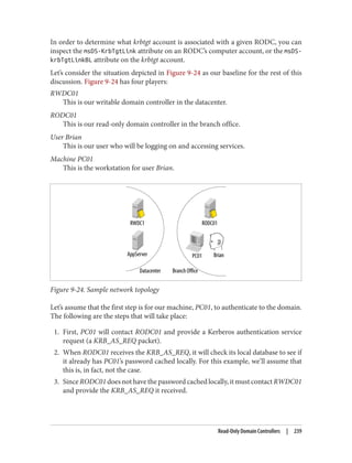
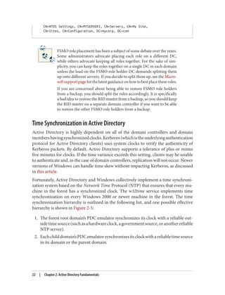
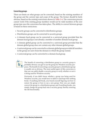
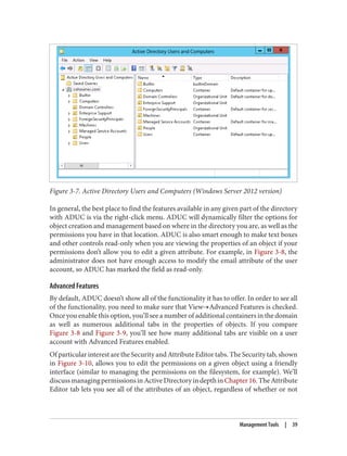
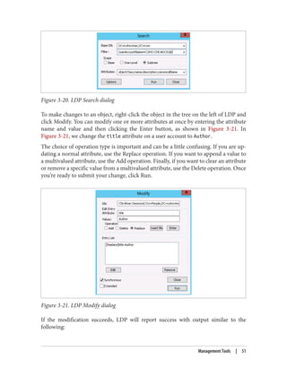
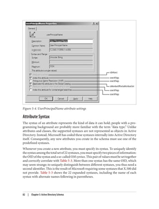
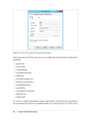
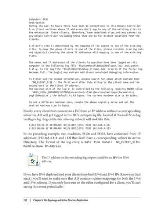
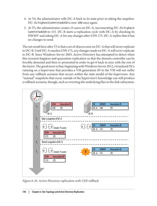
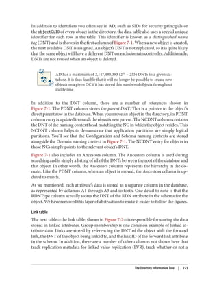
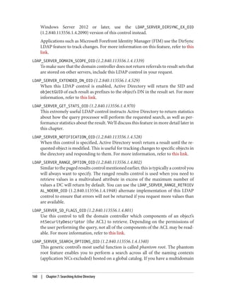
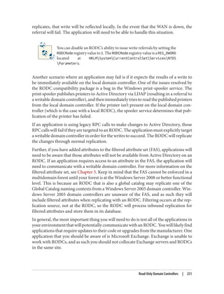
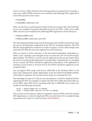
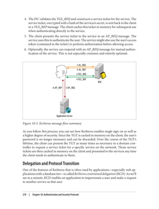
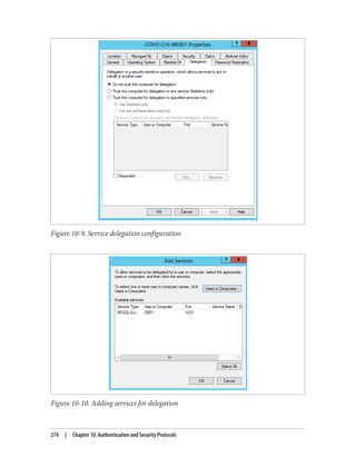
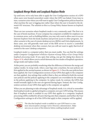
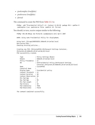
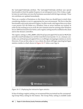
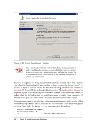
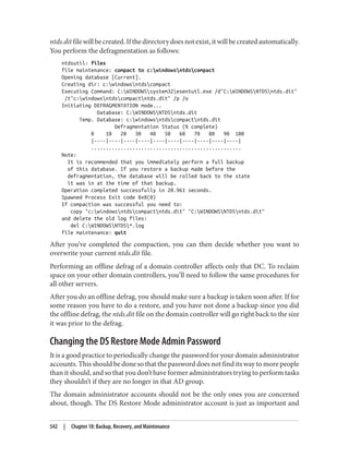
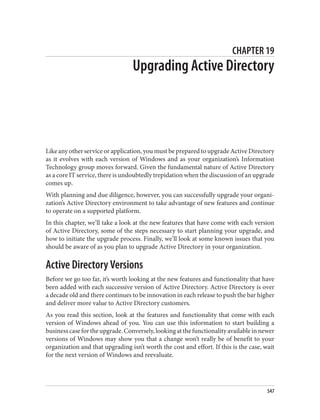
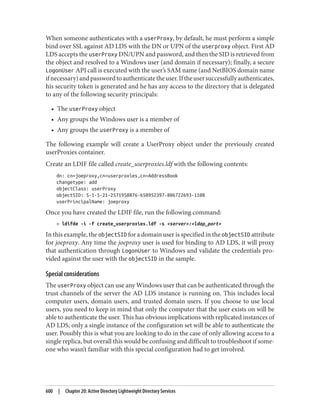
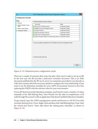
![After completing these steps, user Brian is able to use PC01. During subsequent logons
by user Brian to PC01, the steps taken to obtain a service ticket (TGS) are much simpler:
1. PC01 sends a KRB_TGS_REQ to RODC01 for user Brian to access PC01. The
KRB_TGS_REQ includes Brian’s TGT, which has been encrypted by RODC01.
2. RODC01decryptstheTGTintheKRB_TGS_REQandconstructsaKRB_TGS_REP
that includes a service ticket permitting user Brian to use PC01.
Afterreviewingtheseexamples,youmayhavebeguntonoticetheimportanceofcaching
both the user and computer passwords on the RODC. In order for a user authentication
to succeed, the RODC must possess the passwords for both the user and the computer.
If either of these is not present, the RODC will need to communicate with a writable
domain controller over the WAN. If the WAN is unavailable, the user logon will fail.
The writable domain controller that the RODC contacts must be run‐
ning Windows Server 2008 or newer. If only Windows Server 2003 do‐
main controllers are available, the logon request will fail.
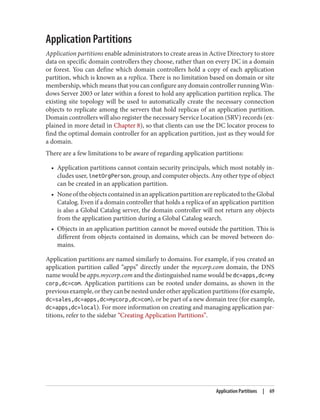
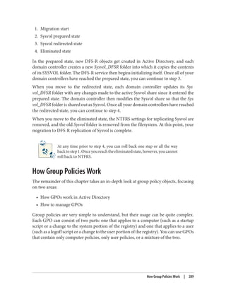
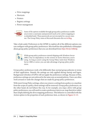
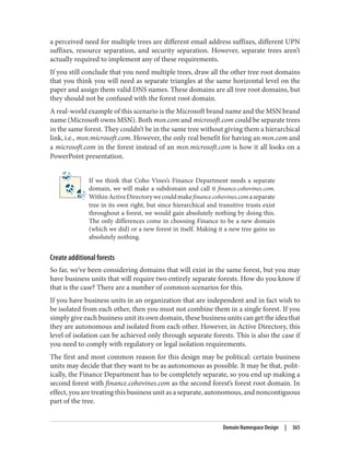
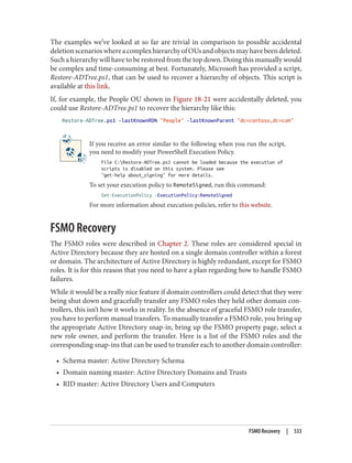
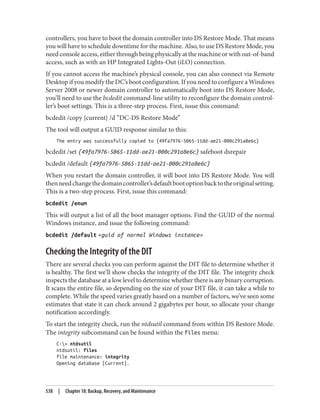
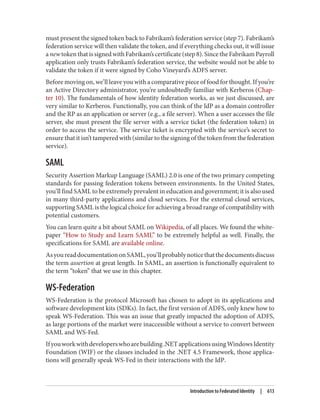
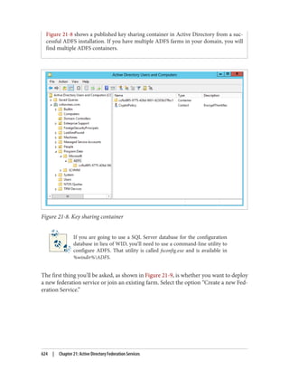
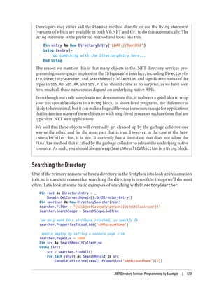
Populating the password cache
Since the success of a logon processed by an RODC can be entirely dependent on
whetherornottheWAN(ormorespecifically,aWindowsServer2008ornewerwritable
domain controller) is available, you may want to prepopulate the RODC’s password
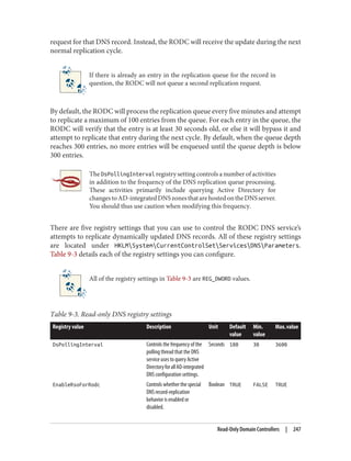
cache.YoucanprepopulatethepasswordcacheusingthePrepopulatePasswordsbutton
shown in Figure 9-21. When you click this button, you will be able to search Active
Directory for users and computers. After selecting the users and computers for which
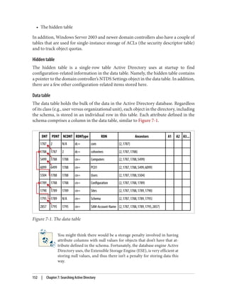
you wish to prepopulate the cache, you will be shown a confirmation dialog similar to
Figure 9-25.
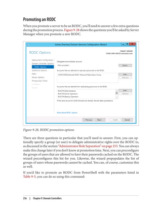
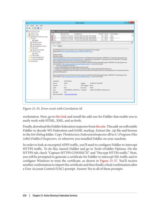
If any errors occur, you will be shown a dialog similar to Figure 9-26 advising you of
those errors. Any principals whose passwords are successfully prepopulated will appear
in the list shown in Figure 9-21.
Managing Cached Passwords with repadmin
The repadmin tool included with Windows Server 2008 and newer includes a number
of switches that you can use to manage an RODC’s password cache. You can use the /
rodcpwdrepl switch to specify one or more users or computers for which the RODC
should immediately request replication of the password. The syntax for this command
(all on one line) is: repadmin /rodcpwdrepl <RODC> <Hub DC> <user/computer dis
tinguished name 1> <[user/computer distinguished name 2]...>
If, for example, you wanted to replicate the password for user bdesmond to an RODC
called K8DEVRODC01 from a RWDC called K8DEVDC01, you would run: repad
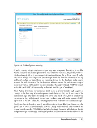
242 | Chapter 9: Domain Controllers](https://image.slidesharecdn.com/ad-designdeploying-220718185045-afb05777/85/AD-Design-Deploying-pdf-268-320.jpg)


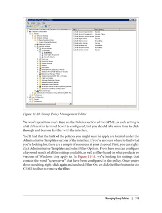
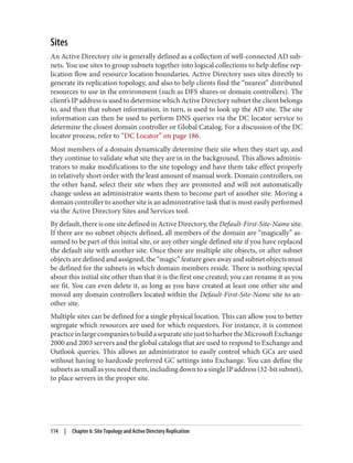
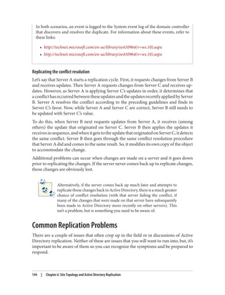
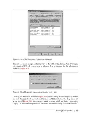
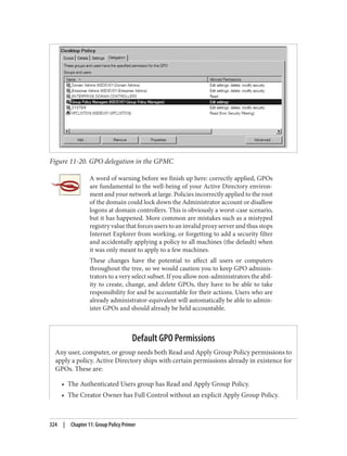
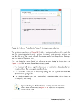
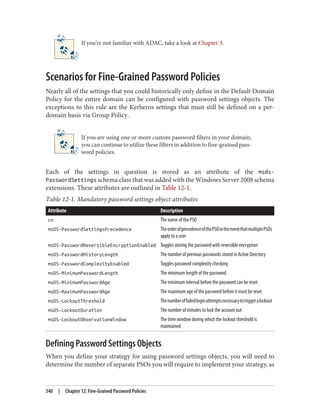
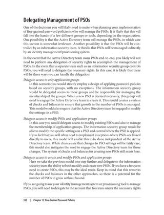
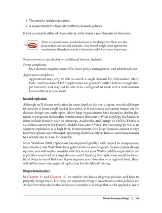
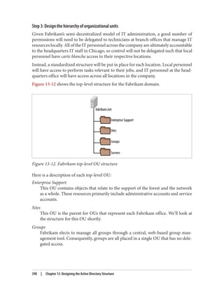
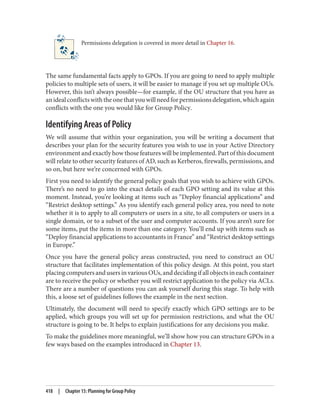
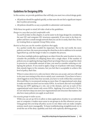
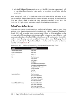
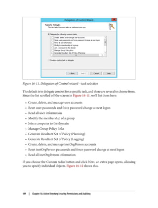
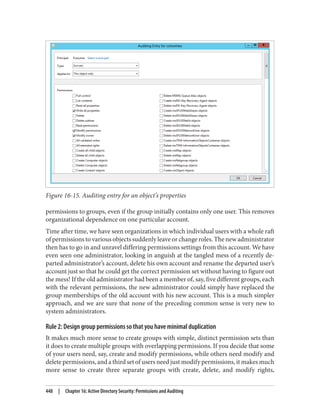
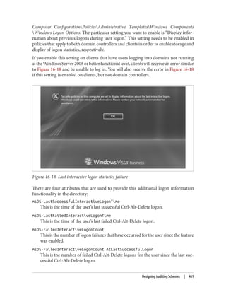
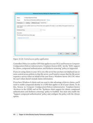
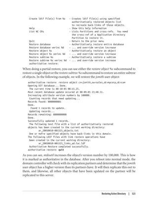
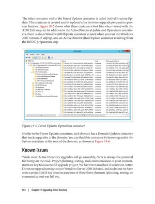
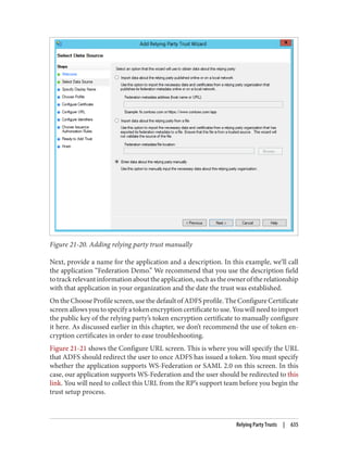
![Delegation and Change Control
When planning your group policy deployment, you have to work out how you will
maintain firm control over GPOs once you start deploying them. Specifically, you need
to consider who will be managing your GPOs and how you will keep control over the
wide-ranging changes they can make.
The importance of change-control procedures
The best way to keep track of GPOs in your organization is through a series of change-
control procedures. These work well whether your GPO administrators are domain
administrators or not. The complexity of the change-control system used for group
policies varies from organization to organization. Some organizations opt to manage
all of their group policies in their configuration management database (CMDB); others
implement simpler systems such as Word documents or Excel spreadsheets. It is im‐
portant that you test any group policy changes in the lab before applying them in pro‐
duction, due to the potential for disrupting service if a faulty policy change is applied.
Microsoft offers a tool called Advanced Group Policy Management (AGPM, part of the
Microsoft Desktop Optimization Pack [MDOP]) to assist with implementing group
policy management permissions and change-control procedures.
Designing the delegation of GPO administration
There are three types of permission that can be considered here:
• The permission to allow sets of users to link policies (and manage the block inher‐
itance setting) to a domain or an organizational unit branch
• The permission to allow sets of users to create GPOs
• The permission to allow sets of users to change the GPOs themselves
Link delegation can be easily accomplished using the Delegation of Control Wizard that
you can access by right-clicking an organizational unit, domain, or site in the Active
Directory MMC and choosing Delegate Control. You’ll want to use the “Manage Group
Policy links” task. Here you are actually delegating read and write access to the gPLink
and gPOptions attributes of objects. If you’re interested in how these attributes work,
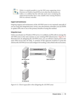
set up a few GPOs in your Active Directory environment and use ADSI Edit to examine
the attributes of the OUs to which you link the GPOs.
We discuss the Delegation Control Wizard in detail in Chapter 16.
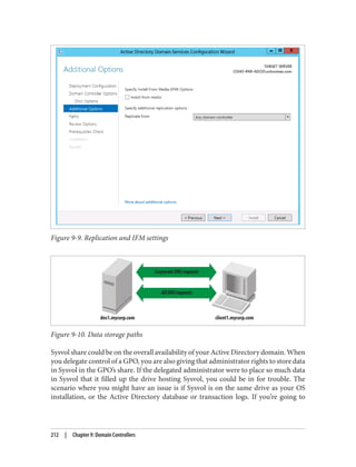
322 | Chapter 11: Group Policy Primer](https://image.slidesharecdn.com/ad-designdeploying-220718185045-afb05777/85/AD-Design-Deploying-pdf-348-320.jpg)
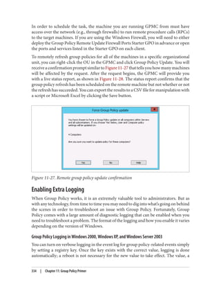


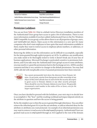
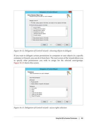
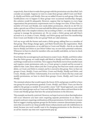
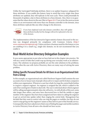
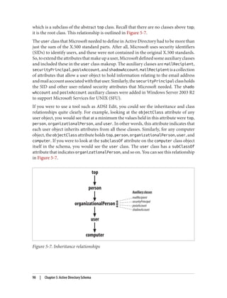
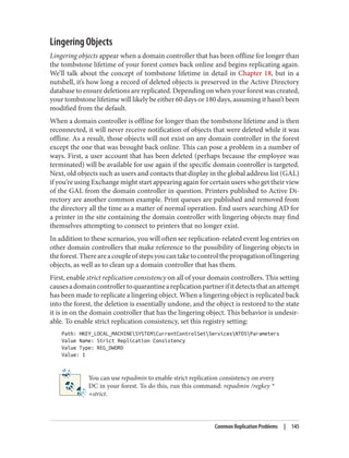
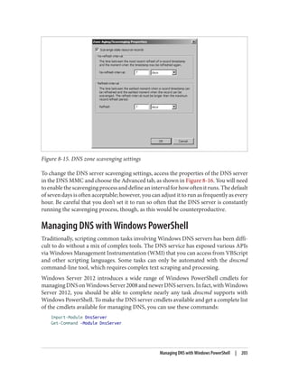
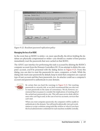
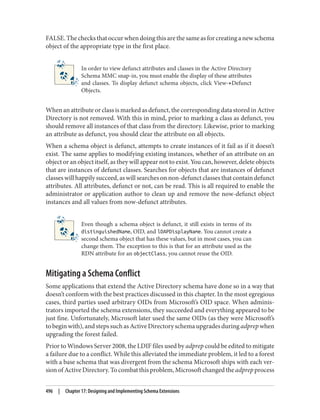
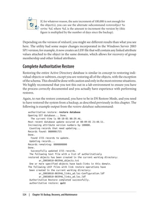
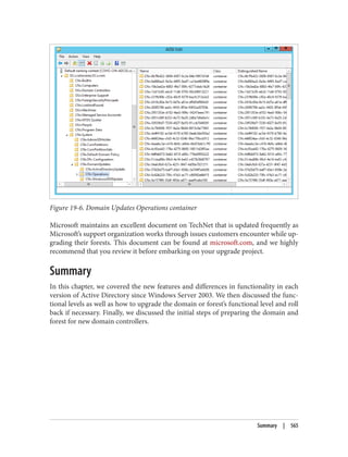
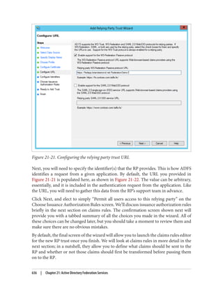
![On the schema master itself, open up the registry using regedt32.exe or regedit.exe and
locate the following key: HKLMSYSTEMCurrentControlSetServicesNTDS
Parameters.
Now, create a new REG_DWORD value called Schema Update Allowed and set the value to
1. That’s all you need to do. You now can edit the schema on that domain controller.
An alternative method for making the change is to copy the following three lines to a
text file with a .reg extension and open it (i.e., run the file) on the DC where you wish
to enable schema updates:
REGEDIT4
[HKEY_LOCAL_MACHINESYSTEMCurrentControlSetServicesNTDSParameters]
"Schema Update Allowed"=dword:00000001
This will automatically modify the registry for you, so you don’t need to do it by hand.
Once you’ve modified the registry on a particular domain controller and placed the user
account that is to make the changes into the Schema Admins group, any changes you
make to the schema on that domain controller will be accepted.
The Schema Cache
Eachdomaincontrollermaintainsacopyoftheentireschemainmemory.Thisisknown
astheschemacache.Itisusedtoprovideaveryrapidresponsewhenrequestingaschema
object OID from a name.
The schema cache is actually a set of hash tables of all the classSchema and attribute
Schema objects known to the system, along with specific indices (attributeID,
mAPIId, and lDAPDisplayName for attributeSchema objects and governsID and lDAP
DisplayName for classSchema objects) for fast searching.
The objects are loaded into the schema cache when the domain controller is booted,
and again five minutes after an update. However, if you need the schema cache to be
updated immediately for some reason, say after the creation of a new object or attribute
class, you can force an immediate reload of the cache.
As we said, the system holds a copy in memory solely to aid in searches that require
quick and regular access to the schema. If the system were to keep the cache and the
actual Active Directory schema in sync, it could be costly in terms of performance;
making changes to the schema is an intensive process due to the significant checking
and setting of object defaults by the system upon creation of new objects. Consequently,
there is a time delay between changes made to the underlying schema and the cached
copy. Typically, the schema tends to be updated in bunches. This is likely to be due to
applications creating multiple classes for their own purposes during an installation or
even normal operation. If classes are still being created after five minutes, the system
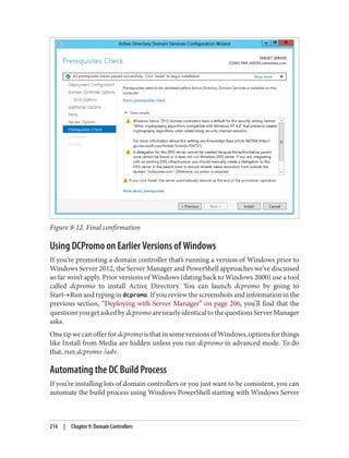
Creating Schema Extensions | 489](https://image.slidesharecdn.com/ad-designdeploying-220718185045-afb05777/85/AD-Design-Deploying-pdf-515-320.jpg)

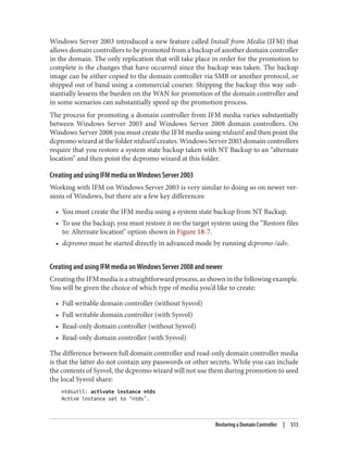
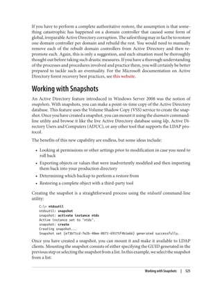
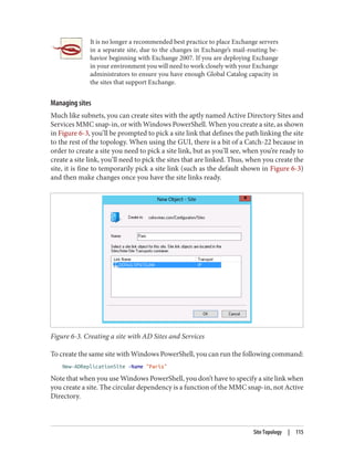
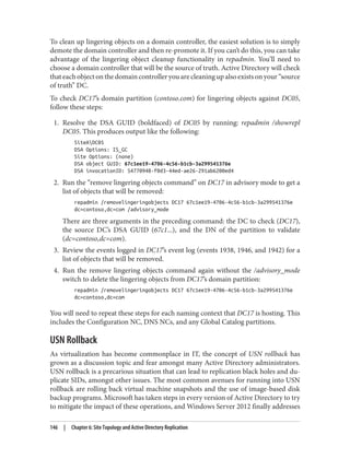
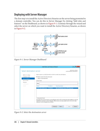
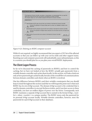
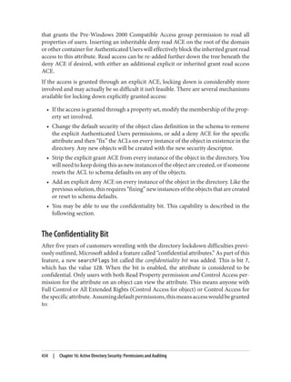
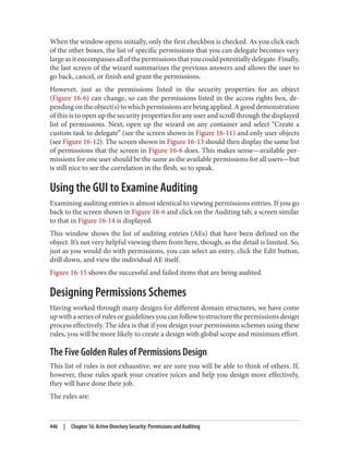
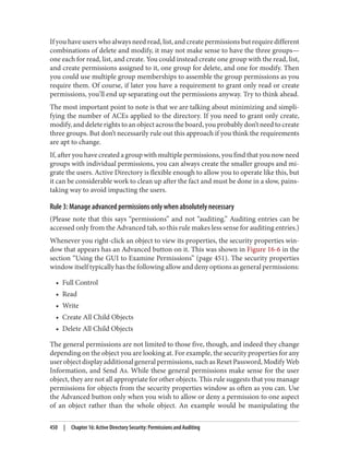
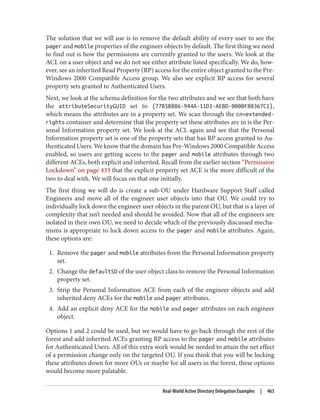
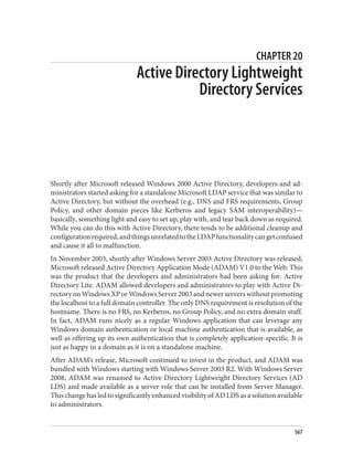
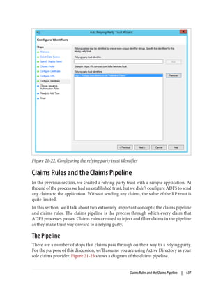
![snapshot: list all
1: 2008/06/30:22:44 {e73b71cd-7e2b-40ee-8871-69575f4b1e66}
2: C: {c8bc59c0-f20b-4bac-a12a-ab6eab737f0c}
snapshot: mount 1
Snapshot {c8bc59c0-f20b-4bac-a12a-ab6eab737f0c} mounted as
C:$SNAP_200806302244_VOLUMEC$
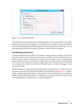
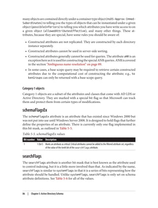
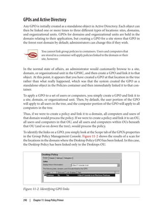
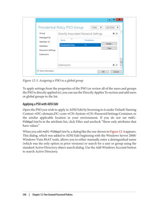
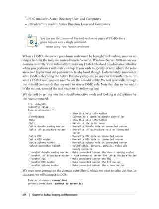
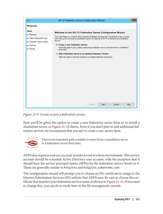
Once the snapshot has been mounted in the filesystem, you can use the dsamain utility
to mount the snapshot version of the Active Directory database and make it accessible
via LDAP. dsamain requires that you provide the path to the database to mount as well
as a port number to listen on. If you only specify the LDAP port, dsamain will auto‐
matically use the subsequent three ports for LDAP over SSL (LDAPS), Global Catalog,
and Global Catalog SSL connections. Thus, if you specify port 10389 for LDAP, ports
10390, 10391, and 10392 will also be used. The command to mount the database in this
scenario is:
dsamain -dbpath C:$SNAP_200806302244_VOLUMEC$WindowsNTDSntds.dit
-ldapport 10389
You can then use LDP or any LDAP client to connect to port 10389, as shown in
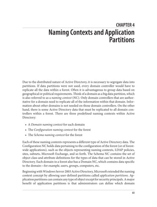
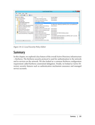
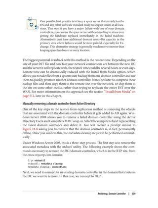
Figure 18-17.
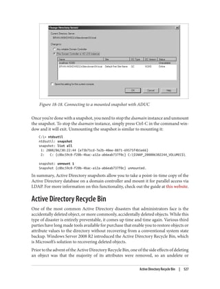
Figure 18-17. Connecting to a mounted snapshot
You can also connect to mounted snapshots using Active Directory Users and Com‐
puters:
1. Launch ADUC.
2. Right-click the domain and select Change Domain Controller
3. Select “This Domain Controller or AD LDS instance.”
4. Click “<Type a Directory Server name[:port] here>.”
5. Enter the name of a domain controller or the localhost, as shown in Figure 18-18,
and click OK.
526 | Chapter 18: Backup, Recovery, and Maintenance](https://image.slidesharecdn.com/ad-designdeploying-220718185045-afb05777/85/AD-Design-Deploying-pdf-552-320.jpg)


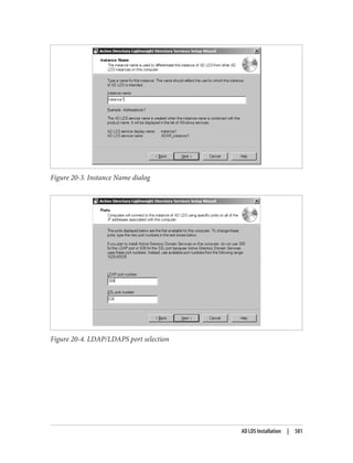

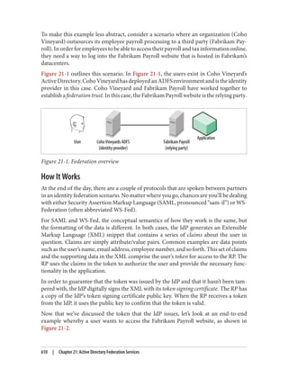


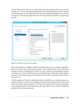
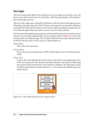
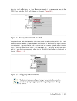
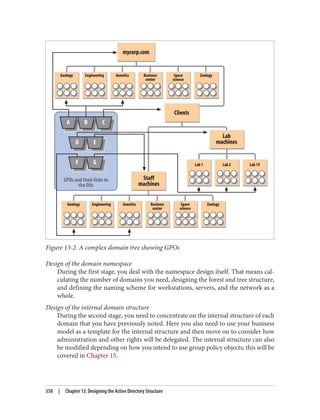
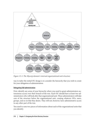
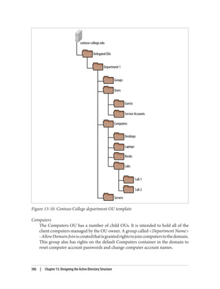
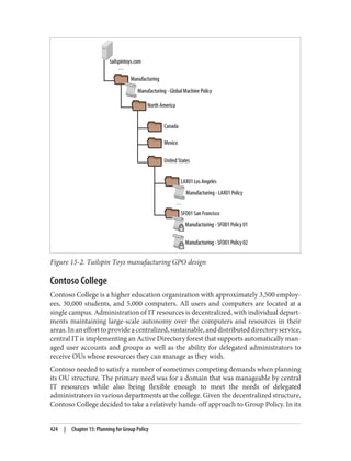
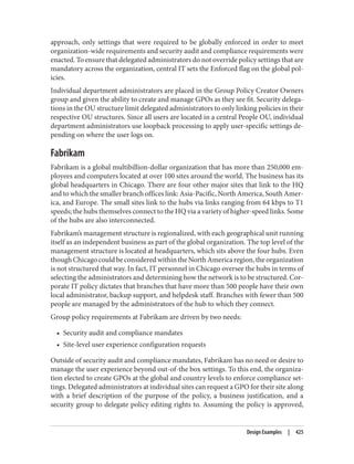
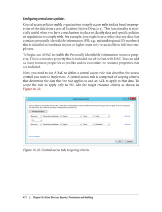
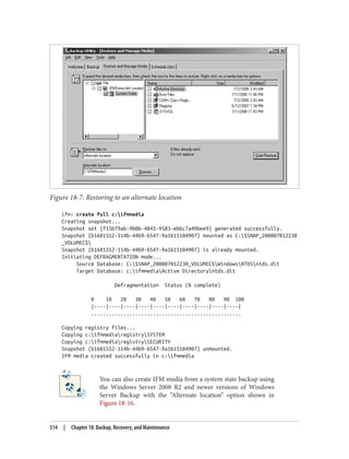
This document provides an overview of Active Directory, including: - Its basic building blocks such as domains, forests, organizational units, and the global catalog. - Tools for managing Active Directory such as Active Directory Users and Computers and LDP. - The structure and components of the Active Directory schema. - How Active Directory replication works to synchronize data between domain controllers. - Group policies and how they are used to centrally manage configurations and settings. - Authentication protocols like Kerberos that Active Directory relies on. - Best practices for designing an Active Directory structure, including naming conventions and organizational unit layouts.


