Download to read offline


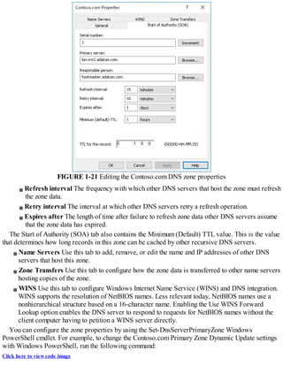
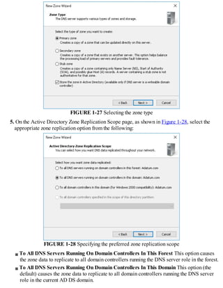
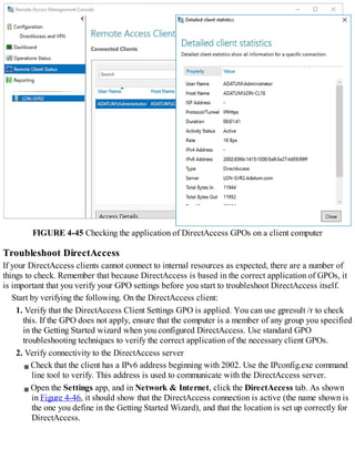
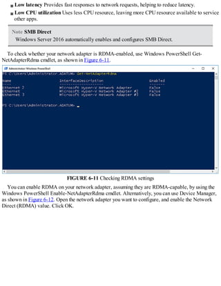
![Chapter 1. Implement Domain Name System
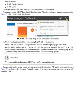
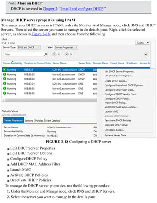
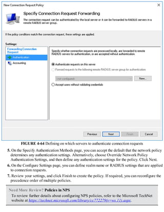
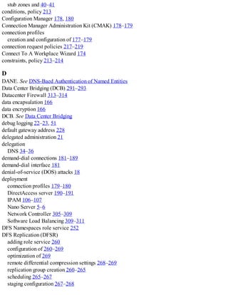
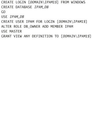
Typically, users and computers use host names rather than Internet Protocol version 4 (IPv4) or
Internet Protocol version 6 (IPv6) network addresses to communicate with other hosts and services
on networks. A Windows Server 2016 service, known as the Domain Name System (DNS) server
role, resolves these names into IPv4 or IPv6 addresses.
Since many important apps and services rely on the DNS server role, it is important that you know
how to install and configure Windows Server 2016 name resolution using the DNS server role. As a
result, the 70-741 Networking Windows Server 2016 exam covers how to install and configure the
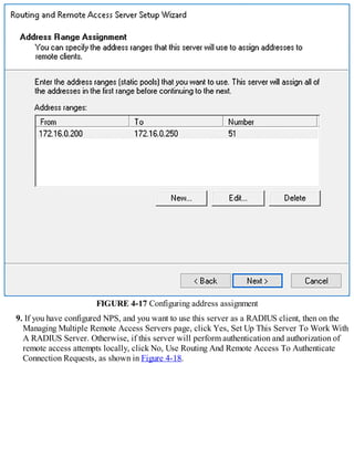
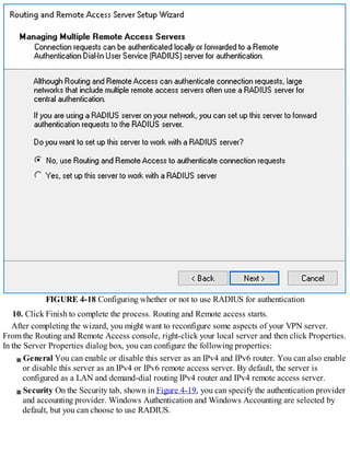
DNS server role on Windows Server 2016.
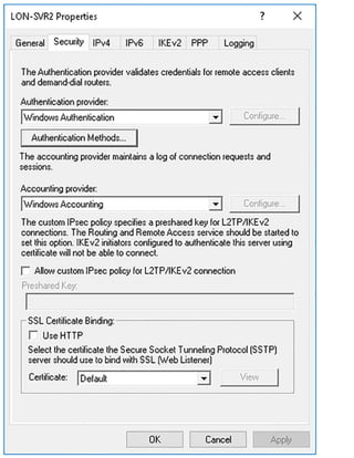
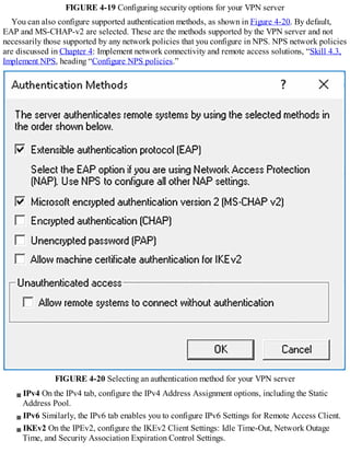
Important Have you read page xv?
It contains valuable information regarding the skills you need to pass the exam.
The 70-741 Networking Windows Server 2016 exam also covers how to implement zones and
Domain Name System records using the DNS server role. It is therefore important that you know how
to create and manage DNS zones using the Windows Server 2016 DNS server role, and how to create
and manage host and service-related records within these zones.
Skills in this chapter:
Install and configure DNS servers
Create and configure DNS zones and records
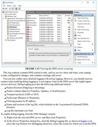
Skill 1.1: Install and configure DNS servers
Windows Server 2016 provides the DNS server role to enable you to provide name resolution
services to devices and computers in your organization’s network infrastructure. The first stage to
provide name resolution is to deploy the DNS server role on Windows Server 2016 server
computers.
Overview of name resolution
Although IP addressing is not especially complex, it is easier for users to work with host names
rather than with the IPv4 or IPv6 addresses of hosts, such as websites, to which they want to connect.
When an application, such as Microsoft Edge, references a website name, the name in the URL is
converted into the underlying IPv4 or IPv6 address using a process known as name resolution.
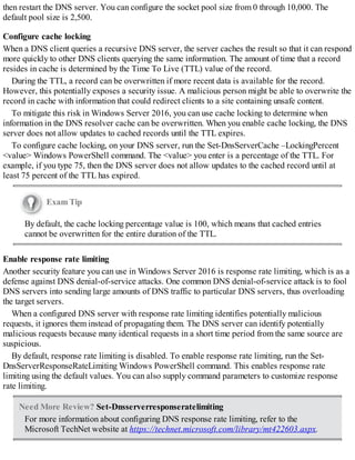
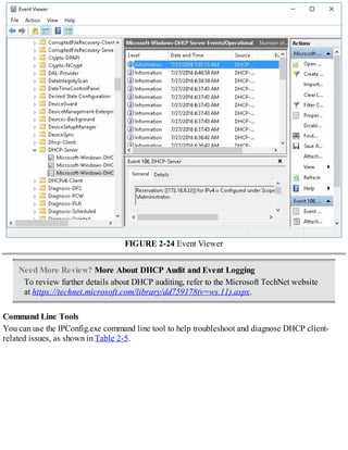
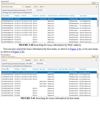
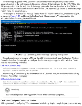
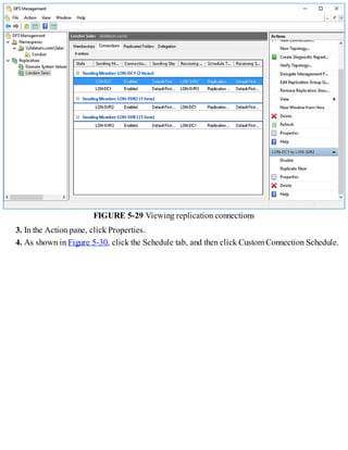
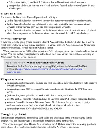
Windows 10 and Windows Server 2016 computers can use two types of names. These are:
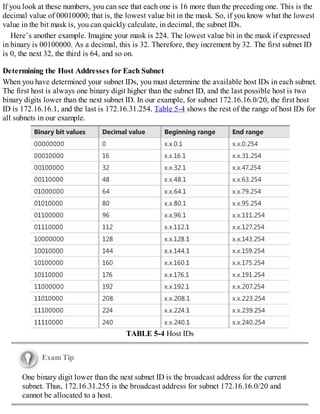
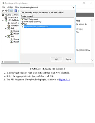
Host names A host name, up to 255 characters in length, contains only alphanumeric
characters, periods, and hyphens. A host name is an alias combined with a DNS domain name.
For example, the alias computer1, is prefixed to the domain name, Contoso.com, to create the
host name, or Fully Qualified Domain Name (FQDN), computer1.contoso.com.
NetBIOS names Less relevant today, NetBIOS names use a nonhierarchical structure based on
a 16-character name. The sixteenth character identifies a particular service running on the
computer named by the preceding 15 characters. Thus, LON-SVR1[20h] is the NetBIOS server](https://image.slidesharecdn.com/examref70-741-220718185046-4fd179d6/85/Exam-Ref-70-741-pdf-13-320.jpg)
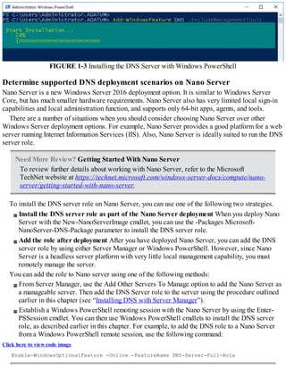
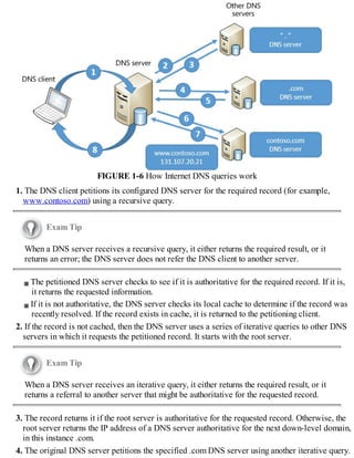
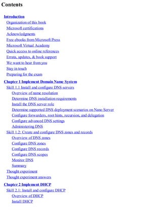
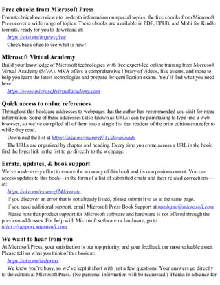
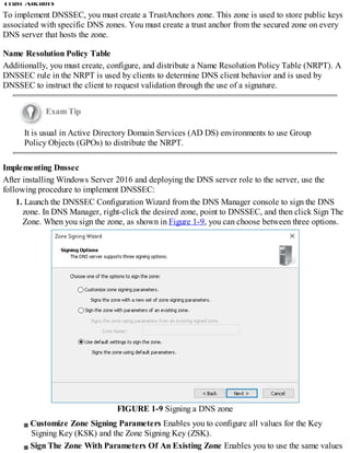
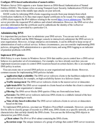
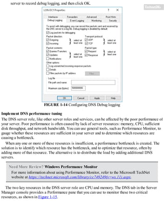
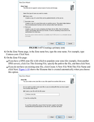
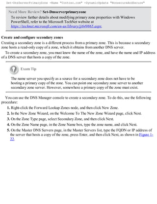
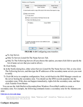
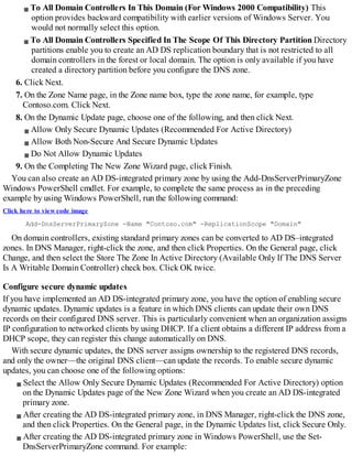
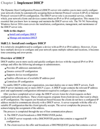
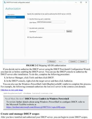
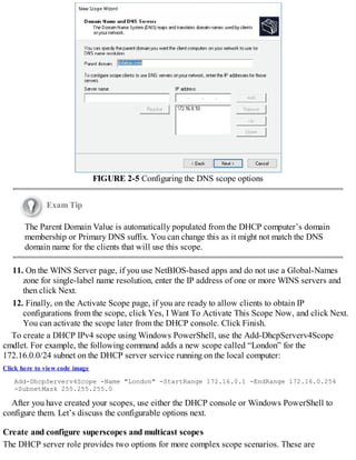
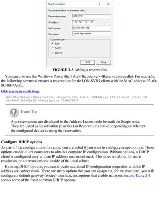
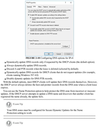
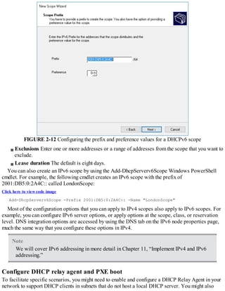
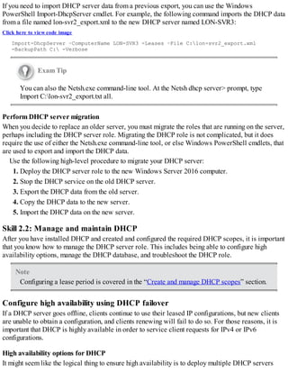
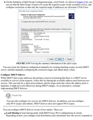
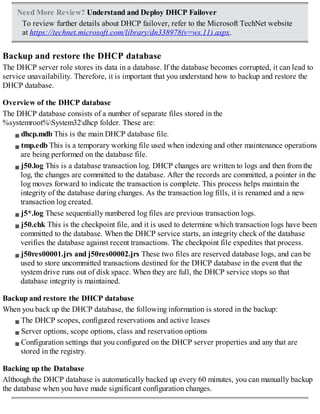
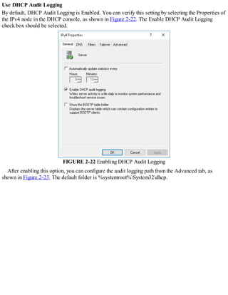
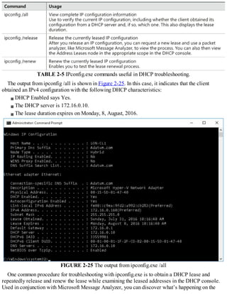
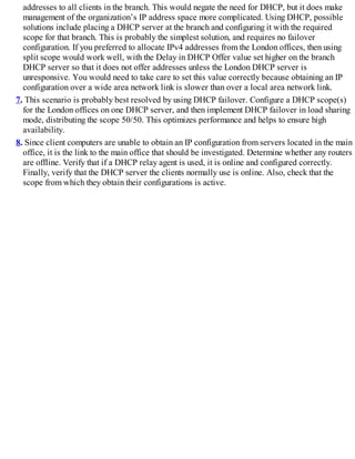
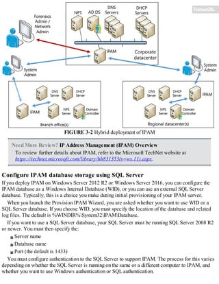
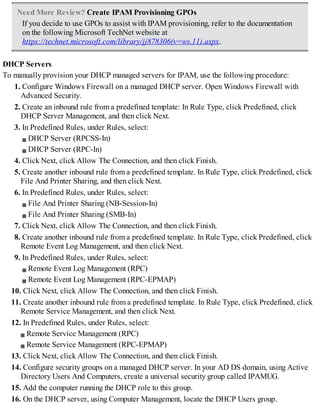
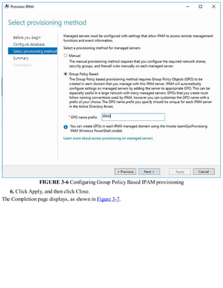
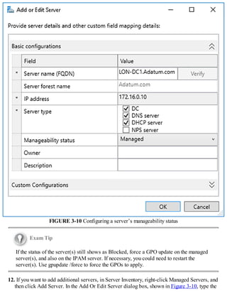
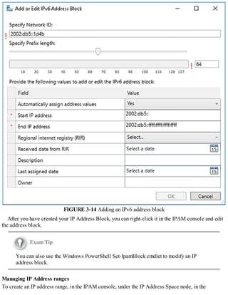
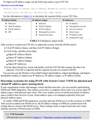
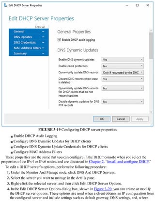
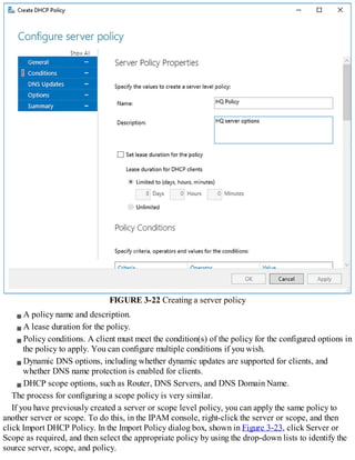
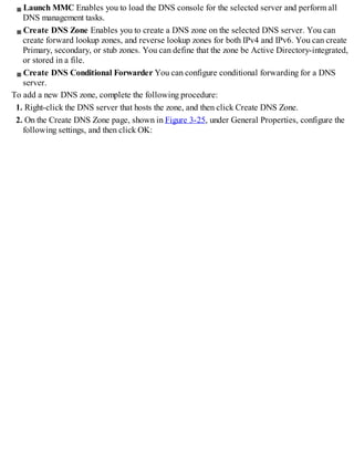
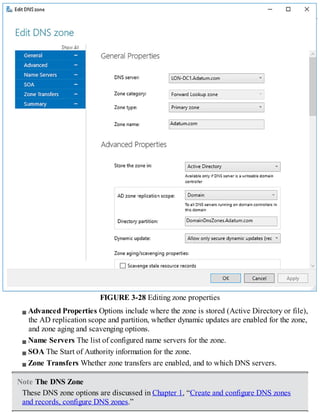
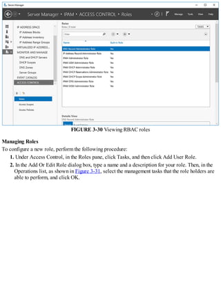
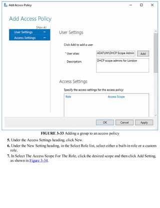
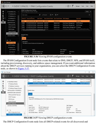
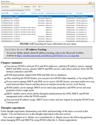
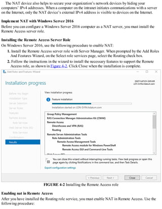
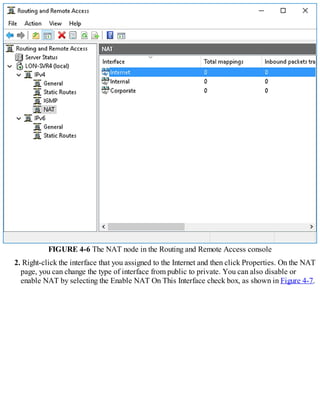
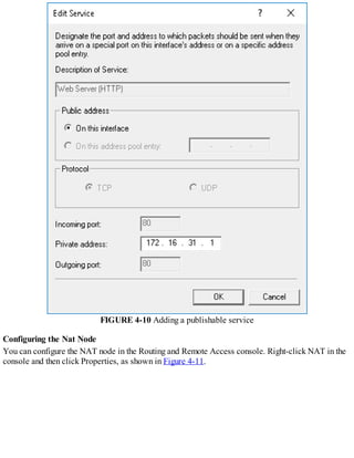
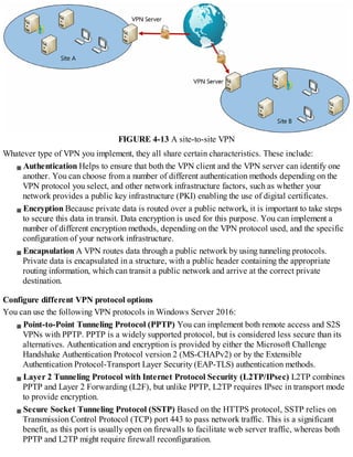
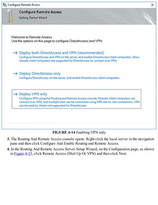
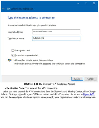
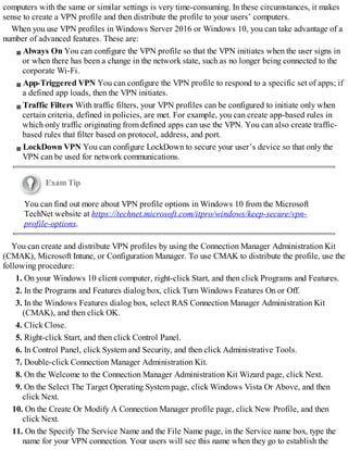
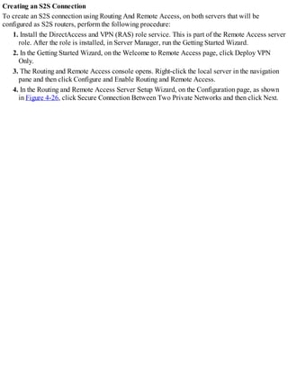
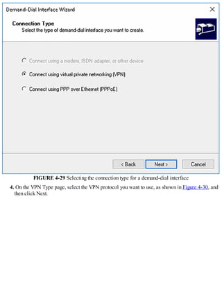
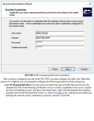
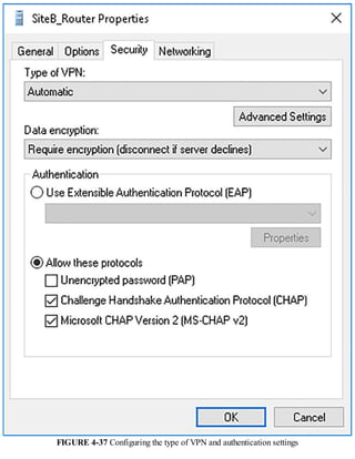
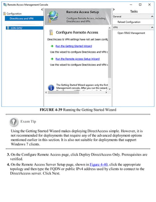
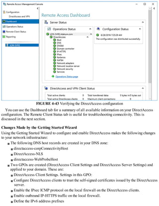
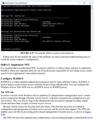
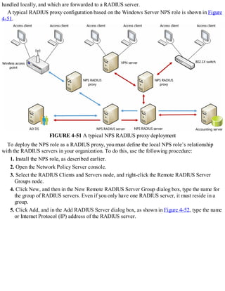
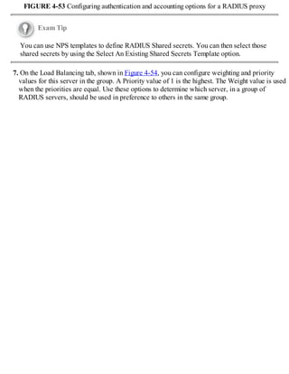
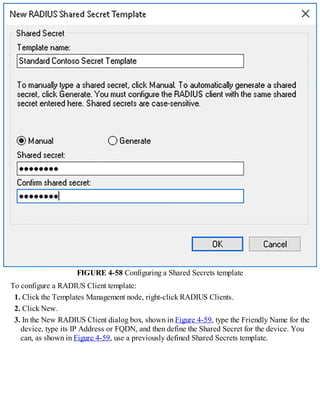
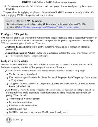
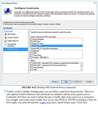
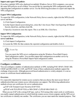
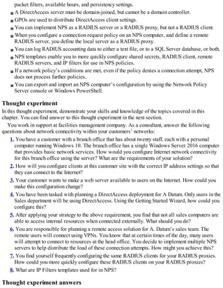
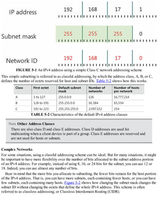
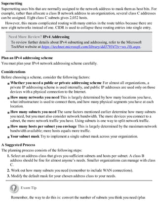
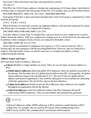
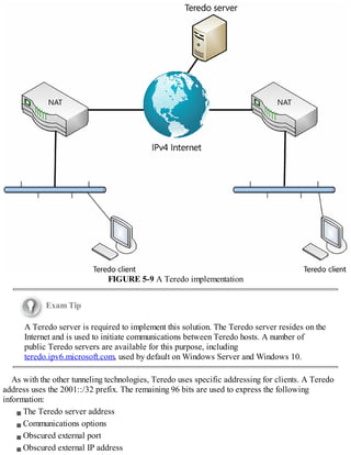
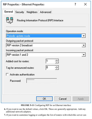
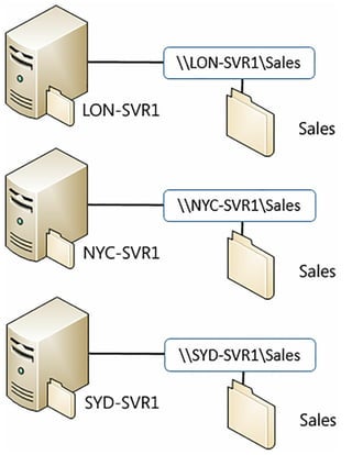
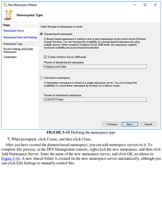
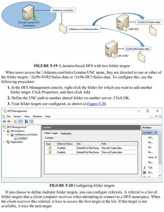
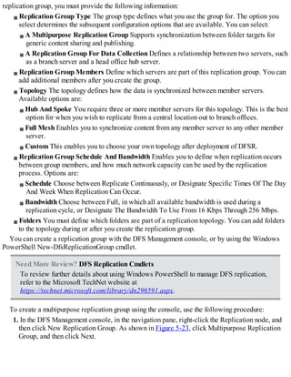
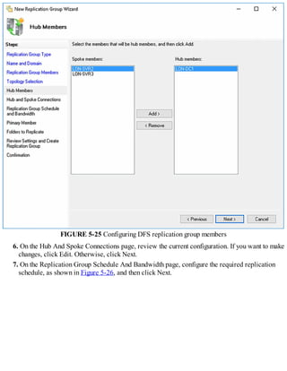
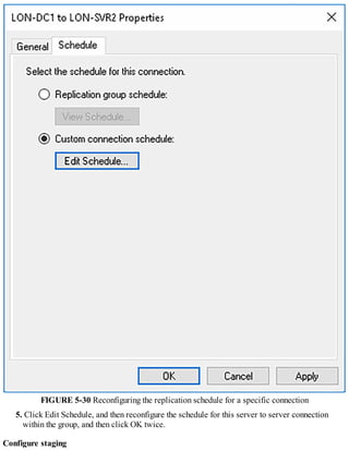
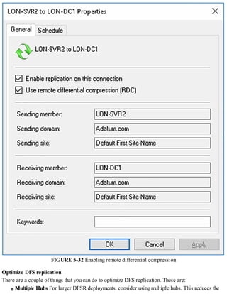
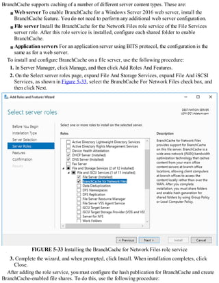
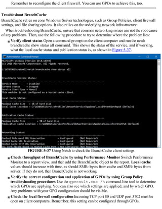
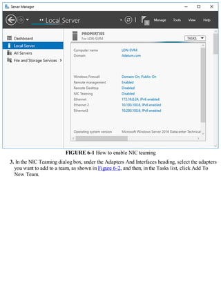
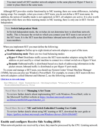
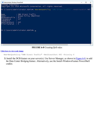
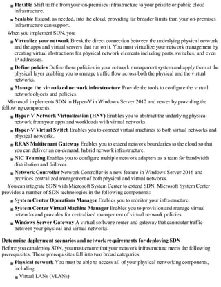
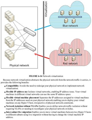
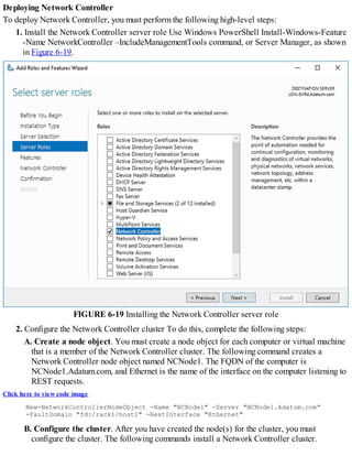
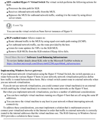
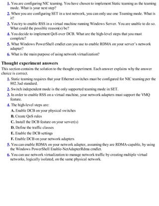
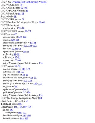
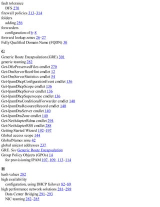
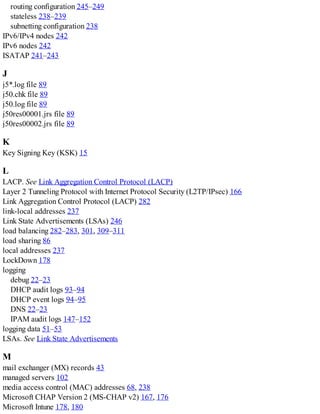
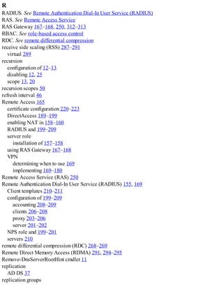
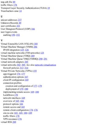
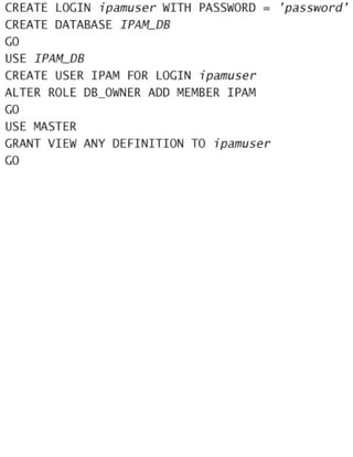
![FIGURE 1-7 Configuring root hints
4. You can then add new records, or edit or remove any existing records. You can also click
Copy From Server to import the root hints from another online DNS server. Click OK when you
have finished editing root hints.
Also, you can use Windows PowerShell to modify the root hints information on your DNS server.
The following cmdlets are available to manage root hints:
Add-DnsServerRootHint Enables you to add new root hints records.
Remove-DnsServerRootHint Enables you to delete root hints records.
Set-DnsServerRootHint Enables you to edit existing root hints records. You can also use the
Get-DnsServerRootHint cmdlet to retrieve the required record for editing.
Import-DnsServerRootHint Enables you to copy the root hints information from another
online DNS server.
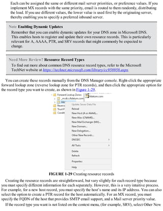
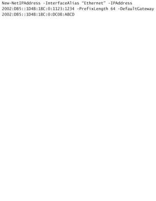
For example, to update the value for the root hints assigned to H.Root-servers.adatum.com, use the
following two Windows PowerShell commands:
Click here to view code image
$hint = (Get-DnsServerRootHint | Where-Object {$_.NameServer.RecordData.NameServer
-eq "H.Root-Servers.Adatum.com."} )
$hint.IPAddress[0].RecordData.Ipv4address = "10.24.60.254"
The first command obtains the H.Root-servers.adatum.com root hint and assigns it to the variable
$hint. The Get-DnsServerRootHint cmdlet obtains the list of all root hints, and the Where-Object
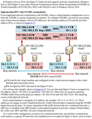
cmdlet filters the results to get only the root hint for H.Root-servers.adatum.com.](https://image.slidesharecdn.com/examref70-741-220718185046-4fd179d6/85/Exam-Ref-70-741-pdf-23-320.jpg)
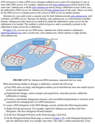
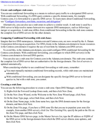
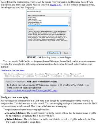

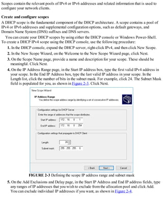
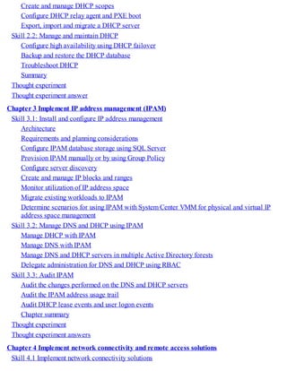
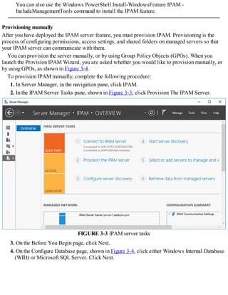
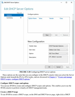
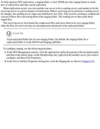
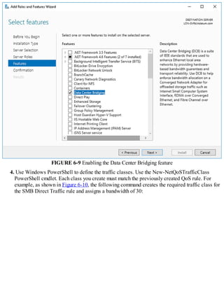
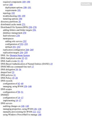
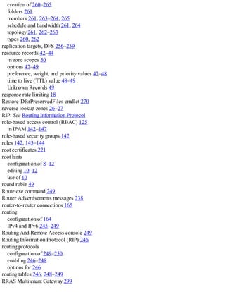
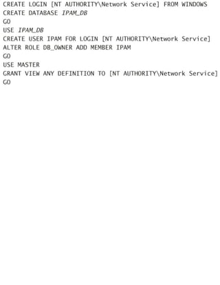
![SQL and IPAM on separate computers
To use Windows authentication, open an elevated command prompt, and run SQLCMD. Then run
the following commands (where DOMAINIPAM1$ is the AD DS domain name and the IPAM
computer name, and IPAM_DB is the name of the SQL database):
Click here to view code image
CREATE LOGIN [DOMAINIPAM1$] FROM WINDOWS
CREATE DATABASE IPAM_DB
GO
USE IPAM_DB
CREATE USER IPAM FOR LOGIN [DOMAINIPAM1$]
ALTER ROLE DB_OWNER ADD MEMBER IPAM
USE MASTER
GRANT VIEW ANY DEFINITION TO [DOMAINIPAM1$]
To use SQL authentication, at a SQLCMD prompt, run the following commands (where ipamuser
is a SQL authentication login name, ‘password’ is the SQL password for this account, and IPAM_DB
is the name of the SQL database):
Click here to view code image
CREATE LOGIN ipamuser WITH PASSWORD = 'password'
CREATE DATABASE IPAM_DB
GO
USE IPAM_DB
CREATE USER IPAM FOR LOGIN ipamuser
ALTER ROLE DB_OWNER ADD MEMBER IPAM
GO
USE MASTER
GRANT VIEW ANY DEFINITION TO ipamuser
GO
Exam Tip
The information you enter here must exactly match what you enter in the IPAM
provisioning wizard.
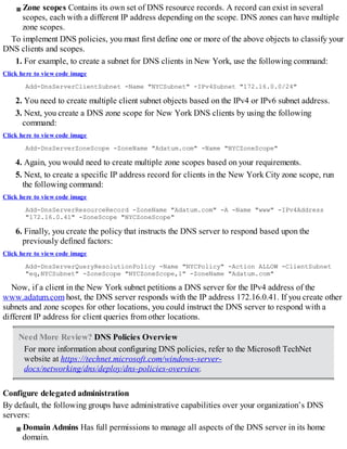
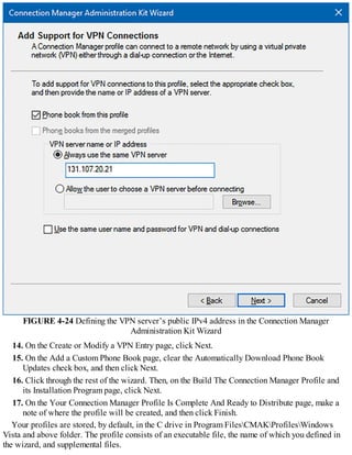
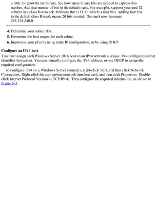
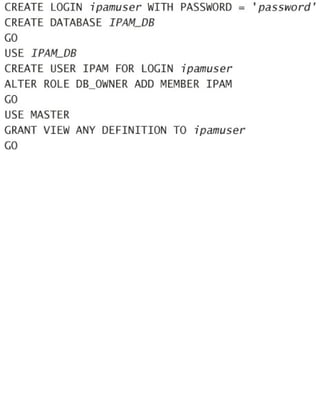
SQL and IPAM on the same computer
If SQL and IPAM are deployed on the same computer, to use Windows authentication, open an
elevated command prompt and run SQLCMD. Then run the following commands (where IPAM_DB is
the name of the SQL database):
Click here to view code image
CREATE LOGIN [NT AUTHORITYNetwork Service] FROM WINDOWS
CREATE DATABASE IPAM_DB
GO
USE IPAM_DB
CREATE USER IPAM FOR LOGIN [NT AUTHORITYNetwork Service]
ALTER ROLE DB_OWNER ADD MEMBER IPAM
GO
USE MASTER](https://image.slidesharecdn.com/examref70-741-220718185046-4fd179d6/85/Exam-Ref-70-741-pdf-116-320.jpg)
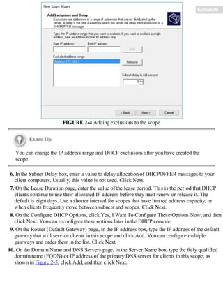
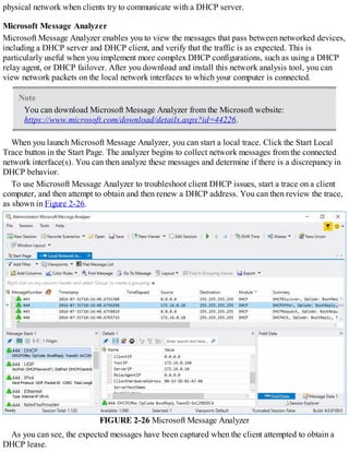
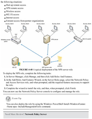
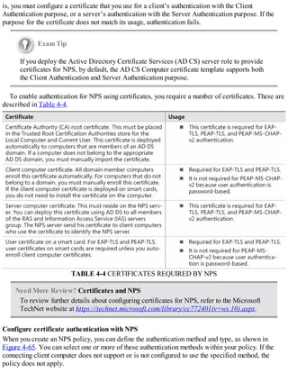
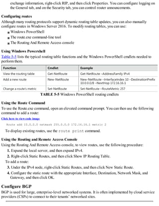
![GRANT VIEW ANY DEFINITION TO [NT AUTHORITYNetwork Service]
GO
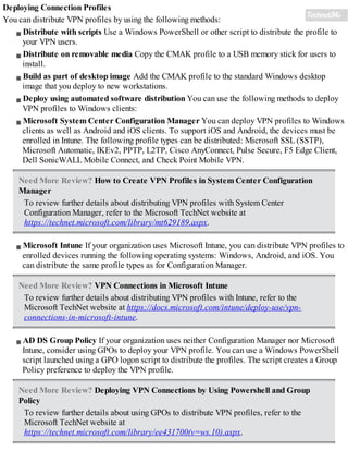
To use SQL authentication, at a SQLCMD prompt, run the following commands (where ipamuser
is a SQL authentication login name, ‘password’ is the SQL password for this account, and IPAM_DB
is the name of the SQL database).
Click here to view code image
CREATE LOGIN ipamuser WITH PASSWORD = 'password'
CREATE DATABASE IPAM_DB
GO
USE IPAM_DB
CREATE USER IPAM FOR LOGIN ipamuser
ALTER ROLE DB_OWNER ADD MEMBER IPAM
GO
USE MASTER
GRANT VIEW ANY DEFINITION TO ipamuser
GO
Exam Tip
The information you enter here must exactly match what you enter in the IPAM
provisioning wizard.
Need More Review? Configure The SQL Database for IPAM
To review further details about the SQL Server database for IPAM, refer to the
Microsoft TechNet website at
https://technet.microsoft.com/library/dn758115(v=ws.11).aspx.
Provision IPAM manually or by using Group Policy
Before you can begin using IPAM, you must deploy and then provision the IPAM service.
Deploying IPAM
You can use Windows PowerShell or Server Manager to deploy the IPAM feature. To install the
feature using Server Manager, use the following procedure:
1. In Server Manager, click Manage, and then click Add Roles And Features.
2. Click through the Add Roles And Features Wizard, and then, on the Select Features page, select
the IP Address Management (IPAM) Server check box.
3. In the Add Features That Are Required For IP Address Management (IPAM) Server? dialog
box, click Add Features, and then click Next.
4. Click Install and when the feature has finished installing, click Close.
Exam Tip](https://image.slidesharecdn.com/examref70-741-220718185046-4fd179d6/85/Exam-Ref-70-741-pdf-117-320.jpg)


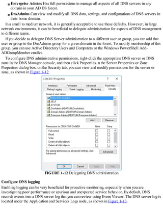
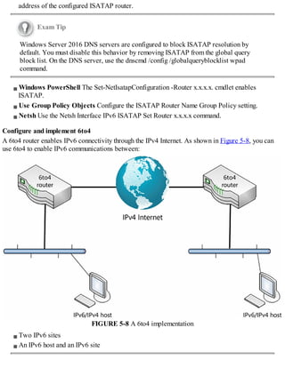
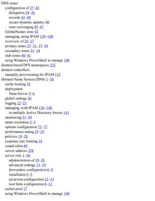
![Exam Tip
Hosts enabled with both protocols are referred to as IPv6/IPv4 nodes. Hosts configured
only with IPv4 are referred to as IPv4 nodes, while those configured only with IPv6 are
IPv6 nodes.
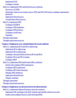
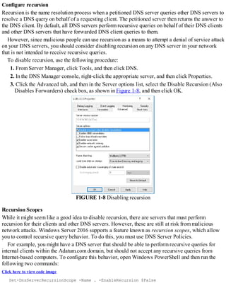
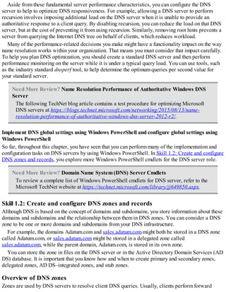
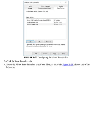
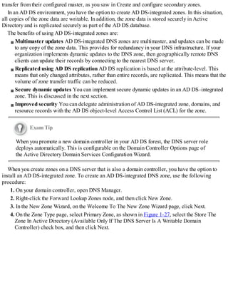
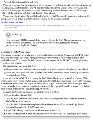
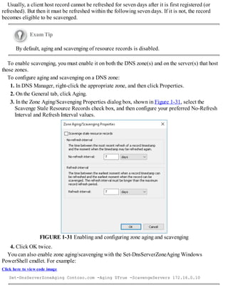
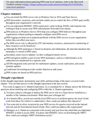
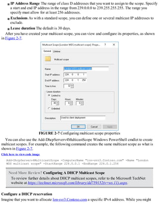
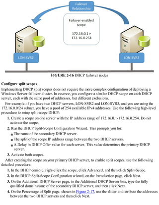
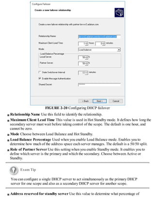
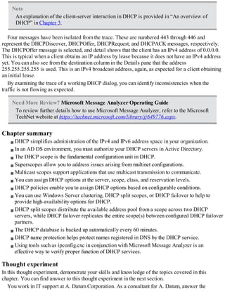
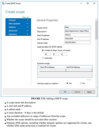
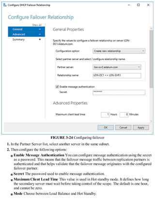
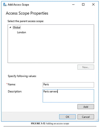
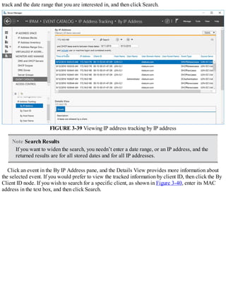
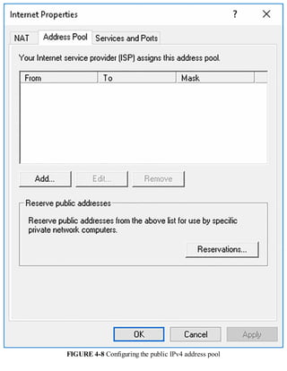
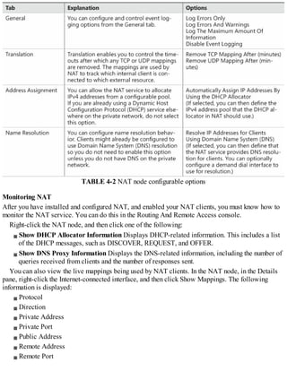
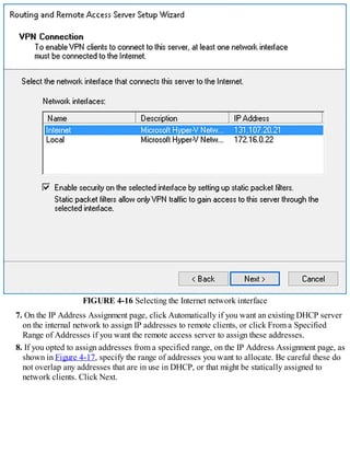
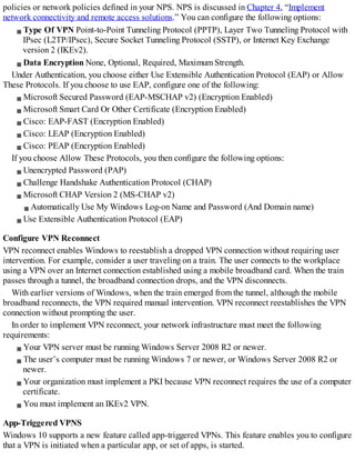
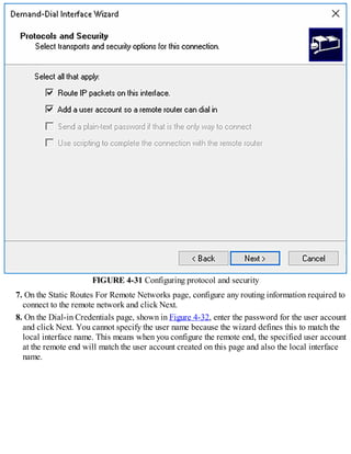
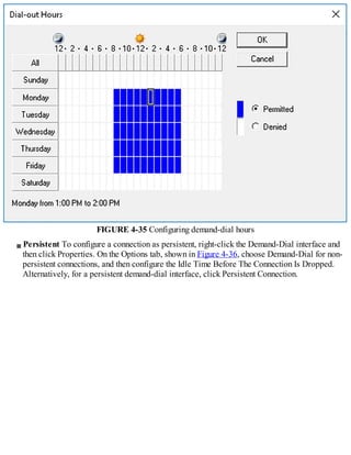
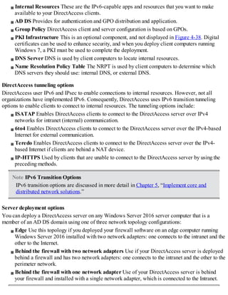
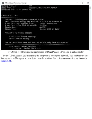
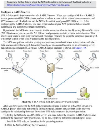
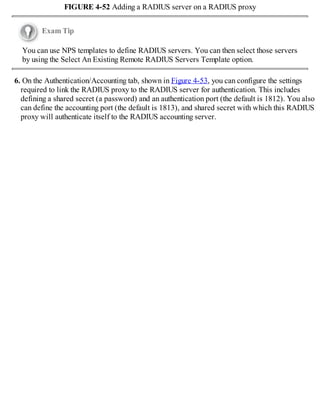
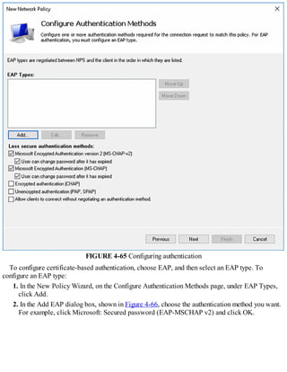
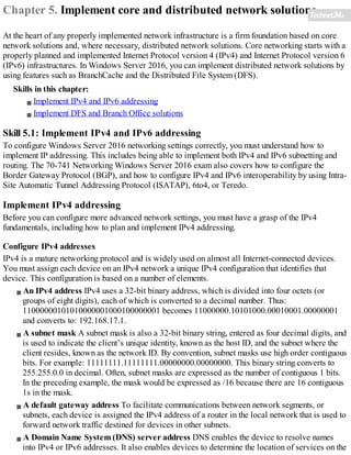
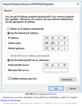
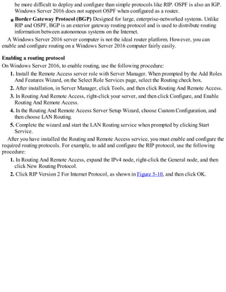
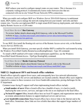
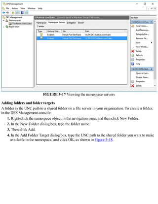
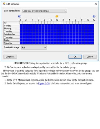
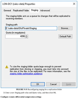
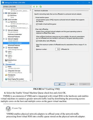
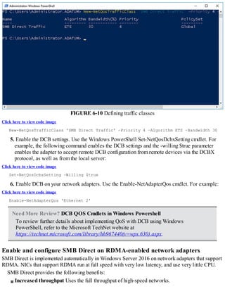
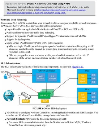
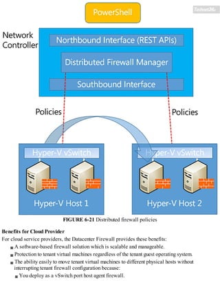
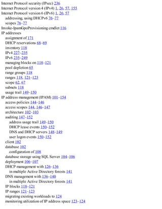
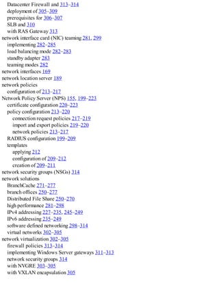
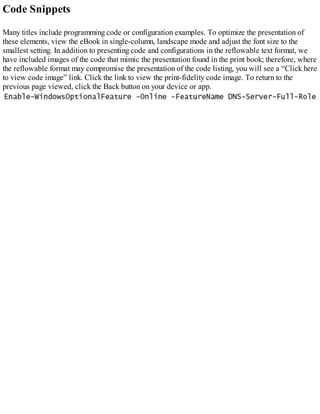
When you enable ISATAP, as shown in Figure 5-7, configured ISATAP hosts can communicate:
FIGURE 5-7 An ISATAP scenario
Over an IPv4 intranet
Through an ISATAP-configured router to IPv6 nodes on an IPv6-only network
When configured, an ISATAP host has an ISATAP address that includes its IPv4 address. If your
IPv4 hosts are using a private IP address, the IPv4 element is prefixed with 0:5EFE. Consequently, it
looks something like this: [64 bit unicast prefix]:0:5EFE:w.x.y.z.
If your hosts are using public IPv4 addresses, the IPv4 address in the ISATAP address is prefixed
with 200:5EFE. As a result, the ISATAP address looks like this: [64 bit unicast
prefix]:200:5EFE:w.x.y.z.
For example:
Based on private IPv4 address FD00::5EFE:172.16.16.10.
Based on public IPv4 address 2002:DB5::200:5EFE:131.107.16.10.
You do not need to manually configure hosts to enable ISATAP. You can rely on automatic
configuration through router advertisements. An ISATAP router advertises the required IPv6 prefix
for ISATAP hosts to use.
You can enable ISATAP using one of the following methods:
Configure an ISATAP host record in DNS This record enables clients to resolve the IPv4](https://image.slidesharecdn.com/examref70-741-220718185046-4fd179d6/85/Exam-Ref-70-741-pdf-294-320.jpg)


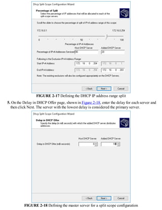
This document discusses installing and configuring the Domain Name System (DNS) server role in Windows Server 2016. It covers: 1. The basics of name resolution and how DNS works to resolve host names to IP addresses. 2. The requirements for installing the DNS server role, including supported installation scenarios on Nano Server. 3. Configuring DNS, including setting up forwarders, root hints, recursion, and delegation. 4. Administering DNS, including creating and configuring DNS zones and records to provide name resolution services. 5. Monitoring DNS to ensure it is functioning properly.


