Download as PDF, PPTX

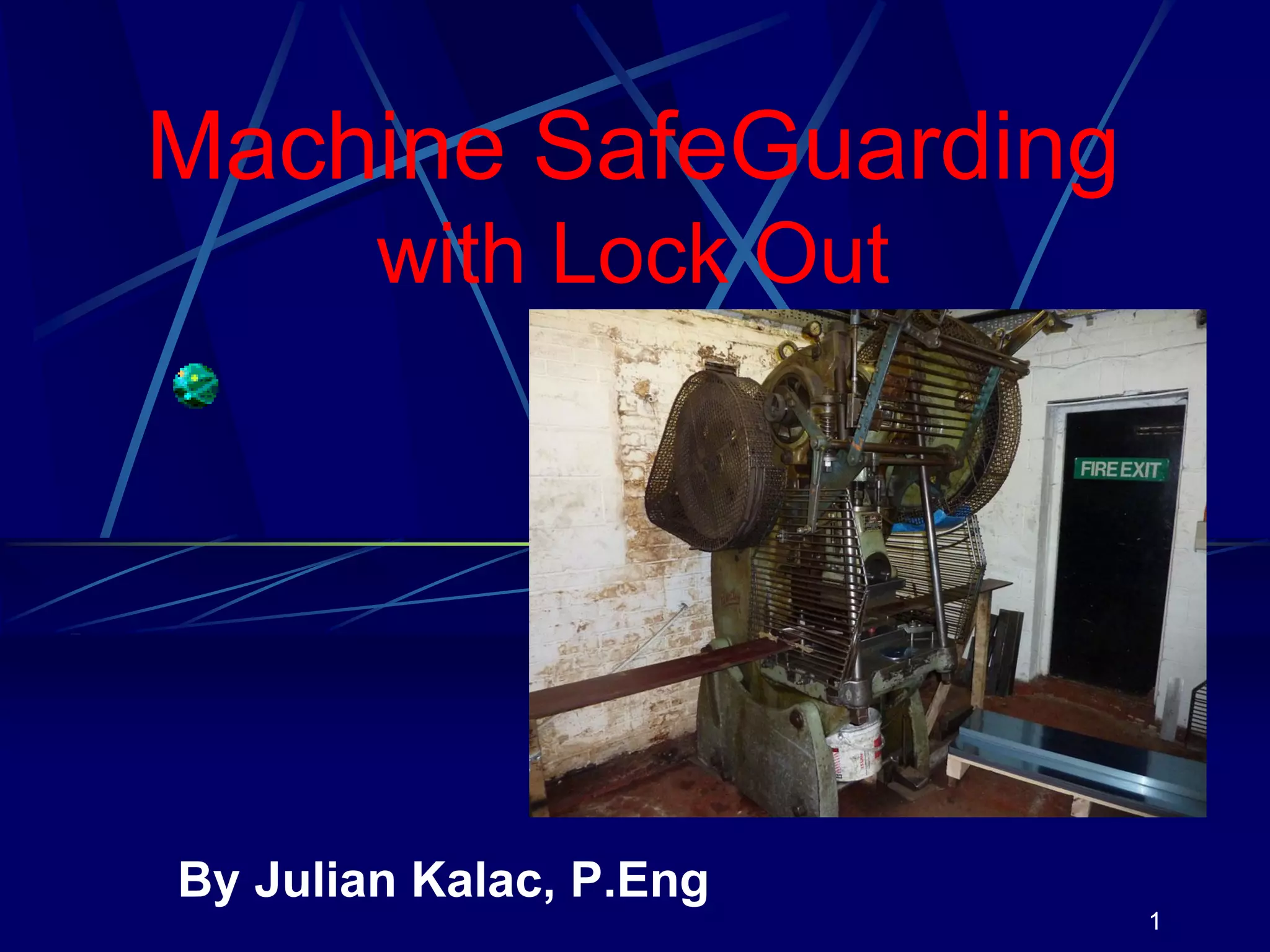

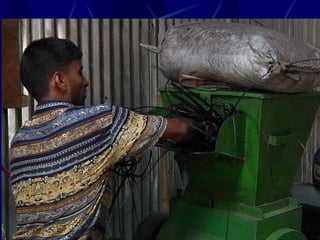


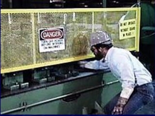
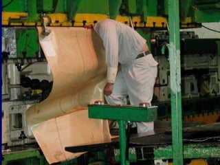
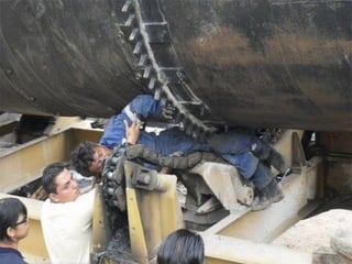
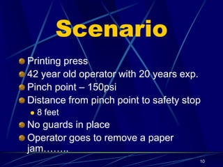
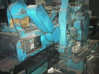
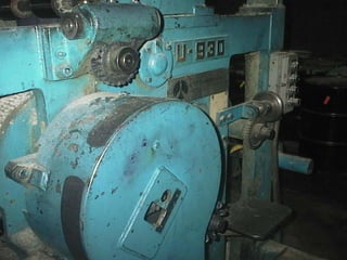
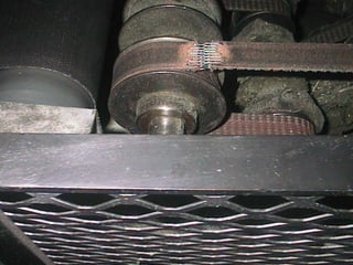
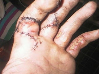
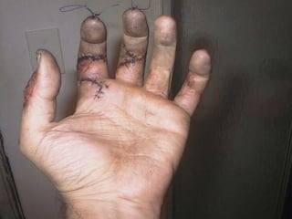
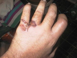


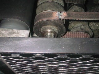

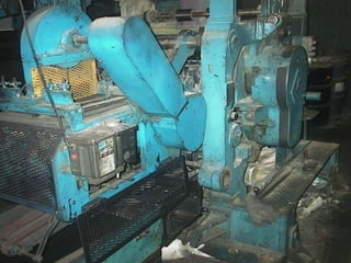
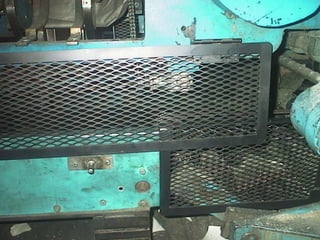
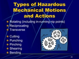
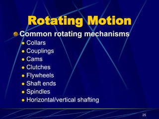
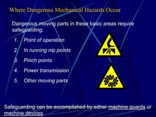
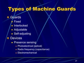
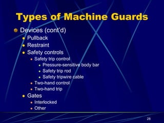
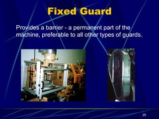
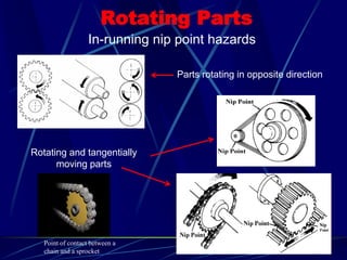
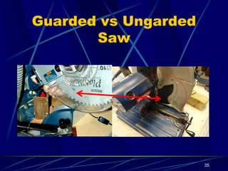
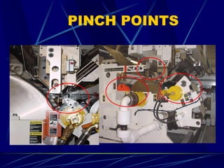
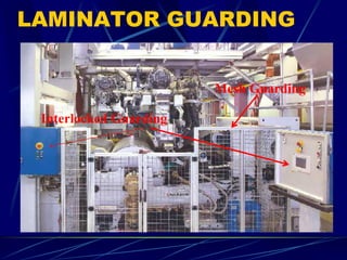
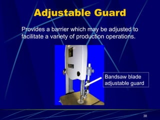
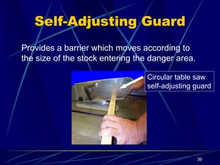
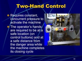
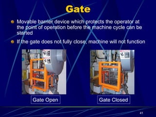
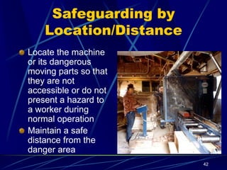
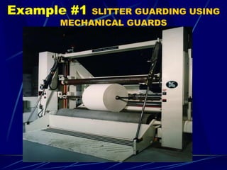
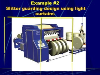
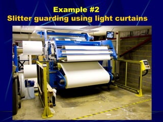
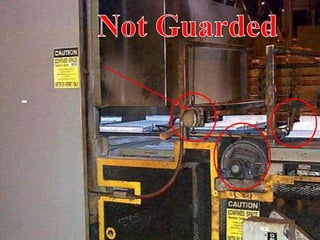
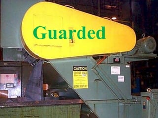
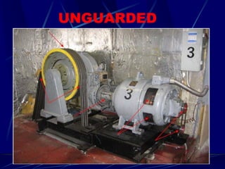
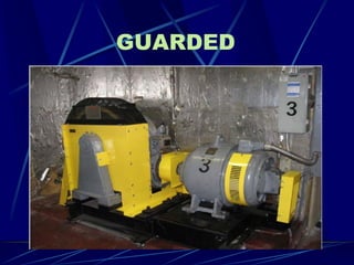
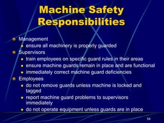


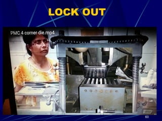

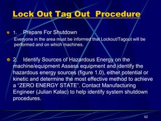

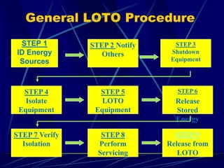
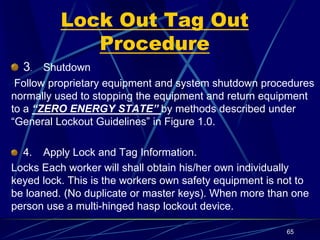


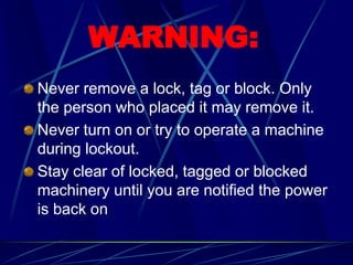
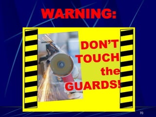
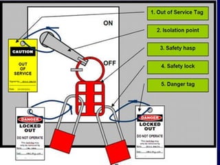


The document discusses machine safeguarding and lock out procedures. It describes a scenario where a printing press operator was injured due to unguarded pinch points. The operator was hospitalized for a week and required months of rehabilitation due to severe injuries. The document emphasizes that any machine part that could cause injury must be safeguarded. It then provides examples of different types of machine guards and safeguarding devices that can be used, such as fixed guards, interlocked guards, gates, and two-hand controls. The document stresses that proper lock out procedures are important to isolate energy sources and make machines safe for maintenance before guards can be removed.


