This document provides information on the design of a concrete beam, including:
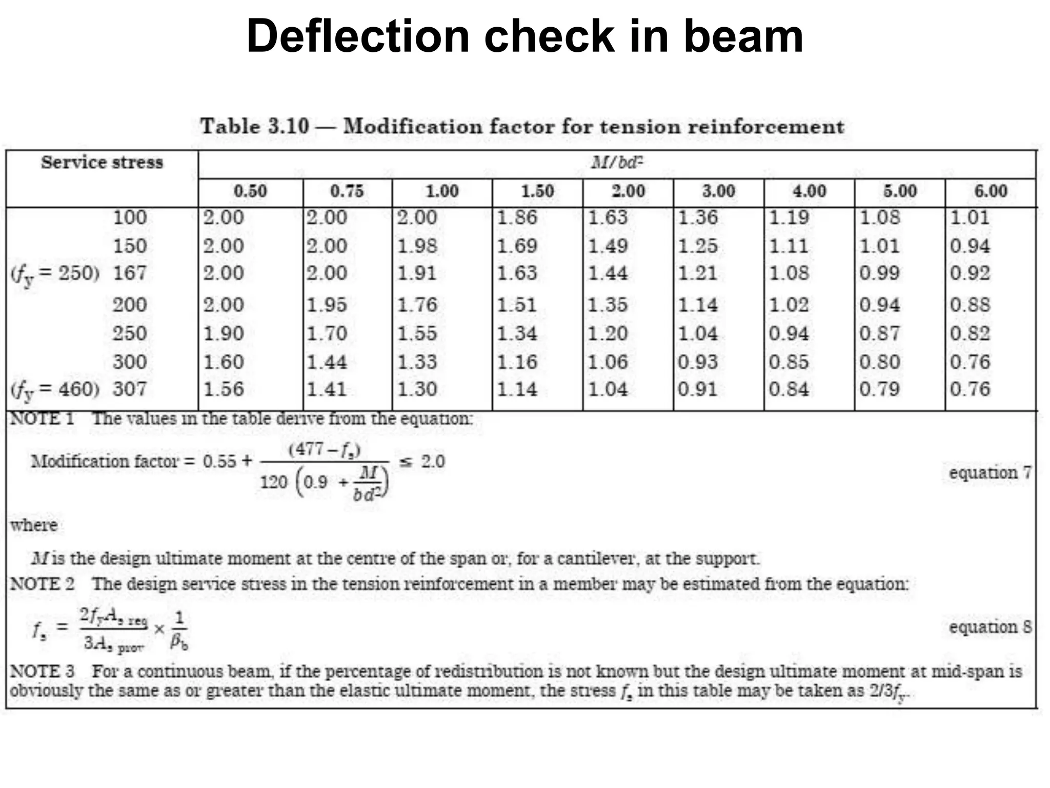
1) Key principles in beam design such as determining the effective depth ratio and performing deflection checks.
2) Details on flanged beam design including how the location of the neutral axis affects the process.
3) Procedures for continuous beam design including determining load cases, calculating fixed end moments, and using moment distribution.
Building Project (SPC1)
Designof Concrete Beam
Done by: Eng.S.Kartheepan (M.Sc, B.Eng, AMIESL, AMIIESL)
Department of Civil Engineering
IET, Katunayake
E-mail: karthee2087@gmail.com
2.
Principle in beamdesign
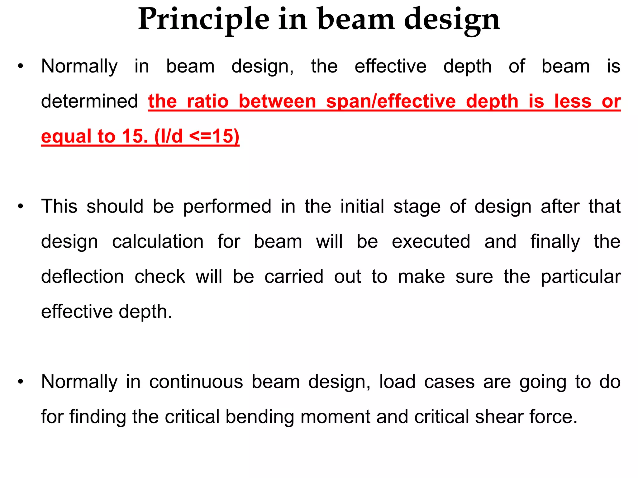
• Normally in beam design, the effective depth of beam is
determined the ratio between span/effective depth is less or
equal to 15. (l/d <=15)
• This should be performed in the initial stage of design after that
design calculation for beam will be executed and finally the
deflection check will be carried out to make sure the particular
effective depth.
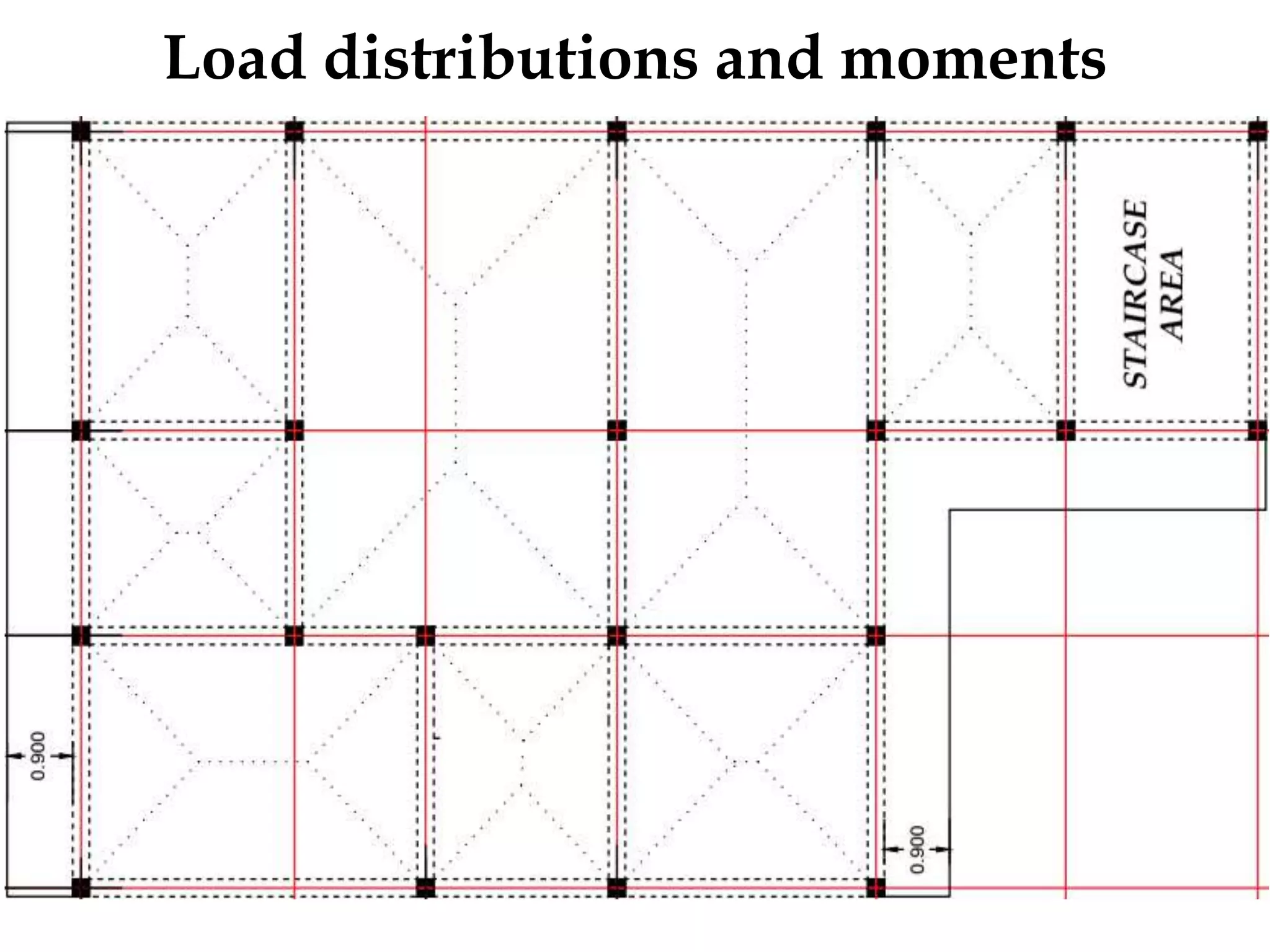
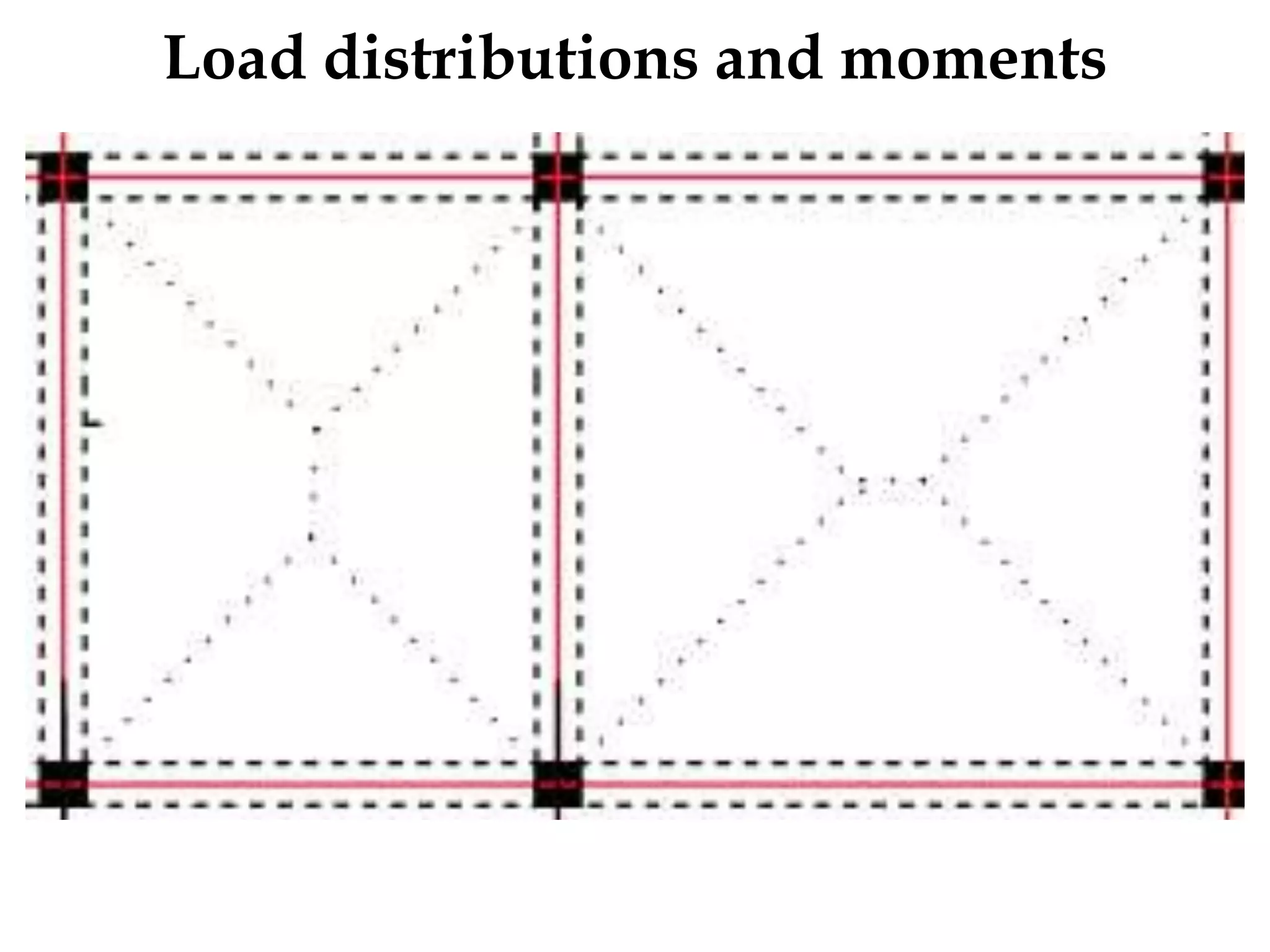
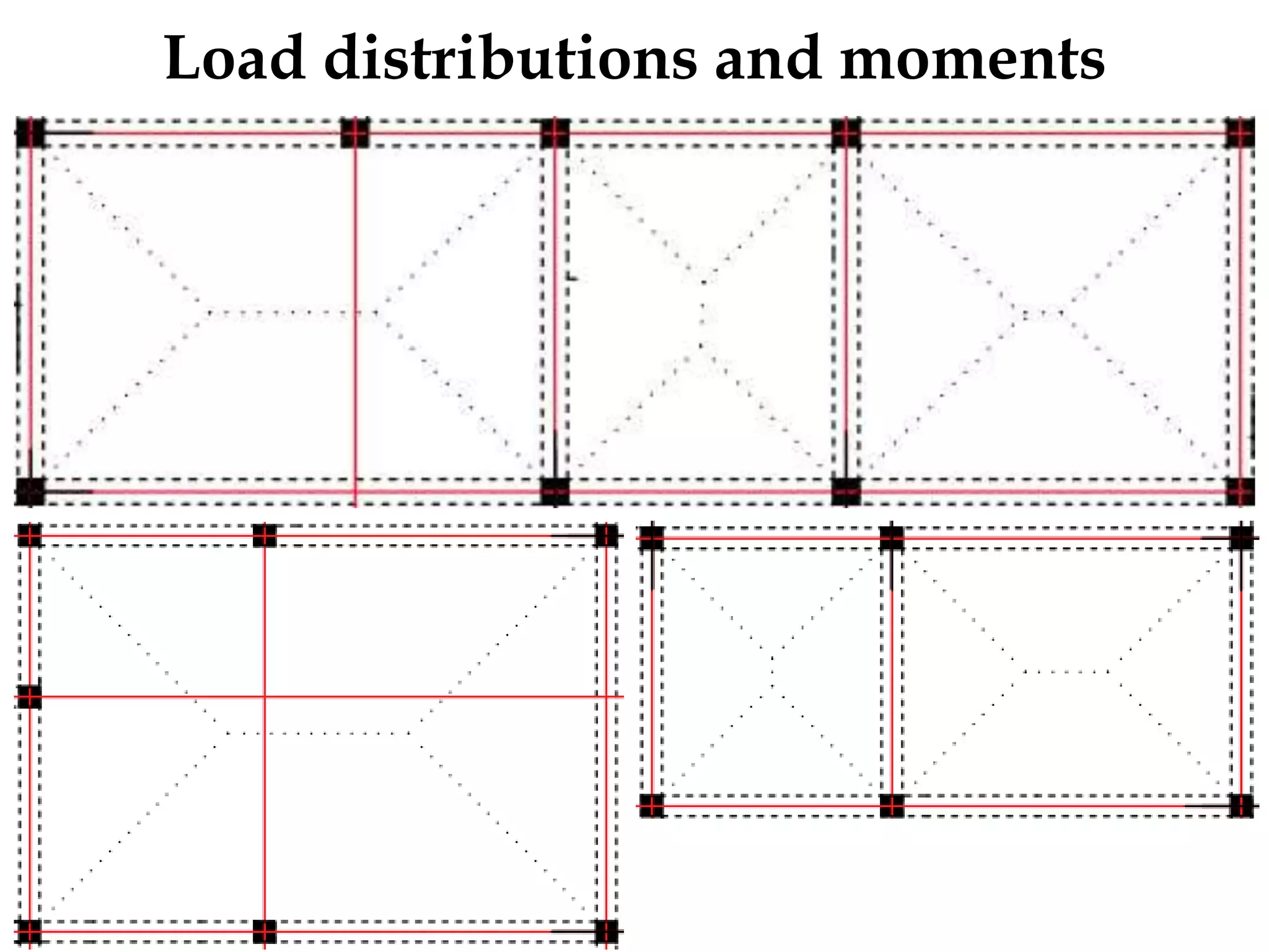
• Normally in continuous beam design, load cases are going to do
for finding the critical bending moment and critical shear force.
3.
Flanged Beam
• Thedepth of neutral axis in relation to the depth of the
flange will influence the design process.
• The neutral axis of the beam is given below
• When the neutral axis lies within the flange (hf), the
breadth of the beam at mid- span is equal to the effective
flange width (bf).
x<hf – Flanged beam action
• If x>hf then the breadth is taken as the actual width of
the beam (bw)
Effective span – for continuous beam the effective span should
normally taken as the distance between the centres of supports
Effective Flange width
Effectivewidth of flanged beam?
• The In the absence of any more accurate determination this
should be taken as:
a) for T-beams:web width + lz/5 or actual flange width
b) for L-beams:web width + lz/10 or actual flange width
Where:
• lz - is the distance between points of zero moment (which, for
a continuous beam, may be taken as 0.7 times the effective
span)
Continuous beam design
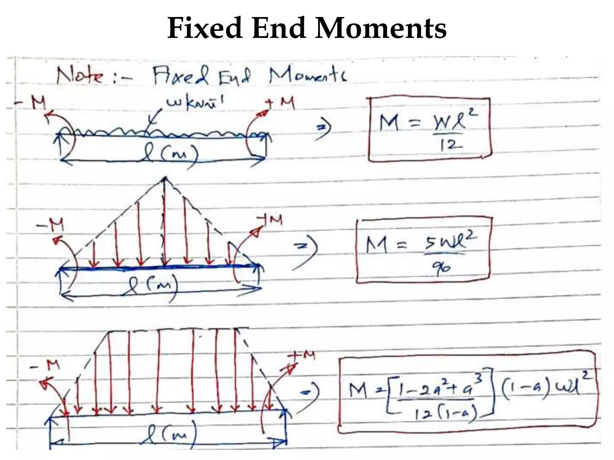
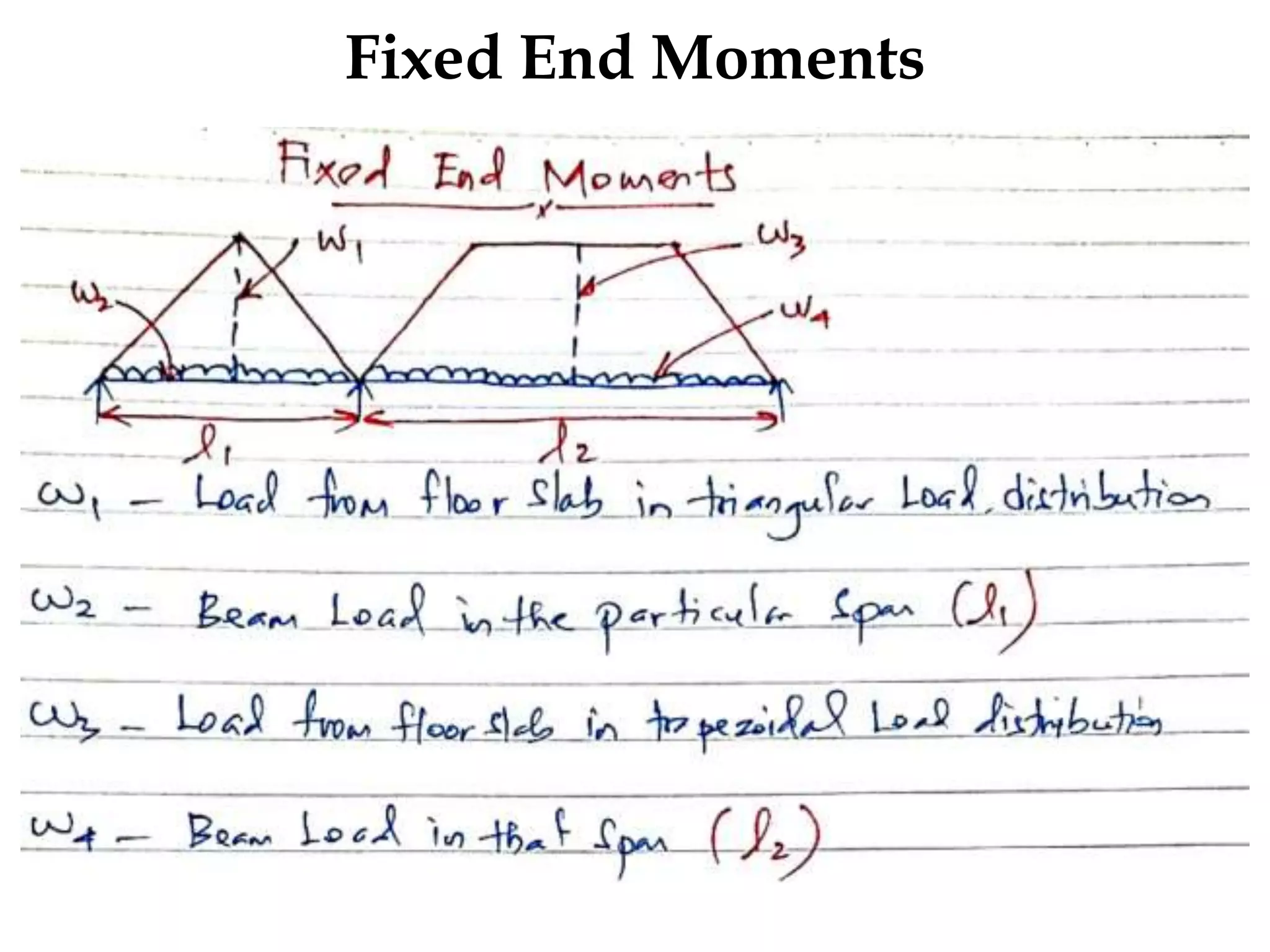
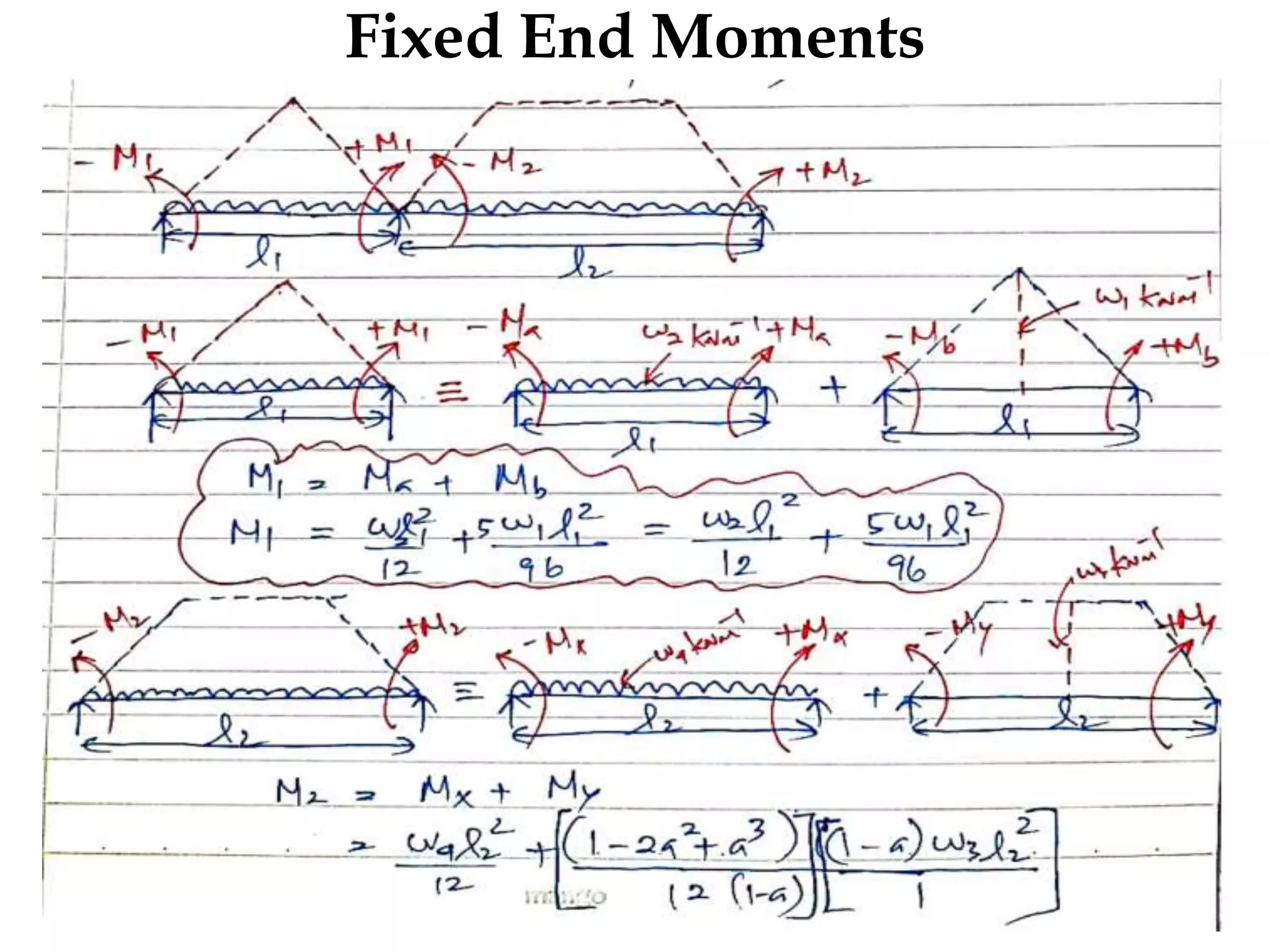
•After the finding the fixed end moments in each span of the
beam, moment distribution will be carried out to finding the
final bending moments in each cases.
• Load cases are very important to finding the final design
bending moment from all cases and also critical bending
moments and shear forces can be found.
• Moment distribution is already discussed in slab design and
follow the same approach.
16.
Principle in beamdesign
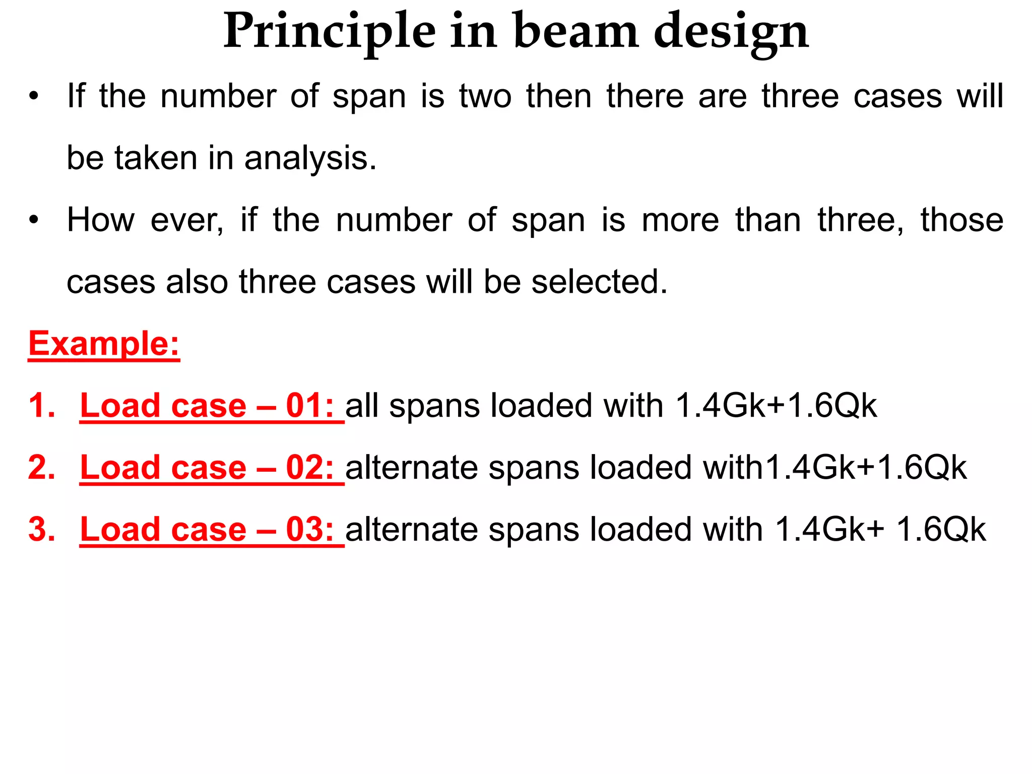
• If the number of span is two then there are three cases will
be taken in analysis.
• How ever, if the number of span is more than three, those
cases also three cases will be selected.
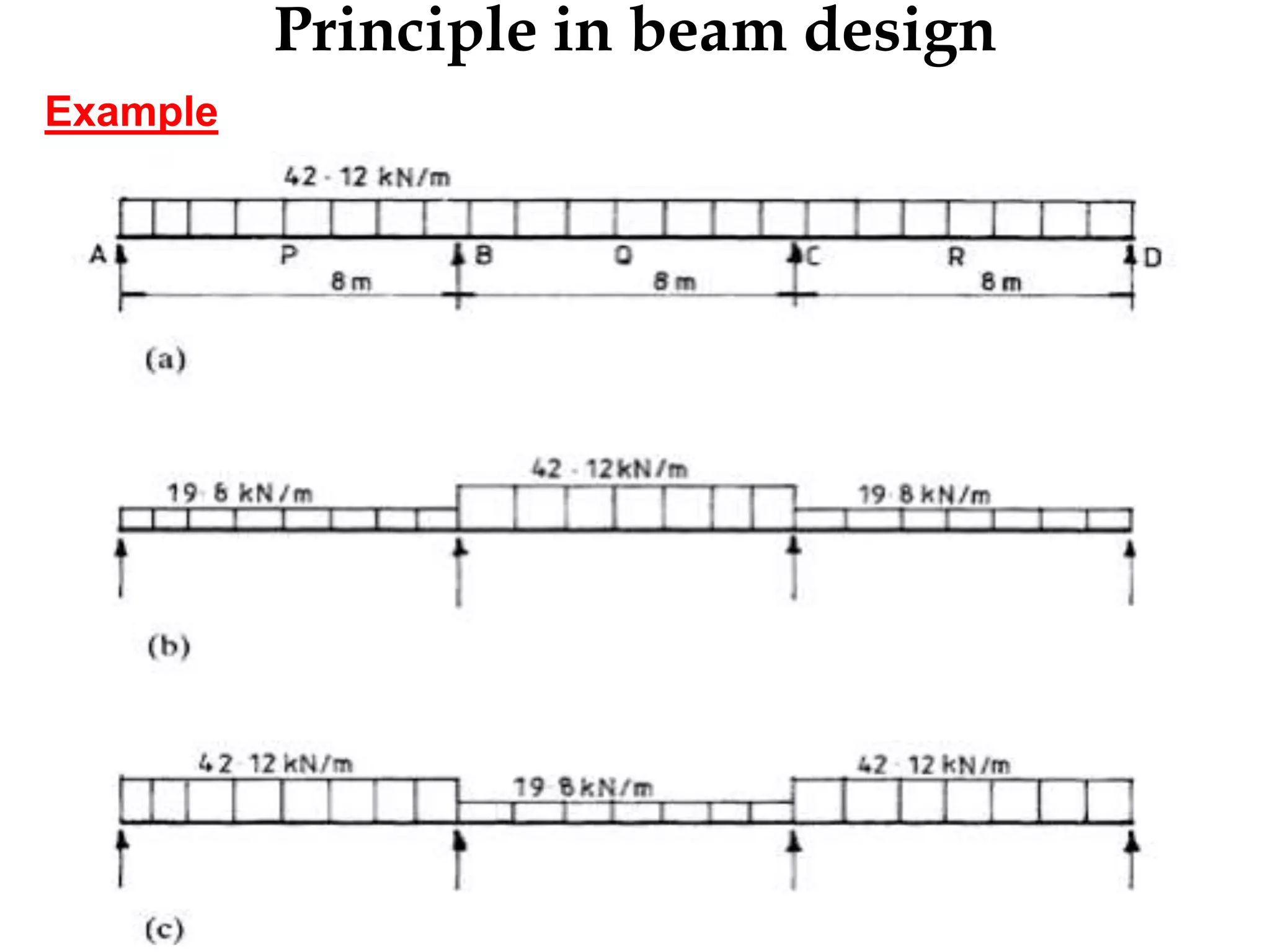
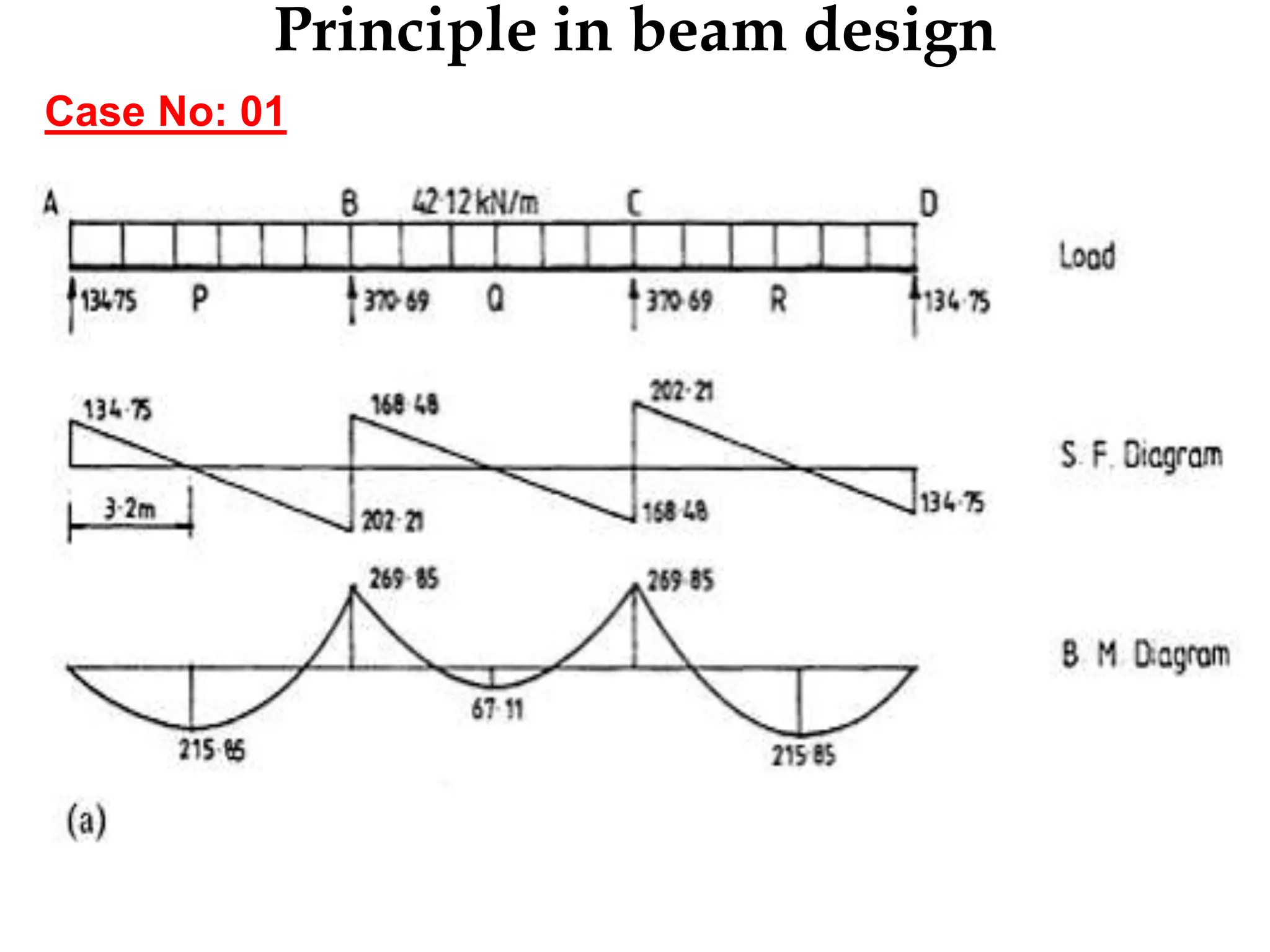
Example:
1. Load case – 01: all spans loaded with 1.4Gk+1.6Qk
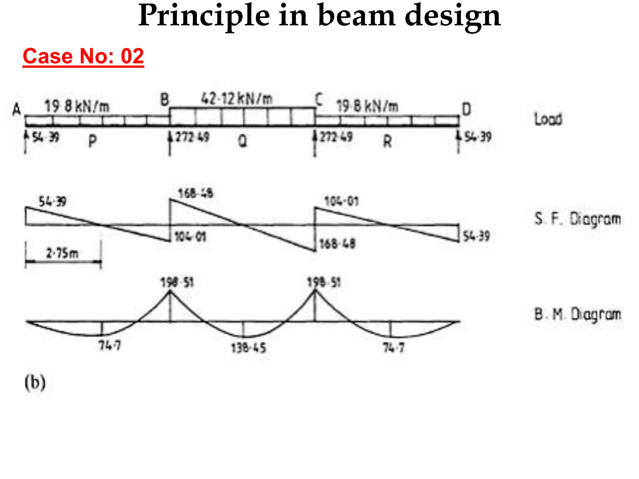
2. Load case – 02: alternate spans loaded with1.4Gk+1.6Qk
3. Load case – 03: alternate spans loaded with 1.4Gk+ 1.6Qk
Curtailment detailing inreinforcement work
Curtailment is a way of reducing the area of tensile reinforcement
at points/areas (either on a beam/slab) where bending moment is
minimum or zero for the purpose of achieving an economic
design.
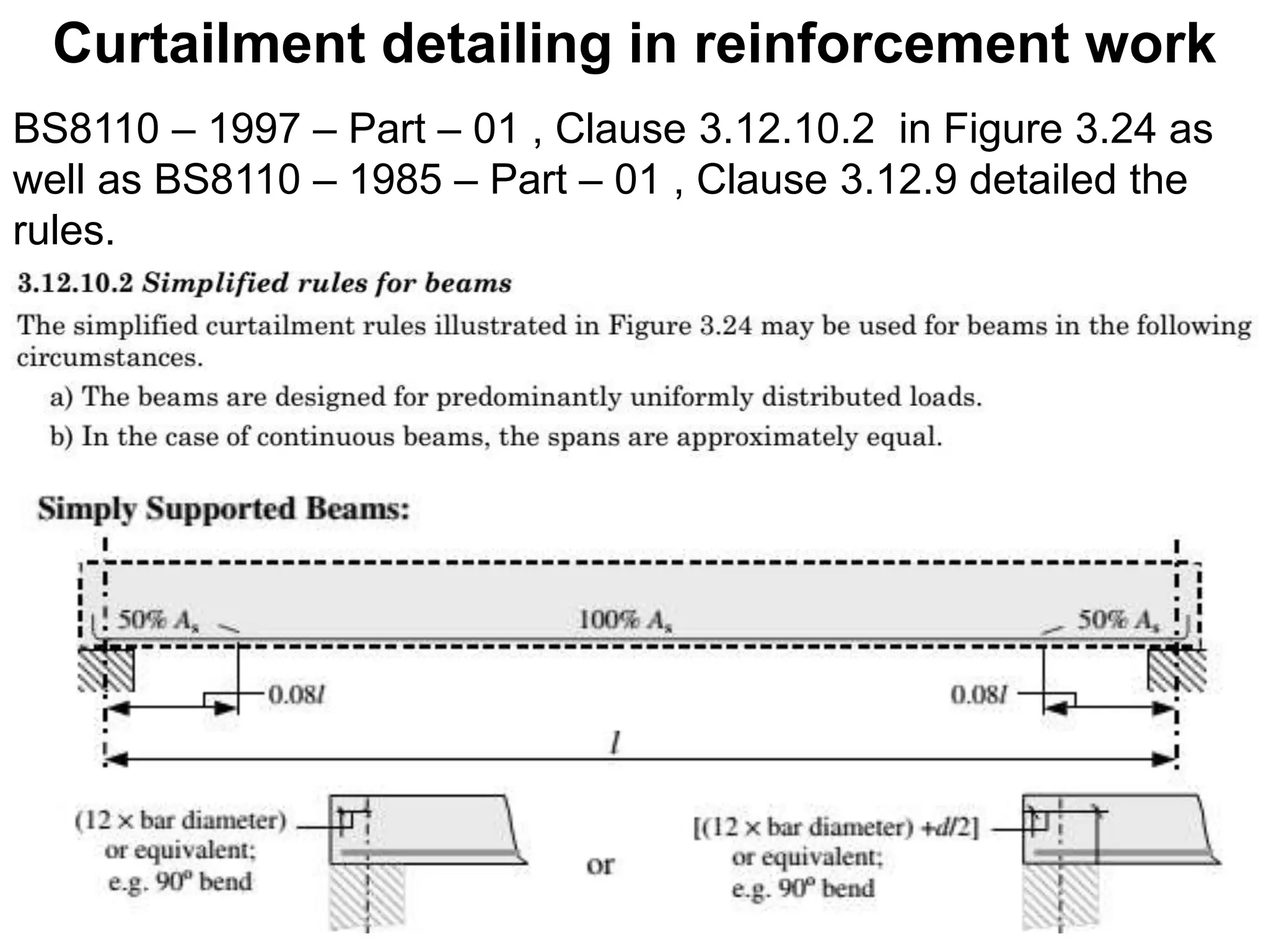
Simplified rules for beam
Curtailment of Reinforcement in Beams: Reinforcements are
curtailed along its length in beams depending on the bending
moment at the section. Anchorage or development length
required at support is provided during curtailment of
reinforcement.
40.
Curtailment detailing inreinforcement work
BS8110 – 1997 – Part – 01 , Clause 3.12.10.2 in Figure 3.24 as
well as BS8110 – 1985 – Part – 01 , Clause 3.12.9 detailed the
rules.
41.
Curtailment detailing inreinforcement work
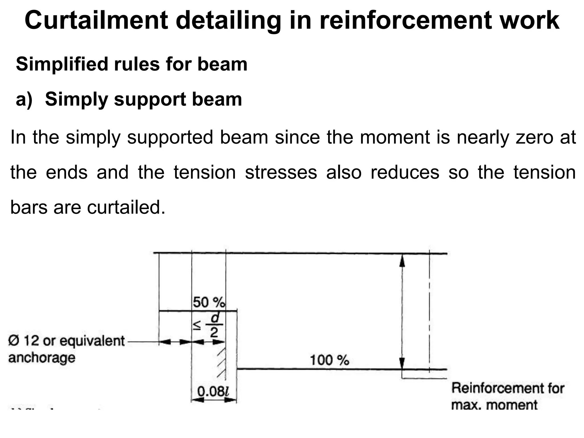
Simplified rules for beam
a) Simply support beam
In the simply supported beam since the moment is nearly zero at
the ends and the tension stresses also reduces so the tension
bars are curtailed.
42.
Curtailment detailing inreinforcement work
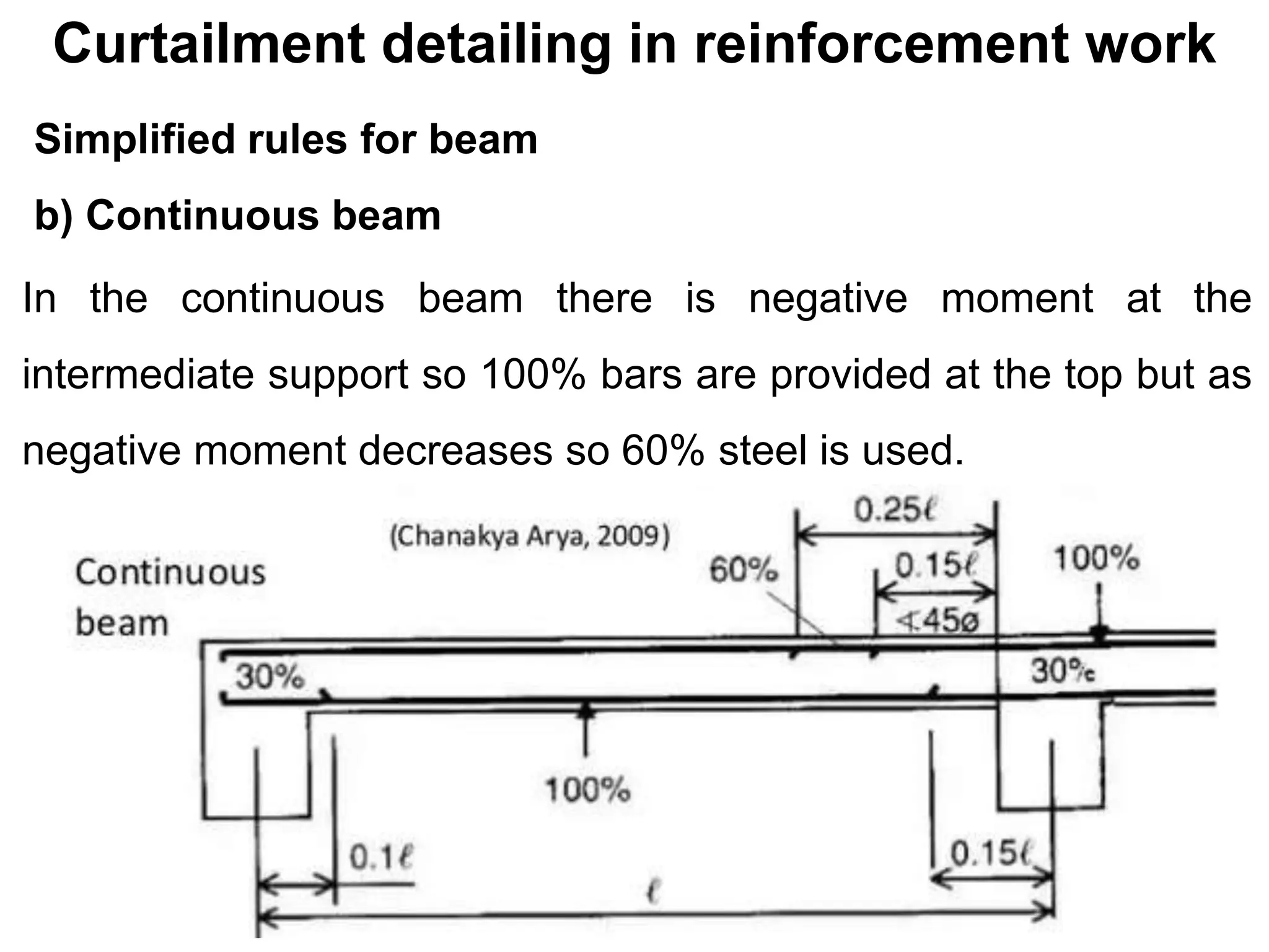
Simplified rules for beam
b) Continuous beam
In the continuous beam there is negative moment at the
intermediate support so 100% bars are provided at the top but as
negative moment decreases so 60% steel is used.
Lap Length inBeam
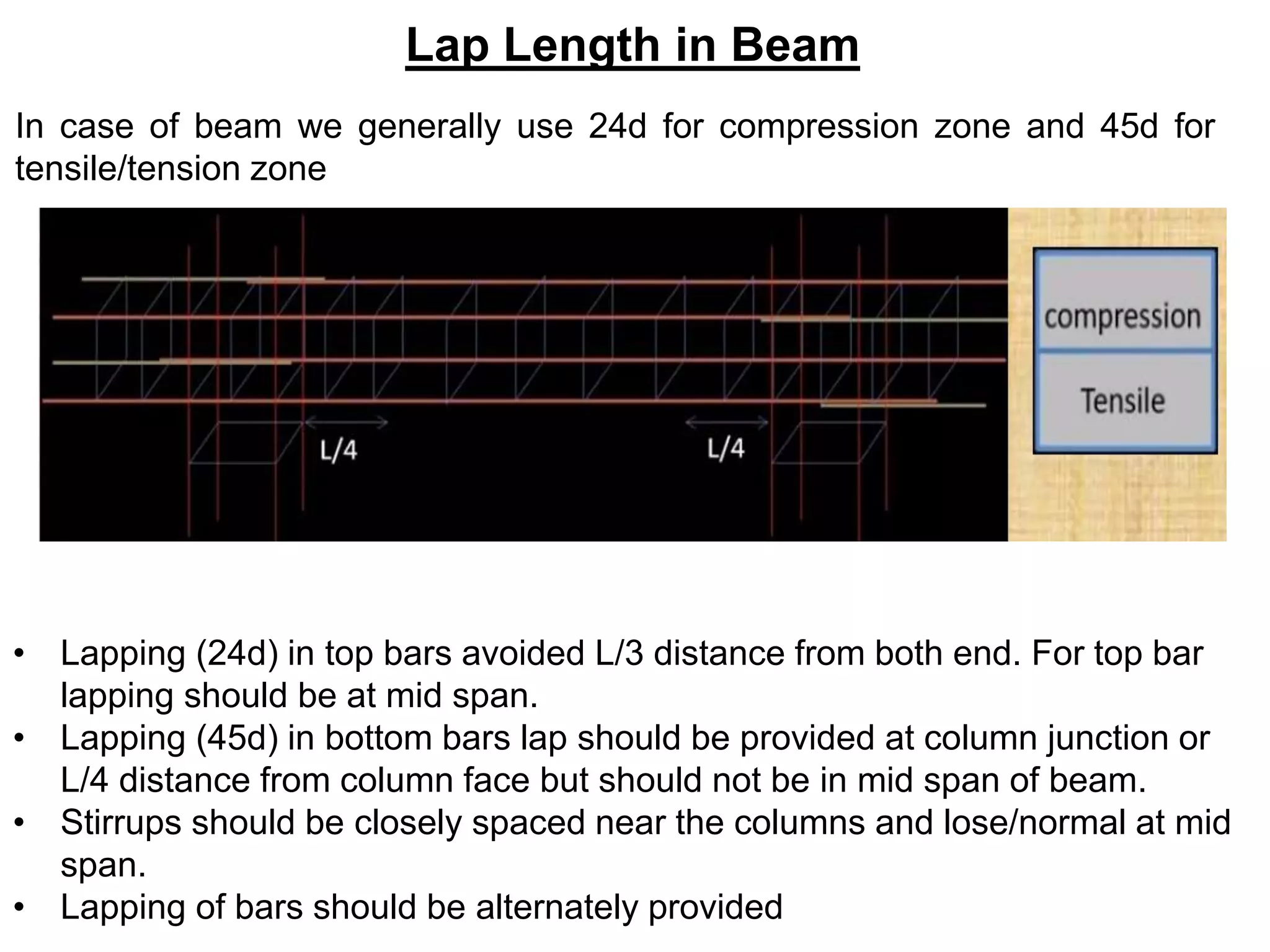
In case of beam we generally use 24d for compression zone and 45d for
tensile/tension zone
• Lapping (24d) in top bars avoided L/3 distance from both end. For top bar
lapping should be at mid span.
• Lapping (45d) in bottom bars lap should be provided at column junction or
L/4 distance from column face but should not be in mid span of beam.
• Stirrups should be closely spaced near the columns and lose/normal at mid
span.
• Lapping of bars should be alternately provided
48.
Lap position inBeam, Column and Slab
Laps:
- between bars should normally be staggered and not located in
areas of high moments