Downloaded 315 times
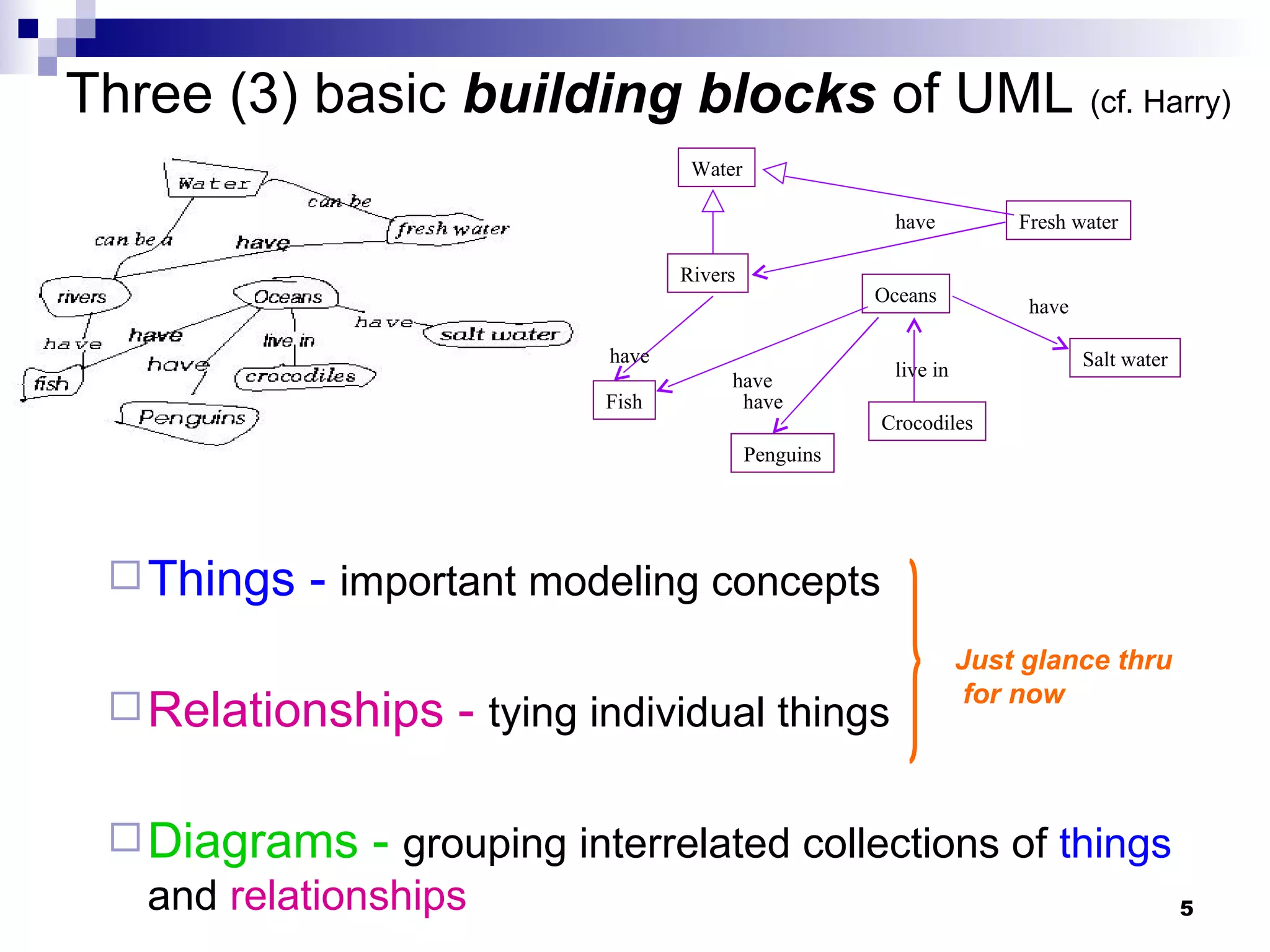
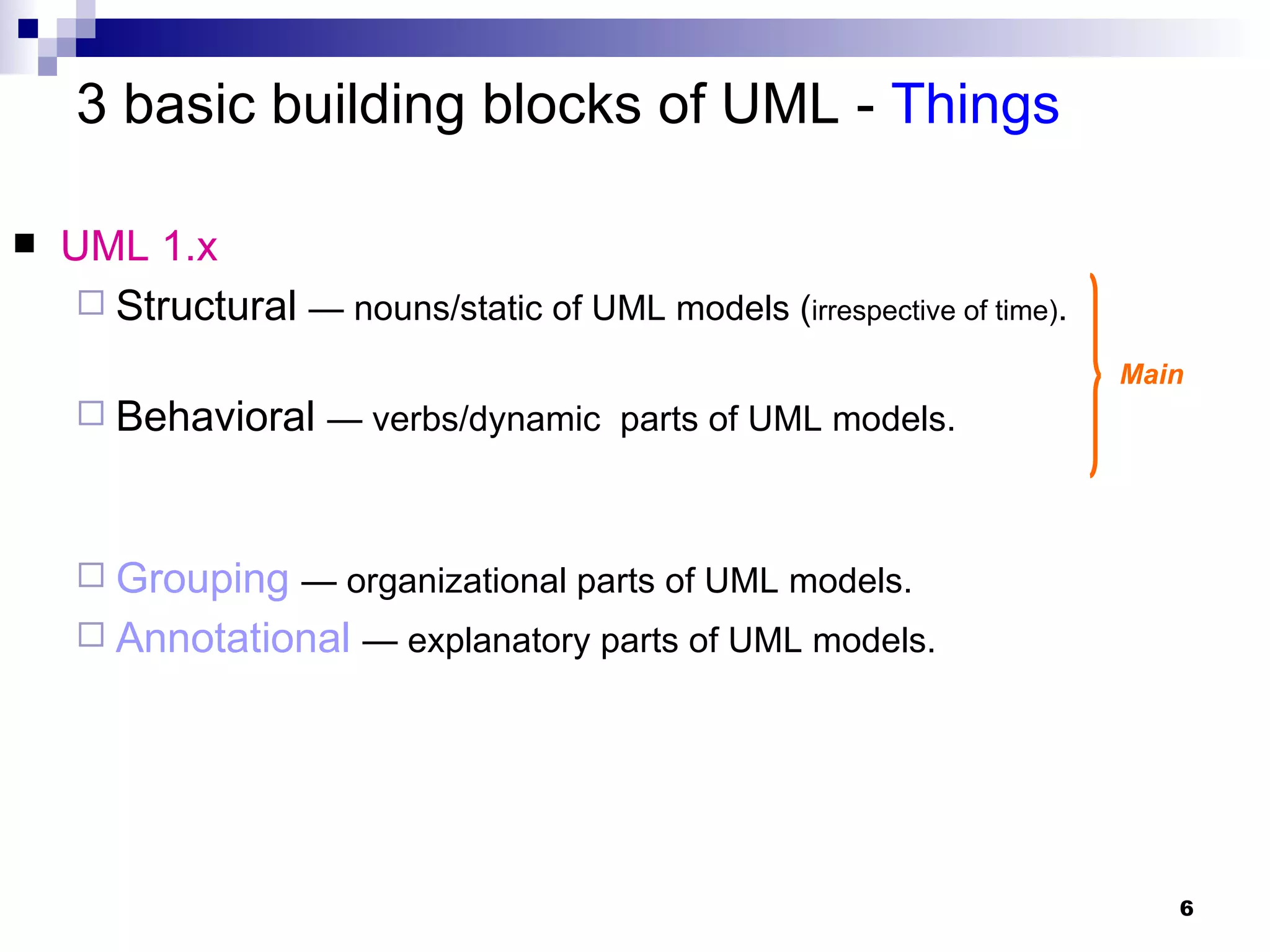
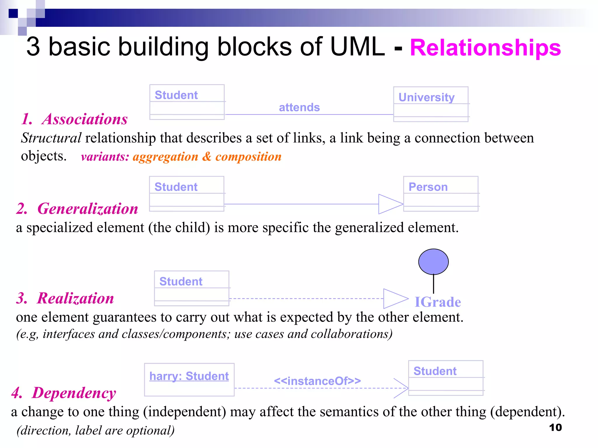
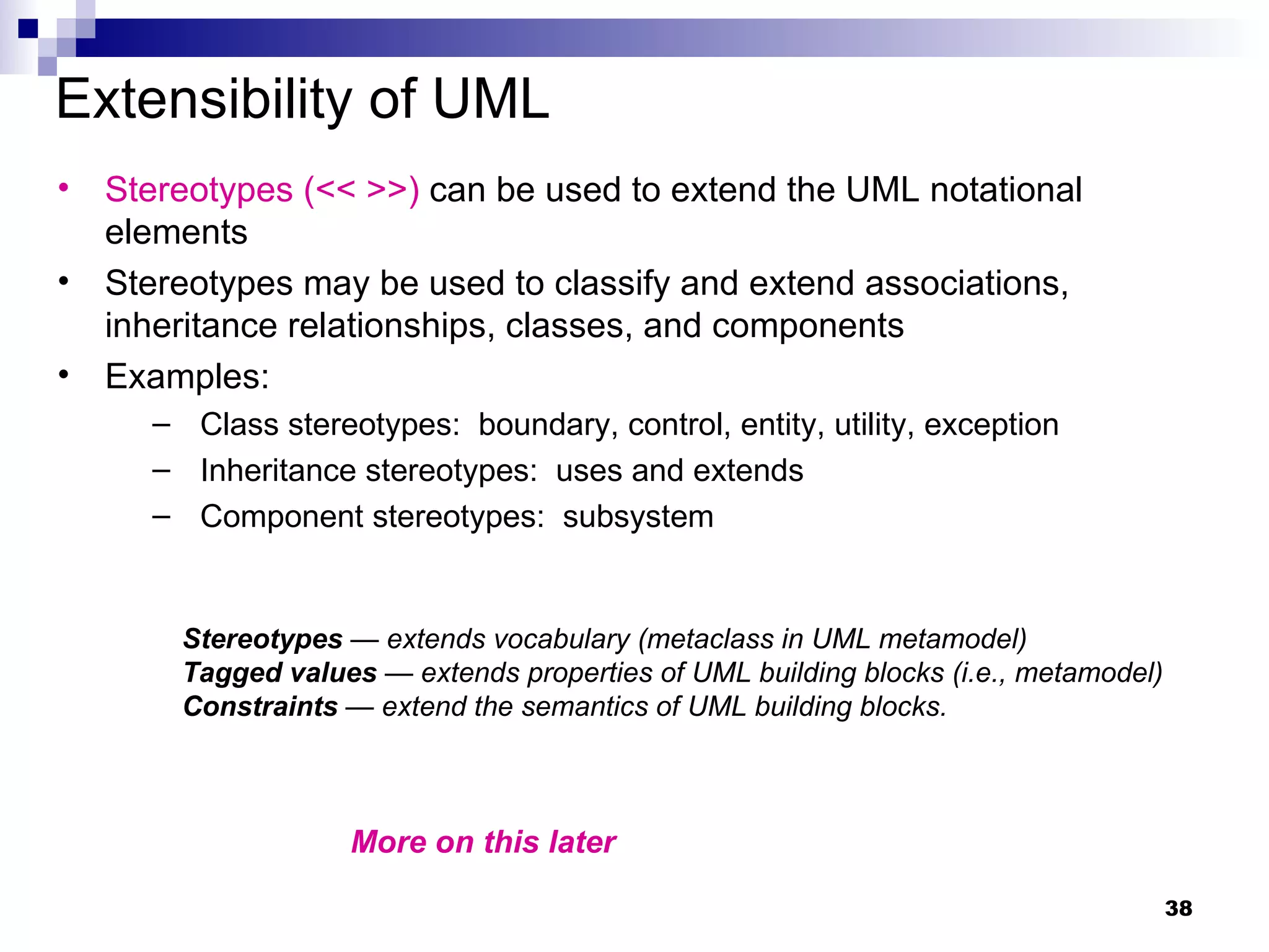
![concurrent lifelines for conditionals for concurrency linking sequence diagrams ob1:C1 ob3:C3 ob2:C2 ob3:C3 op1 [x>0] foo(x) [x<0] bar(x) do(w) do(z) recurse() [z=0] jar(z) ob3:C3 [z=0] jar(z) ob3:C3 conditional recursion Sequence Diagrams – Generic vs. Instance 2 forms of sd: Instance sd: describes a specific scenario in detail; no conditions, branches or loops. Generic sd: a use case description with alternative courses. Here, conditional or concurrency?](https://image.slidesharecdn.com/m02umloverview-1228423101012685-8/75/M02-Uml-Overview-25-2048.jpg)
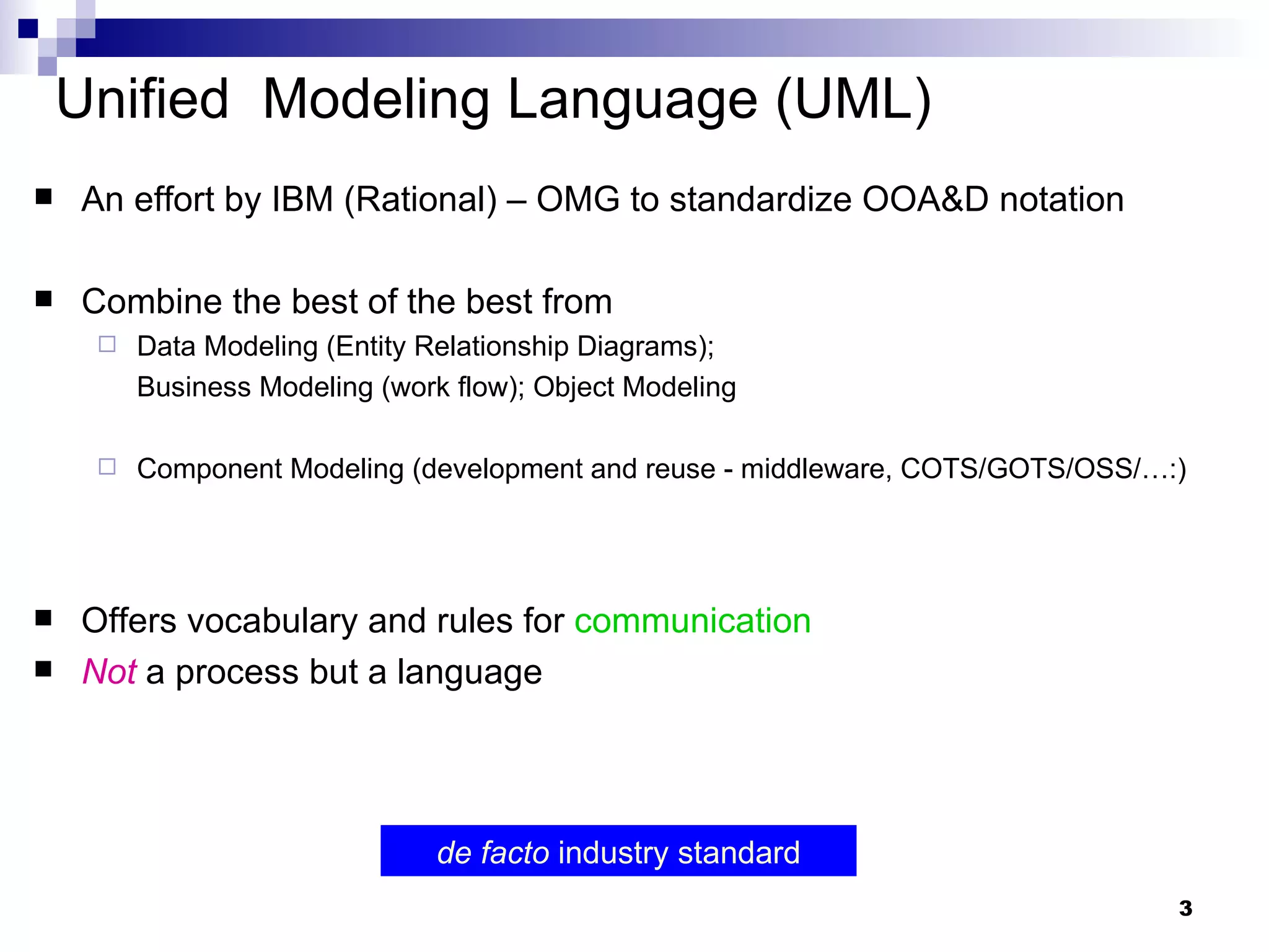
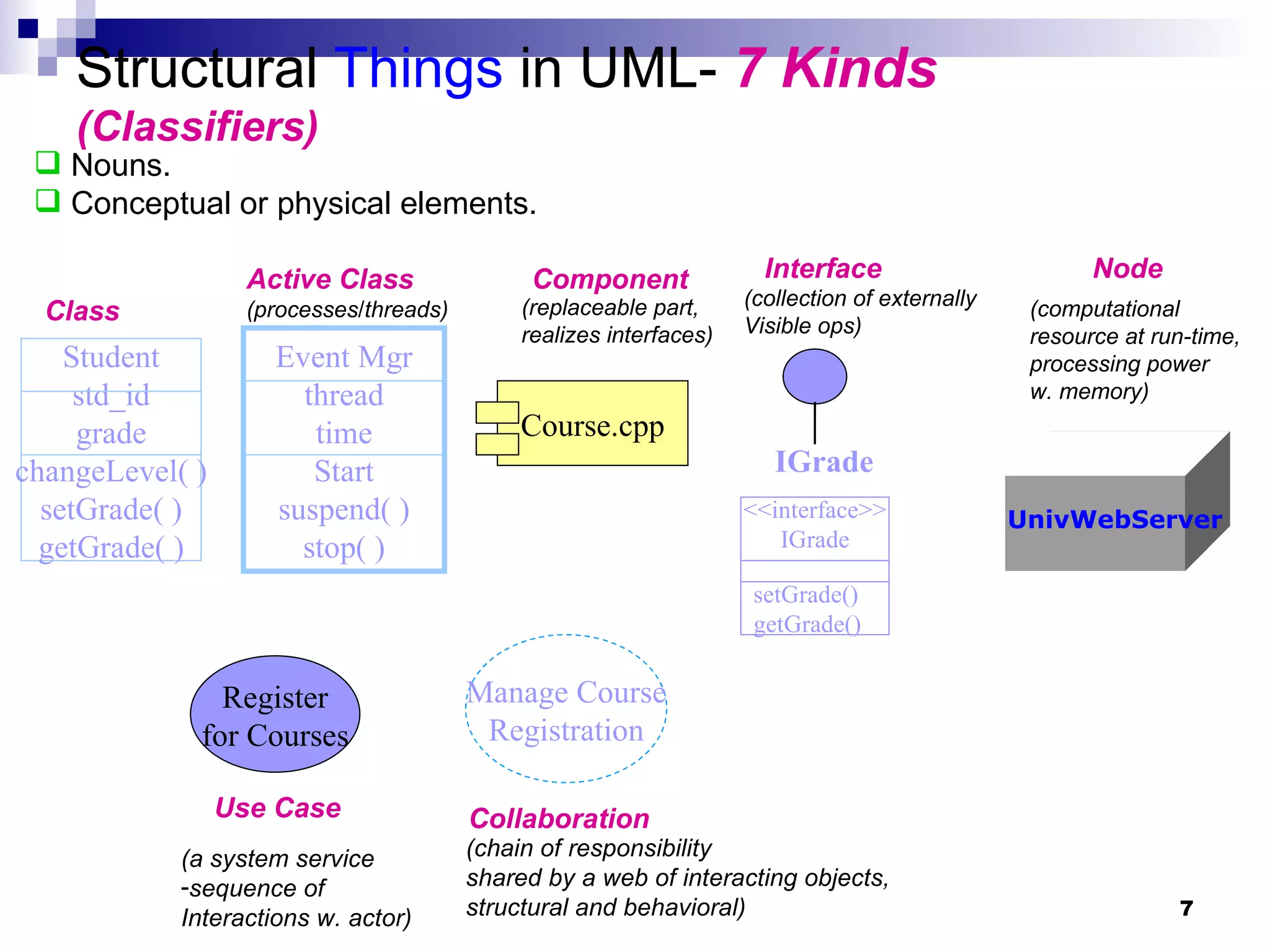
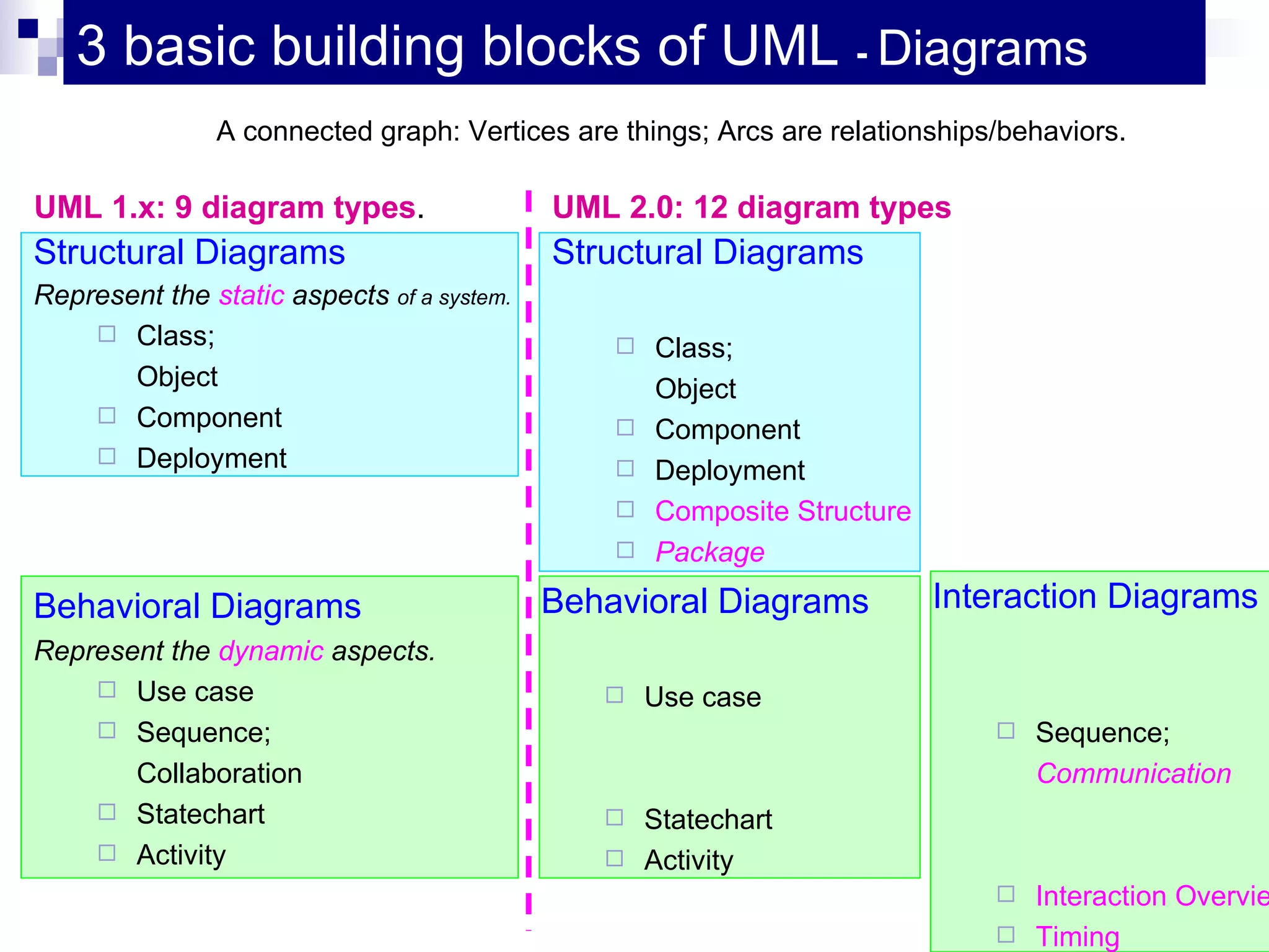
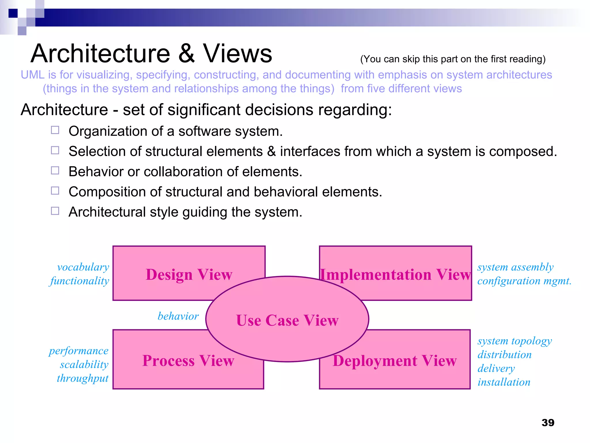
![Diagrams in UML – State Transition Diagram ( Statechart Diagram) entry: Register student exit: Increment count The life history (often of a given class: from class to object behavior) States, transitions, events that cause a transition from one state to another Actions that result from a state change What life history/class is this for? Anything wrong? … until the drop date? initial final event/action (internal) condition state State name activity Initialization Open Closed Canceled do: Initialize course do: Finalize course do: Notify registered students Add Student / Set count = 0 Add student [count < 10] [ count = 10 ] Cancel Cancel Cancel](https://image.slidesharecdn.com/m02umloverview-1228423101012685-8/75/M02-Uml-Overview-31-2048.jpg)
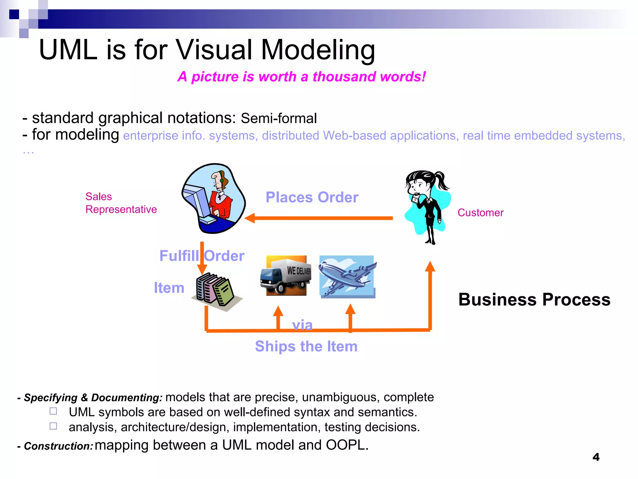
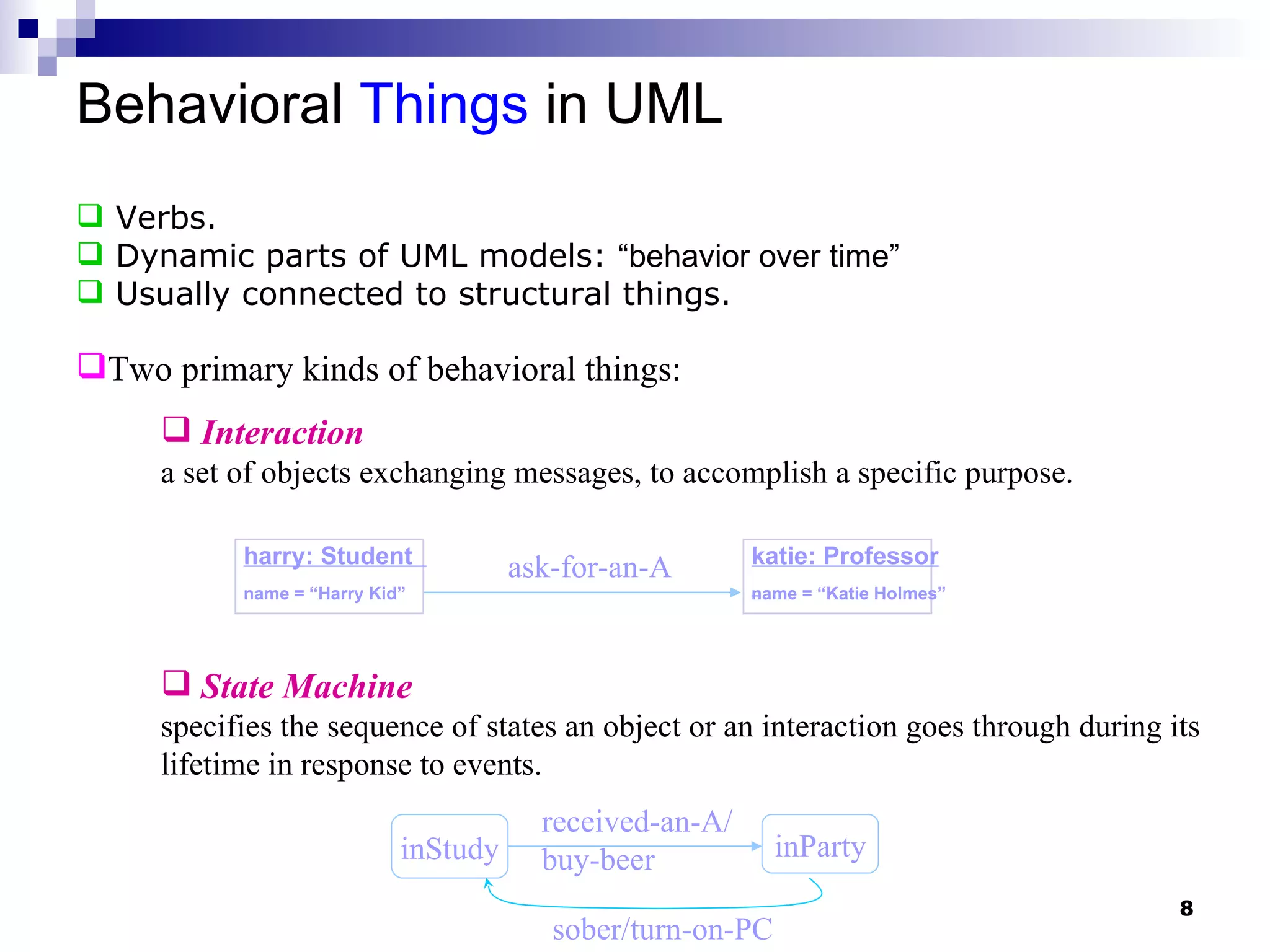
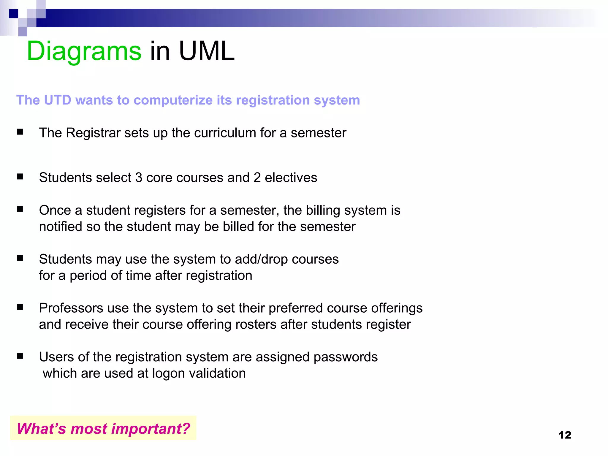
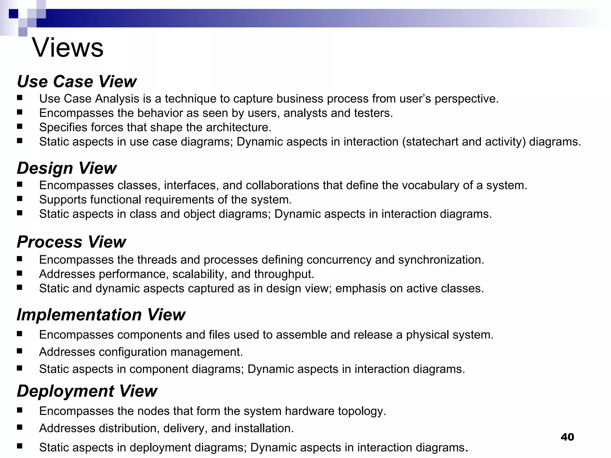
![Diagrams in UML – Activity Diagrams Synchronization Initialize course [ count < 10 ] A special kind of statechart diagram that shows the flow from activity to activity . Add student Close course [else] Notify Registrar Notify Billing fork/spawn activity guard initial final What is this for? Traceability??? Can you model this using SD? Can you model this using CD?](https://image.slidesharecdn.com/m02umloverview-1228423101012685-8/75/M02-Uml-Overview-32-2048.jpg)


The document provides an overview of Unified Modeling Language (UML) including its history, basic building blocks, and types of diagrams. It describes that UML was created in the 1990s to standardize modeling languages and combines concepts from object-oriented analysis and design. The basic building blocks of UML are things (model elements), relationships, and diagrams used to visualize models. There are several types of diagrams for structural and behavioral modeling.