Downloaded 327 times


![Example of an activity Produced Bottles [empty] New Six-Pack Fill Bottles Label Bottles Bundle Pack Bottles [labeled] Bottles [empty] Bottles [filled] Bottles [filled] [knockOff] [continue] <<precondition>> Boolean expression <<postcondition>>Boolean expression Six-Pack Production Produced Bottles:Bootles New Six-Pack:Six-Pack Six-Pack Actions Pins (input or output parameters of actions) keywords Activity input parameter Activity output parameter Declaration of activity parameters Decision node](https://image.slidesharecdn.com/omg-fundamental-certification-42422/85/Omg-Fundamental-Certification-4-50-320.jpg)


![Decision node As soon as a token is supplied over the incoming edge, the guards at the outgoing edges are evaluated . The sequence of evaluation is not defined. As son as a condition is true, the token traverses the respective outgoing edge [X>=0] [X<0]](https://image.slidesharecdn.com/omg-fundamental-certification-42422/85/Omg-Fundamental-Certification-4-71-320.jpg)
![Decision node A decision can also define a behavior (i.e. A complex calculation). Every token arriving over the incoming edge is passed to the behavior before the guard are evaluated. The result of such calculation can be accesed in the individual guards. The behavior must not have side effects (no object changes). [X>=0] [X<0] <<decisionInput>> x=sqrt(y)](https://image.slidesharecdn.com/omg-fundamental-certification-42422/85/Omg-Fundamental-Certification-4-72-320.jpg)
![MergeNode The only purpose of a merge node is to connect incoming edges and one outgoing edge . Nothing is calculated, and nothing is expected. Merge and decision can be combined . The rhombus has several incoming and several outgoing control flows . The implicit sequence is important: first the merge and then the decision . [X>=0] [X<0]](https://image.slidesharecdn.com/omg-fundamental-certification-42422/85/Omg-Fundamental-Certification-4-73-320.jpg)


![Various notations for pins Action Action Object [state] Object [state] Action Action Object type [state] Action Action An object flow without details](https://image.slidesharecdn.com/omg-fundamental-certification-42422/85/Omg-Fundamental-Certification-4-82-320.jpg)

![Labeling object nodes Action Object Type [state] Book vehicle Booking Action Object Name: Type [state] Identify Customer Booker:Customer](https://image.slidesharecdn.com/omg-fundamental-certification-42422/85/Omg-Fundamental-Certification-4-84-320.jpg)


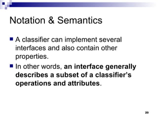
This document provides an overview of dependency relationships, interfaces, and basic behavior modeling in UML. It defines dependencies as relationships between model elements where one element requires the other. Dependency relationships can be further specified using keywords or stereotypes. Interfaces specify a subset of operations and attributes for classifiers to implement. Basic behavior in UML includes state machines, activities, interactions, and use cases, and behavior is always associated with an owning classifier or operation.