Downloaded 167 times
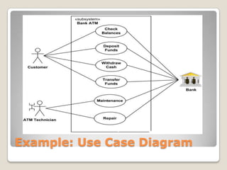
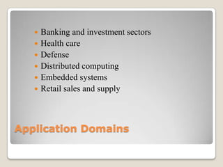
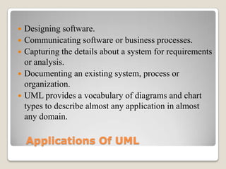
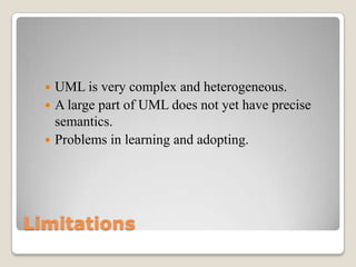


The document discusses Unified Modeling Language (UML), which is a general purpose modeling language used to specify, visualize, construct and document software systems. UML captures both the static structure and dynamic behavior of a system. It includes structural diagrams like class and component diagrams to show system architecture, and behavioral diagrams like activity and sequence diagrams to describe system functionality. UML is widely used for software design, communication, requirements analysis and documentation across various application domains.