

Recommended
More Related Content
What's hot
What's hot (20)
Similar to 3 shaft stress in shafts
Similar to 3 shaft stress in shafts (20)
More from Dr.R. SELVAM
More from Dr.R. SELVAM (20)
Recently uploaded
Recently uploaded (20)
3 shaft stress in shafts
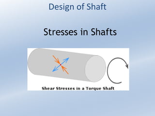
- 1. Design of Shaft Stresses in Shafts
- 2. Stresses in Shafts The following stresses are induced in the shafts : 1.Shear stresses due to the transmission of torque (i.e. due to torsional load). 2.Bending stresses (tensile or compressive) due to the forces acting upon machine elements like gears, pulleys etc. as well as due to the weight of the shaft itself. 3. Stresses due to combined torsional and bending loads.
- 3. Maximum Permissible Working Stresses for Transmission Shafts According to American Society of Mechanical Engineers (ASME) code for the design of transmission shafts, the maximum permissible working stresses in tension or compression may be taken as (a) 112 MPa for shafts without allowance for keyways. (b) 84 MPa for shafts with allowance for keyways. For shafts purchased under definite physical specifications, the permissible tensile stress (σt) may be taken as 60 percent of the elastic limit in tension (σel), but not more than 36 per cent of the ultimate tensile strength (σu). In other words, the permissible tensile stress, σt = 0.6 σel or 0.36 σu, whichever is less. The maximum permissible shear stress may be taken as (a) 56 MPa for shafts without allowance for key ways. (b) 42 MPa for shafts with allowance for keyways. For shafts purchased under definite physical specifications, the permissible shear stress (τ) may be taken as 30 per cent of the elastic limit in tension (σel) but not more than 18 percent of the ultimate tensile strength (σu). In other words, the permissible shear stress, τ = 0.3 σel or 0.18 σu, whichever is less.
- 4. Design ofShafts The shafts may be designed on the basis of 1. Strength, 2. Rigidity and 3. stiffness. In designing shafts on the basis of strength, the following cases may be considered : (a) Shafts subjected to twisting moment or torque only, (b) Shafts subjected to bending moment only, (c) Shafts subjected to combined twisting and bending moments, and (d)Shafts subjected to axial loads in addition to combined torsional and bending loads. We shall now discuss the above cases, in detail, in the following pages.
- 5. Shafts Subjected to Twisting Moment Only When the shaft is subjected to a twisting moment (or torque) only, then the diameter of the shaft may be obtained by using the torsion equation. We know that where T = Twisting moment (or torque) acting upon the shaft, J = Polar moment of inertia of the shaft about the axis of rotation, τ = Torsional shear stress, and r = Distance from neutral axis to the outer most fibre = d / 2; where d is the diameter of the shaft.
- 6. We know that for round solid shaft, polar moment of inertia, The equation (i) may now be written as From this equation, we may determine the diameter of round solid shaft ( d ). We also know that for hollow shaft, polar moment of inertia, where do and di = Outside and inside diameter of the shaft, and r = do / 2. Substituting these values in equation (i), we have...(iii) Let k = Ratio of inside diameter and outside diameter of the shaft = di / do Now the equation (iii) may be written as
- 7. From the equations (iii) or (iv), the outside and inside diameter of a hollow shaft may be determined. 1. The hollow shafts are usually used in marine work. These shafts are stronger per kg of material and they may be forged on a mandrel, thus making the material more homogeneous thanwould be possible for a solid shaft. When a hollow shaft is to be made equal in strength to a solid shaft, the twisting moment of both the shafts must be same. In other words, for the same material of both the shafts,
- 8. 2. The twisting moment (T) may be obtained by using the following relation : We know that the power transmitted (in watts) by the shaft, where T = Twisting moment in N- m, and N = Speed of the shaft in r.p.m. 3. In case of belt drives, the twisting moment ( T ) is given by T = (T1 – T2 ) R where T1 and T2 = Tensions in the tight side and slack side of the belt respectively, and R = Radius of the pulley.
- 9. Example 1 A line shaft rotating at 200 r.p.m. is to transmit 20 kW. The shaft may be assumed to be made of mild steel with an allowable shear stress of 42 MPa. Determine the diameter of the shaft, neglecting the bending moment on the shaft. Solution. Given : N = 200 r.p.m. ; P = 20 kW = 20 × 103 W; τ = 42 MPa = 42 N/mm2 Let d = Diameter of the shaft. We know that torque transmitted by the shaft, We also know that torque transmitted by the shaft ( T ),
- 10. Example 2. A solid shaft is transmitting 1 MW at 240 r.p.m. Determine the diameter of the shaft if the maximum torque transmitted exceeds the mean torque by 20%. Take the maximum allowable shear stress as 60 MPa. Solution. Given : P = 1 MW = 1 × 10⁶ W ; N = 240 r.p.m. ; Tmax = 1.2 Tmean ; τ = 60 MPa = 60 N/mm2 Let d = Diameter of the shaft. We know that mean torque transmitted by the shaft, Maximum torque transmitted, Tmax = 1.2 Tmean = 1.2 × 39 784 × 10 3= 47 741 × 103 N-mm We know that maximum torque transmitted (Tmax),