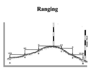
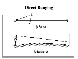
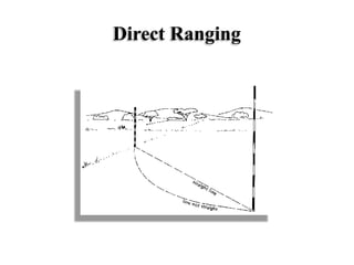
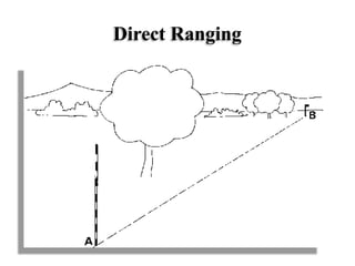
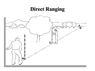
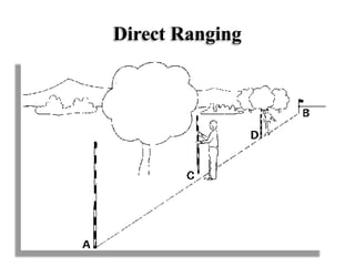
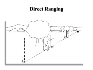
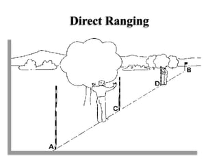
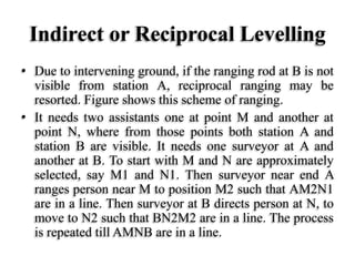
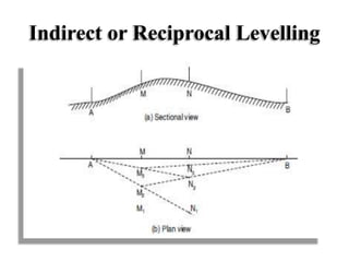
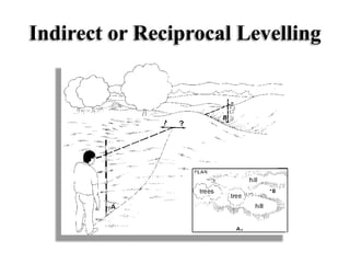
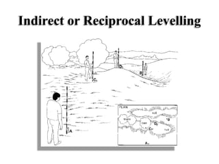
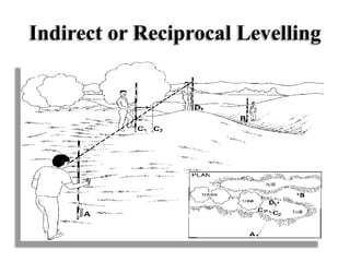
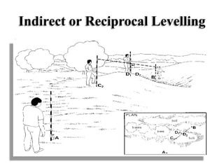
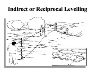
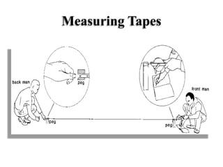
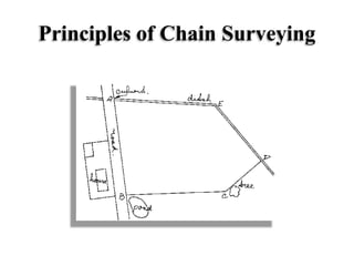
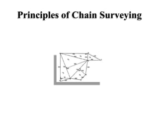
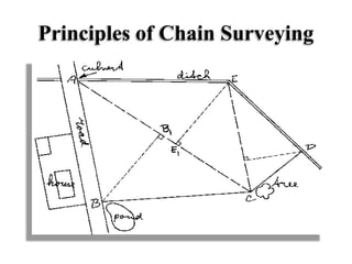
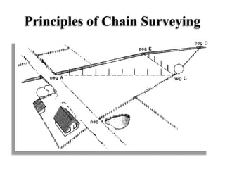
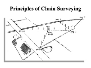
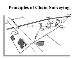
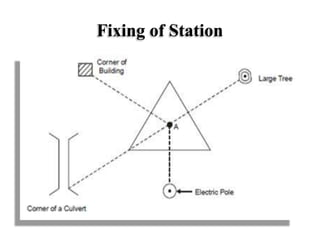
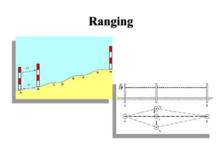
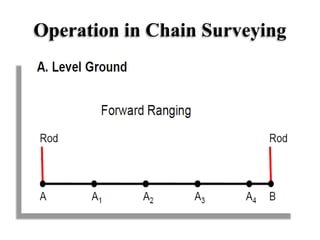
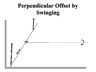
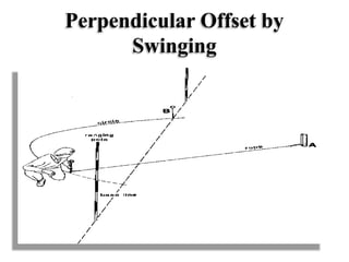
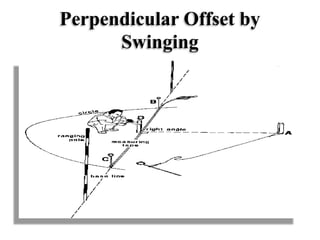
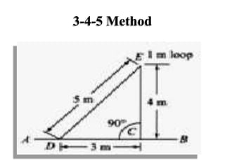
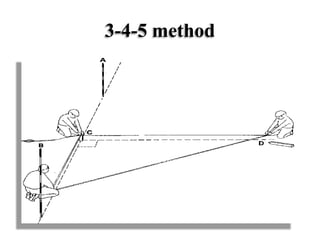
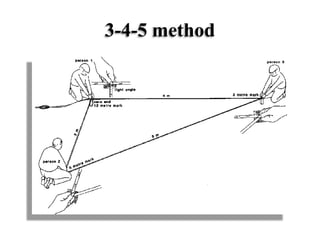
SlideShare a Scribd company logo
Ranging
• When a survey line is longer than a chain
length, it is necessary to align intermediate
points on chain line so that the measurements
are along the line. The process of locating
intermediate points on survey line is known
as ranging. There are two methods of ranging
viz., direct ranging and reciprocal ranging.
Ranging
Direct Ranging
• If the first and last points are intervisible this method is
possible.
• Stations A and B in which an intermediate point C is to
be located. Point C is selected at a distance slightly less
than a chain length. At points A and B ranging rods are
fixed. The assistant holds another ranging rod near C.
Surveyor positions himself approximately 2 m behind
station A and looking along line AB directs the assistant
to move at right angles to the line AB till he aligns the
ranging rod along AB. Then surveyor instructs the
assistant to mark that point and stretch the chain along
AC.
Direct Ranging
Direct Ranging
Direct Ranging
Direct Ranging
Direct Ranging
Direct Ranging
Direct Ranging
Direct Ranging
Indirect or Reciprocal Levelling
• Due to intervening ground, if the ranging rod at B is not
visible from station A, reciprocal ranging may be
resorted. Figure shows this scheme of ranging.
• It needs two assistants one at point M and another at
point N, where from those points both station A and
station B are visible. It needs one surveyor at A and
another at B. To start with M and N are approximately
selected, say M1 and N1. Then surveyor near end A
ranges person near M to position M2 such that AM2N1
are in a line. Then surveyor at B directs person at N, to
move to N2 such that BN2M2 are in a line. The process
is repeated till AMNB are in a line.
Indirect or Reciprocal Levelling
Linear Measurements
• The determination of the distance between two
points on the surface of the earth is one of the
basic operation of surveying. Measurement of
horizontal distances or measuring linear
measurement is required in chain surveying,
traverse surveying and other types of
surveying.
Linear Measurements
• Methods of making linear measurements
• Direct methods
• Optical methods
• E.D.M methods
Linear Measurements
• In the direct method, the distance is actually
measured during field work using a chain or a
tape. This is the most commonly used method
for linear measurements.
• In the optical methods, principles of optics are
used. The distance is not actually measured in
field but it is computed indirectly. The
instrument used for making observations is
called tacheometer.
Optical Methods
Linear Measurements
• Electronic Distance Measuring (E.D.M)
instruments have been developed quite
recently.
• These are practically replacing the
measurement of distances using chains or
tapes. There is a large variety of such
instruments and depending upon the precision
required the instruments should be used.
Electronic Distance Measuring
(E.D.M)
EDM
l l l
l
l
llP
Linear Measurements
Approximate methods
• The methods given below may be used in
reconnaissance or for detecting major mistakes in
linear measurements obtained with a chain or a
tape.
Pacing
• A distance between two points can be
approximately be determined by counting the
number of paces and multiplying it with average
length of the pace.
Pacing
Pacing
Linear Measurements
Passometer:
• It is a small instrument which counts the
number of paces.
Pedometer:
• This instrument directly gives the distance by
multiplying the number of paces with the
average pace length of the person carrying the
instrument.
Passometer
Pedometer
Pedometer
Linear Measurements
Odometer
• An odometer is a simple device which can be
attached to the wheel of a bicycle or any such
vehicle. The odometer registers the number of
revolution made by the wheel. The distance
covered is equal to the product of the number
of revolutions and the perimeter of the wheel.
Odometer
Linear Measurements
Speedometer
• This is used in automobiles for measuring
distances.
Measuring Wheel
• It is a wheel fitted with a fork and handle. The
wheel is graduated and shows a distance per
revolution. There is a dial which records the
number of revolution. Thus the distance can be
computed.
Speedometer
Measuring Wheel
Measuring Wheel
Instruments Used in Chaining
• The following instruments are used while
chaining.
• Chains
• Tapes
• Arrows
• Ranging rods and offset rods
• Laths & Whites
• Pegs
• Plumb bob
• Line Ranger
Instruments Used in Chaining
Chains
• Various types of chains used in surveying are
• Metric Chain
• Gunter’s Chain or Surveyor’s Chain
• Engineer’s Chain
• Revenue Chain
• Steel Band or band chain
Instruments Used in Chaining
Metric Chain
• Normally this chain consists of galvanized
mild steel wire of 4 mm diameter known
as link. The ends of the links are bent into
loop and connected together by means of
three oval rings which provide the
flexibility to the chain and make it less
liable to kinking. Both ends of the chain
have brass handle with swivel joint so that
the chain can be turned round without
Metric Chain
• In a metric chain at every one meter interval of
chain, a small brass ring is provided. Brass tallies
are also provided at every 5.0 m length of chain.
Each tally has different shape which indicates 5 ,
10, 15m from any one side of the chain, metric
chains are available in 20 m and 30 m length.
• A 20 m chain has 100 links each of 20 cm and 30
m chain has 150 links. Length of chain is
embossed on the brass handles of the chain.
Metric Chain
Instruments Used in Chaining
Günter's chain
• A 66 feet long chain consists of 100 links each
of 0.66 ft it is known as Gunter’s Chain
• Here, 10 sq chain are equal to 1 acre,
• 10 chains= 1 furlong and 8 furlongs = 1 mile
• This chain is suitable for taking length in miles
and areas in acres.
Günter's Chain
Günter's Chain
Instruments Used in Chaining
Engineer’s Chain
• A 100 ft chain of 100 links each of 1 foot is
known as Engineer’s chain. Brass tags are
fastened at every 10 links. This chain is used to
measure length in feet and area in square
yards.
Engineer’s Chain
Engineer’s Chain
Instruments Used in Chaining
Revenue Chain
• Revenue chain is 33 ft long chain consisting of
16 links. This chain is used for distance
measurements in feet & inches for small areas.
Revenue Chain
Instruments Used in Chaining
Steel Band or Band Chain
• Steel bands are preferred than chains because
they are more accurate, but the disadvantages
is that they get broken easily and are difficult
to repair in the field. They are 20 and 30 m
long, 12 to 16 mm wide and 0.3 to 0.6 mm
thick. They are numbered at every metre and
divided by brass studs at every 20 cm
Steel Band or Band Chain
Testing and Adjustment of Chain
• During continuous use, the length of a chain
gets altered. Its length is shortened chiefly due
to the bending of links. Its length is elongated
either due to stretching of the links and joints
and opening out of the small rings. For
accurate work it is necessary to test the chain
time to time. The chain can be thus tested by a
steel tape or by a standard chain. Sometimes, it
is convenient to have a permanent test gauge
established where the chain is tested.
Testing and Adjustment of Chain
• When the length of a chain is measured at a
pull of 8 kg at 20 0C the length of the chain
should measure 20 m ± 5 mm and 30 m ± 8
mm for 20 m and 30 m long chain shall be
accurate to within 2 mm. Following measures
are taken to adjust the length of a chain.
Testing and Adjustment of Chain
If chain is found to be too long
• It can be adjusted by;
• Closing up the joints of the rings if found to be
opened out
• Reshaping damaged rings
• Removing one or more small rings
• Adjusting the links at the end.
Testing and Adjustment of Chain
• If the chain is found to be too short
• Straightening the bent links
• Opening the joints of the rings
• Replacing one or more small circular rings by
bigger ones.
• Inserting new rings where necessary.
• Adjusting the links at the end.
Measuring Tapes
• Tapes are used for more accurate
measurement. The tapes are classified based
on the materials of which they are made of
such as:
• Cloth or linen tape
• Fibre Tape
• Metallic Tape
• Steel tape
• Invar Tape
Measuring Tapes
Measuring Tapes
Cloth or linen Tape
• Linen tapes are closely woven linen and
varnished to resist moisture. They are
generally 10 m, 20 m, 25 m and 30 m long in
length and 12 to 15 mm wide. They are
generally used for offset measurements. These
tapes are light and flexible.
Cloth or linen Tape
Measuring Tapes
• Fibre Glass Tape
• These tapes are similar to linen and plastic
coated tapes but these are made of glass fibre.
The tapes are quite flexible, strong and non-
conductive. These can be used in the vicinity
of electrical equipment. These tapes do not
stretch or shrink due to changes in temperature
or moisture. These tapes are available in length
of 20 m, 30 m and 50 m length.
Fibre Glass Tape
Measuring Tapes
• Metallic Tape
• A linen tape reinforced with brass or copper wires
to prevent stretching or twisting of fibres is called
a metallic tape. As the wires are interwoven and
tape is varnished these wires are visible to naked
eyes. This is supplied in a lather case with a
winding device. Each metre length is divided into
ten parts (decimetres) and each part is further sub-
divided into ten parts. It is commonly used for
taking offset in chain surveying.
Metallic Tape
Measuring Tapes
• Steel Tape
• The steel tape is made of steel ribbon of width
varying from 6 to 16 mm. The commonly
available length are 10 m, 15 m, 20 m, 30 m
and 50 m. It is graduated in metres,
decimetres, and centimetres. Steel tapes are
used for accurate measurement of distances.
Steel Tape
Measuring Tapes
• Invar Tape
• Invar tape are made of alloy of nickel 36 %
and steel 64 % having very low co-efficient of
thermal expansion. These are 6 mm wide and
generally available in length of 30 m, 50m,
100m. It is not affected by change of
temperature therefore, it is used when high
degree of precesion is required.
Invar Tape
Arrows
• Arrows are made of tempered steel wire of
diameter 4 mm. one end of the arrow is bent
into ring of diameter 50 mm and the other end
is pointed. Its overall length is 400 mm.
Arrows are used for counting the number of
chains while measuring a chain line. An arrow
is inserted into the ground after every chain
length measured on the ground.
Arrows
Arrows
Ranging Rods and Offset Rods
• Ranging rods are used for ranging some intermediate
points on the survey line. Ranging rods are generally 2
to 3 m in length and are painted with alternate bands of
black or white or red and white colour with length of
each equalizing 20 cm. The location of any survey
station can be known from long distances only by
means of ranging rods. If the distance is too long, a rod
of length 4.0 to 6.0 m is used and is called ranging pole.
• The offset rod is similar to ranging rod with the
exception that instead of the flag, a hook is provided at
the top for pushing and pulling the chain or the tape. It
is also used for measuring small offsets
Ranging Rods
Ranging Rods
Offset Rods
Ranging Rods and Offset Rods
Laths & Whites
Laths
• Laths are 0.5 to 1.0 m long sticks of soft wood. They
are sharpened at one end and are painted with white or
light colours. They are used as intermediate points
while ranging or while crossing depressions.
Whites
• Whites are the pieces of sharpened thick sticks cut from
the nearest place in the field. One end of the stick is
sharpened and the other end is split. White papers are
inserted in the split to improve the visibility. Whites are
also used for the same purpose as laths
Laths & Whites
Pegs
• Pegs are made of timber or steel and they are
used to mark the position of the station or
terminal points of a survey line. Wooden pegs
are 15 cm long and are driven into the ground
with the help of a hammer.
Wooden Pegs
Pegs
Plumb Bob
• Plumb-bob is used to transfer points on the
ground. It is also used for fixing the
instruments exactly over the station point
marked on the ground by checking the centre
of the instrument whether coincides with the
centre of the peg or station not, by suspending
the plumb-bob exactly at the centre of the
instrument under it. Plumb bob is thus used as
centring aid in theodolites and plane table.
Plumb Bob
Plumb Bob
Line Ranger
• It is an optical instrument used for
locating a point on a line and hence
useful for ranging. It consists of two
isosceles prisms placed one over the other
and fixed in an instrument with handle.
The diagonals of the prisms are silvered
so as to reflect the rays.
Ranging by Line Ranger
Line Ranger
• Its advantage is it needs only one person to
range. The instrument should be occasionally
tested by marking three points in a line and
standing on middle point observing the
coincidence of the ranging rods. If the images
of the two ranging rods do not appear in the
same line, one of the prism is adjusted by
operating the screw provided for it.
Line Ranger
Line Ranger
• To locate point C on line AB (ref. Fig.) the surveyor
holds the instrument in hand and stands near the
approximate position of C. If he is not exactly on line
AB, the ranging rods at A and B appear separated as
shown in Fig. (b). The surveyor moves to and fro at
right angles to the line AB till the images of ranging
rods at A and B appear in a single line as shown in
Fig. (c). It happens only when the optical square is
exactly on line AB. Thus the desired point C is
located on the line AB.
Line Ranger
Line Ranger
Chain Surveying
• Chain surveying is the type of surveying in which
only linear measurements are taken in the field.
• This type of surveying is done for surveying of
small extent to describe the boundaries of plots of
land and to locate the existing feature on them.
• It is the method of surveying in which the area is
divided into network of triangles and the sides of
the various triangles are measured directly in the
field with a chain or a tape and no angular
measurements are taken.
Principles of Chain Surveying
• The principle of chain surveying is to divide the
area into a number of triangles of suitable sides.
As a triangle is the only simple plane geometrical
figure which can be plotted from the length of the
three sides even if the angles are not known. A
network of triangles is preferred to chain
surveying.
• Triangulation is the principle of chain surveying.
If the area to be surveyed is triangle in shape and
if the lengths and sequence of its three sides are
recorded, the plan of the area can be easily drawn.
Principles of Chain Surveying
Terms related to Chain
Surveying
Survey Stations
• Survey stations are the points at the beginning
and at the end of a chain line they may also
occur at any convenient position on the chain
line. Such station may be
• Main Stations
• Subsidiary Stations
• Tie Stations
Terms related to Chain Surveying
Terms related to Chain
Surveying
• Main Station Stations along the boundary of an
area as controlling points are known as ‘Main
Stations’ The lines joining the main station are
called ‘ Main Survey Lines’. The main survey
lines should cover the whole area to be
surveyed. The main stations are denoted by Δ.
Terms related to Chain
Surveying
• Subsidiary Stations: Stations which are on
the main survey lines or any other survey lines
are known as ‘ Subsidiary Stations’ these
stations are taken to run subsidiary lines for
dividing the area into triangles, for checking
the accuracy of triangles and for locating
interior details.
Terms related to Chain
Surveying
• Tie Stations:
• These stations are also subsidiary stations
taken on the main survey lines. Lines joining
the stations are known as ‘ Tie lines’ Tie lines
are taken to locate interior details.
Terms related to Chain
Surveying
Main Survey Lines:
• The line joining the main stations are called
main survey lines or chain lines.
Terms related to Chain
Surveying
• Base Line: The line on which the framework of the
survey is built is known as ‘ Base line’. It is the most
important line of the survey. Generally the longest of
the main survey lines is considered as the base line.
This lines should be taken through fairly level ground,
and should be measured very carefully and accurately.
Terms related to Chain
Surveying
• Check Line
• The line joining the apex point of a triangle to
some fixed points on its base is known as ‘
Check line’. It is taken to check the accuracy
of the triangle. Sometimes this line helps to
locate interior details.
Terms related to Chain
Surveying
• Tie Line
• A line joining tie stations is termed as a tie
line. It is run to take the interior details which
are far away from the main lines and also to
avoids long offsets. It can also serve as check
line.
Selection of Survey Station
• The following points should be considered while
selecting survey stations:
• It should be visible from at least two or more
stations.
• As far as possible main lines should run on level
ground.
• All triangles should be well conditioned (No
angle less than 30º).
• Main network should have as few lines as
possible.
Selection of Survey Station
• Each main triangle should have at least one
check line.
• Obstacles to ranging and chaining should be
avoided.
• Sides of the larger triangles should pass as
close to boundary lines as possible.
• Trespassing and frequent crossing of the roads
should be avoided
Operation in Chain Surveying
• The following operations are involved in chain
surveying.
• Chaining
• Ranging
• Offsetting
• These three operations are done
simultaneously during chain Surveying.
Operation in Chain Surveying
Chaining
Chaining on Level Ground
• The method of taking measurement with the help
of chain or tape is termed as chaining.
Chaining involves following operations
• Fixing the stations
• Unfolding the chain
• Ranging
• Measuring the distance (Survey Line)
• Folding the Chain
Operation in Chain Surveying
Fixing of Station
• Stations are first of all marked with pegs and
ranging rods to make them visible.
Unfolding of a Chain
• To open a chain, the strap is unfastened and the
two brass handles are held in the left hand and the
bunch is thrown forward with the right hand.
Then one chainmen moves forward by holding the
other handle until the chain is completely
extended.
Fixing of Station
Unfolding of a Chain
Operation in Chain Surveying
Ranging
• The process of establishing intermediate points
on a straight line between two end points is
known as ranging. Ranging must be done
before a survey line is chained
Ranging ( Code of Signals)
Sr. No. Signal by the Surveyor Meaning of the signal to the
assistant
1 Rapid Sweep with right hand Move considerable towards left
2 Slow Sweep with right hand Move slowly towards left
3 Right arm extended Continuously move towards left
4 Right arm up and move to the right Plumb the rod towards left
5 Rapid Sweep with left hand Move considerable towards right
6 Slow Sweep with left hand Move slowly towards right
7 Left arm extended Continuously move towards right
8 Left arm up and move to the right Plumb the rod towards right
9 Both hand above head and brought
down
Ranging is correct
10 Both arm extended horizontally
and brought down quickly
Fix the ranging rod
Ranging
Operation in Chain Surveying
Measuring the distance (Survey Line)
• Two persons are required in this operation, i.e.
Leader and Follower.
• The chainman at the forward end of the chain
who drags the chain forward, is known as the
leader
• The chainmen at the rear end of the chain, who
holds the zero end of the chain at the station, is
known as the follower.
Operation in Chain Surveying
• To chain the line, the leader moves forward by dragging the
chain line and taking with him ranging rod and ten arrows.
The follower stands at the starting station by holding the
other end of the chain. When the chain is fully extended, the
leader holds the ranging rod vertically at arms length.
• The follower directs the leader to move his rod to the left or
right until the ranging rod is exactly in the line. Then the
follower holds the zero end of the chain by touching the
station peg.
• The leader stretches the chain by moving it up and down
with both hands, and finally place it on the line. He then
inserts an arrow on the ground at the end of the chain and
mark it with cross.
Operation in Chain Surveying
• Again the leader moves forward by dragging the chain
with nine arrows and the ranging rod. At the end of the
chain, he fixes another arrow as before, As the leader
moves further, the follower picks the arrow which were
inserted by the leader. During chaining the surveyor or
an assistant should conduct the ranging operation.
• In this way, chaining is continued, when all the arrows
are inserted the leader has non left with him, the
follower hands over to the leader.
• To measure the fractional length, the leader should drag
the chain beyond the station and the follower should
hold the zero end of the chain at last arrow, then odd
links should be counted.
Operation in Chain Surveying
Folding of Chain
• To fold the chain, a chainmen should move
forward by pulling the chain at the middle. Then
the two halves of the chain will come side by side.
After this, commencing from the central position
of the chain, two pairs of links are taken at a time
with the right hand and placed on the left hand
alternately in both directions. Finally the two
brass handles will appear at top. The bunch
should be then fastened by the strap.
Folding of Chain
Operation in Chain Surveying
Chaining on Sloping Ground
• The object of survey is to prepare a plan or a map.
In the plan or a map the distance plotted between
any two points is always a straight line. Even if
the chaining is done on a sloping ground, this
sloping distance is converted into horizontal
equivalent distance while plotting.
• There are two methods of finding out horizontal
distance while on a sloping ground.
• Direct Method
• Indirect Method
Operation in Chain Surveying
Direct Method
• This method is also called method of stepping in this method, the
distance is measured in small horizontal stretches. A suitable length of
chain or tape say l1 is taken. The follower holds the zero end of the
tape at a point on the top of the hill or sloping ground. i.e. at point A.
The tape is stretched horizontally from A at small length l1 of 3 to 5 m.
The point at the end of the l1 is dropped and marked on the ground as
a1. From a1, again tape is stretched exactly in a horizontal plane at a
convenient step l2 and drop end of l2 on the ground as b1. Likewise
entire length of line on the sloping ground is measured.
• Finally the total horizontal length of the line AB, i.e. D is obtained
• D= l1 + l2 + l3 + ……… ln
• Where ln= the last step for the given survey line
Operation in Chain Surveying
• Indirect Method
• Indirect method involves calculation from the
directly measured length these methods are
briefly explained here.
Method-1
• Horizontal distance of the segment is calculated
by knowing sloping length of the segment and
angle of inclination of that with horizontal.
• The angle of the sloping surface with horizontal
can be known by a simple handy instrument
called as abney’s level
Operation in Chain Surveying
• Total Distance D= ∑d = d1 +d2 +….dn, and
• d= l CosӨ for d1 = l1 Cos Ө1
Where,
Ө = angle of sloping surface with horizontal and
l= sloping length.
Operation in Chain Surveying
Clinometer
Clinometer
Abney’s level
Abney’s level
Operation in Chain Surveying
Method 2
• If elevation difference between two terminal point
and the sloping distance between the two terminal
point is known, the horizontal distance H can be
calculated as,
• H= l2 – D2
• Where,
• l= sloping length
• D= Elevation difference between two points
Operation in Chain Surveying
Method 3
• This method is also known as hypotenusal allowance
method. The chaining is done on the sloping ground,
but instead of putting the end arrow at the actual end of
the chain, it is put at some advanced distance and that
point is considered as the end of one chain length.
• In this method, the chain of 20 m length ends at point
B. Therefore, sloping length l = 20 m, but the actual
horizontal length (H) is less than 20 m and calculation
is required to calculate horizontal distance based on Ө.
Angle of inclination of ground.
Operation in Chain Surveying
• Horizontal distance H= (l + a) Cos Ө ,
Where,
H is intended to make one chain length,
• Therefore ,
• H= (l + a) Cos Ө
Here, AB= one chain length= l= H= 20 m
• Therefore Put H= l= 20 m
• 20= (20 +a) Cos Ө
• 20 Sec Ө= 20 + a
• a= 20 Sec Ө – 20
• a= 20 (Sec Ө – 1)
Operation in Chain Surveying
• Where a hypotenusal allowance for 20 m chain
• For a chain other than 20 m length,
• a= l (Sec Ө – 1) where l= length of chain in m
• Thus the arrow is inserted at (l+a) distance on
the ground instead of at the end of chain. Thus
the horizontal distance of this sloping distance
on ground is equal to one chain length.
Operation in Chain Surveying
Offsets
• Lateral measurements to chain lines for
locating ground features are known as offsets.
For this purpose
• perpendicular or oblique offsets may be taken .
If the object to be located (say road) is curved
more number of offsets should be taken. For
measuring offsets tapes are commonly used.
Offsets
Perpendicular Offsets
• The offsets which are taken perpendicular to
the chain line are termed as perpendicular
offsets. These offsets are taken by holding zero
end of the tape at the object and swinging the
tape on the chain line. The shortest distance
measured from object to the chain line is
usually the perpendicular offset.
Perpendicular Offsets
Offsets
Oblique Offset
• Oblique distance is always greater than
perpendicular distance. All the offsets which
are not taken at the right angle to chain line are
known as oblique offsets.
Oblique Offset
Offsets
Offsets
• For setting perpendicular offsets any one of the
following methods are used:
• (i) Swinging
• (ii) Using cross staffs
• (iii) Using optical or prism square.
Perpendicular Offset by
Swinging
• Chain is stretched along the survey line. An
assistant holds the end of tape on the object.
Surveyor swings the tape on chain line and
selects the point on chain where offset distance
is the least.
• and notes chain reading as well as offset
reading in a field book on a neat sketch of the
object
Perpendicular Offset by
Swinging
Perpendicular Offset by
Swinging
Perpendicular Offset by
Swinging
Perpendicular Offset by
Swinging
Perpendicular Offsets Using Cross
Staffs
• Three different types of cross staffs used for setting
perpendicular offsets. All cross staffs are having two
perpendicular lines of sights. The cross staffs are
mounted on stand. First line of sight is set along the
chain line and without disturbing setting right angle line
of sight is checked to locate the object.
• With open cross staff (Fig(a)) it is possible to set
perpendicular only, while with French cross staff
• (Fig(b)), even 45º angle can be set. Adjustable cross
staff can be used to set any angle also, since there are
graduations and upper drum can be rotated over lower
drum.
Perpendicular Offsets Using Cross
Staffs
Perpendicular Offsets Using Cross
Staffs
Perpendicular Offsets Using Optical
Square and Prism Square
• These instruments are based on the optical
principle that if two mirrors are at angle ‘θ’ to
each other,
• they reflect a ray at angle ‘2θ’. Figure shows a
typical optical square.
Perpendicular Offsets Using Optical
Square and Prism Square
Optical Square and Prism
Square
Optical Square and Prism
Square
Perpendicular Offsets Using Optical
Square and Prism Square
Perpendicular Offsets Using Optical
Square and Prism Square
Perpendicular Offsets Using Optical
Square and Prism Square
Perpendicular Offsets Using Optical
Square and Prism Square
Perpendicular Offsets Using Optical
Square and Prism Square
Perpendicular Offsets Using Optical
Square and Prism Square
3-4-5 Method
• AB is the chain line it is required to erect a
perpendicular at C of the chain line. Establish a pt
D at 3 m distance. 5m & 6m marks are brought to
gather to form a loop .The tape is stretched tight
by fastening the end D and C. The point D is
established such that DE = 5 m and CE= 4 m and
CD = 3 m and DE2 = CD2 + DE2
• i.e. 5 2 = 3 2 + 4 2 = 25 thus Angle DCE = 90 0
• i.e. CE is perpendicular to chain line at C
3-4-5 Method
3-4-5 method
3-4-5 method
Linear measurement

More Related Content

What's hot

Chain surveying.1
Chain surveying.1Chain surveying.1
Chain surveying.1
Decentumang
 
Chain surveying
Chain surveyingChain surveying
Chain surveying
JNTUK
 
traversing of survey
traversing of surveytraversing of survey
traversing of survey
Self-employed
 
Tacheometric surveying ppt
Tacheometric surveying pptTacheometric surveying ppt
Tacheometric surveying ppt
Naufil Sayyad
 
Surveying i
Surveying iSurveying i
Surveying i
Self employed
 
Surveying and levelling
Surveying and levellingSurveying and levelling
Surveying and levelling
KishanKelothu
 
Theodolite surveying
Theodolite surveying Theodolite surveying
Theodolite surveying
neharajpl
 
Avinesh surveying lab manuals
Avinesh surveying lab manualsAvinesh surveying lab manuals
Avinesh surveying lab manualsavineshgautam
 
Theodolite surveying
Theodolite surveying Theodolite surveying
Theodolite surveying
neharajpl
 
surveying and geomatics
surveying and geomaticssurveying and geomatics
surveying and geomatics
Rashmi.R.Belur Setty
 
LEVELLING METHODS AND INSTRUMENTS IN SURVEYING
LEVELLING METHODS AND INSTRUMENTS IN SURVEYINGLEVELLING METHODS AND INSTRUMENTS IN SURVEYING
LEVELLING METHODS AND INSTRUMENTS IN SURVEYING
ATHIRA B K
 
Compass survey part 1
Compass survey part 1Compass survey part 1
Compass survey part 1
ArunRavi43
 
Module-I SURVEYING-I [BTCVC304]
Module-I SURVEYING-I [BTCVC304]Module-I SURVEYING-I [BTCVC304]
Module-I SURVEYING-I [BTCVC304]
Dr. BASWESHWAR JIRWANKAR
 
Compass surveying
Compass surveyingCompass surveying
Compass surveyingAhmed Eid
 
Introduction to surveying
Introduction to surveyingIntroduction to surveying
Introduction to surveying
Mir Zafarullah
 
Levelling in Surveying
Levelling in SurveyingLevelling in Surveying
Levelling in Surveying
RAHUL SINHA
 
Plane Table Surveying PPt
Plane Table Surveying PPtPlane Table Surveying PPt
Plane Table Surveying PPt
mohit kumar panchal
 
tacheometric surveying
tacheometric surveyingtacheometric surveying
tacheometric surveying
Mujeeb Muji
 
Tacheometry ppt
Tacheometry pptTacheometry ppt
Tacheometry ppt
Vilas Nikam
 
Theodolite traversing, purpose and principles of theodolite traversing
Theodolite traversing, purpose and principles of theodolite traversingTheodolite traversing, purpose and principles of theodolite traversing
Theodolite traversing, purpose and principles of theodolite traversing
Dolat Ram
 

What's hot (20)

Chain surveying.1
Chain surveying.1Chain surveying.1
Chain surveying.1
 
Chain surveying
Chain surveyingChain surveying
Chain surveying
 
traversing of survey
traversing of surveytraversing of survey
traversing of survey
 
Tacheometric surveying ppt
Tacheometric surveying pptTacheometric surveying ppt
Tacheometric surveying ppt
 
Surveying i
Surveying iSurveying i
Surveying i
 
Surveying and levelling
Surveying and levellingSurveying and levelling
Surveying and levelling
 
Theodolite surveying
Theodolite surveying Theodolite surveying
Theodolite surveying
 
Avinesh surveying lab manuals
Avinesh surveying lab manualsAvinesh surveying lab manuals
Avinesh surveying lab manuals
 
Theodolite surveying
Theodolite surveying Theodolite surveying
Theodolite surveying
 
surveying and geomatics
surveying and geomaticssurveying and geomatics
surveying and geomatics
 
LEVELLING METHODS AND INSTRUMENTS IN SURVEYING
LEVELLING METHODS AND INSTRUMENTS IN SURVEYINGLEVELLING METHODS AND INSTRUMENTS IN SURVEYING
LEVELLING METHODS AND INSTRUMENTS IN SURVEYING
 
Compass survey part 1
Compass survey part 1Compass survey part 1
Compass survey part 1
 
Module-I SURVEYING-I [BTCVC304]
Module-I SURVEYING-I [BTCVC304]Module-I SURVEYING-I [BTCVC304]
Module-I SURVEYING-I [BTCVC304]
 
Compass surveying
Compass surveyingCompass surveying
Compass surveying
 
Introduction to surveying
Introduction to surveyingIntroduction to surveying
Introduction to surveying
 
Levelling in Surveying
Levelling in SurveyingLevelling in Surveying
Levelling in Surveying
 
Plane Table Surveying PPt
Plane Table Surveying PPtPlane Table Surveying PPt
Plane Table Surveying PPt
 
tacheometric surveying
tacheometric surveyingtacheometric surveying
tacheometric surveying
 
Tacheometry ppt
Tacheometry pptTacheometry ppt
Tacheometry ppt
 
Theodolite traversing, purpose and principles of theodolite traversing
Theodolite traversing, purpose and principles of theodolite traversingTheodolite traversing, purpose and principles of theodolite traversing
Theodolite traversing, purpose and principles of theodolite traversing
 

Similar to Linear measurement

Linear measurement
Linear measurementLinear measurement
Linear measurement
KHUSHBU SHAH
 
Linear Measurements
Linear MeasurementsLinear Measurements
Linear Measurements
GAURAV. H .TANDON
 
2.2 linear measurement
2.2 linear measurement2.2 linear measurement
2.2 linear measurement
Digvijaysinh Gohil
 
Instruments used in surveying
Instruments used in surveyingInstruments used in surveying
Instruments used in surveying
Mir Zafarullah
 
Introduction on instruments used for chaining
Introduction on instruments used for chainingIntroduction on instruments used for chaining
Introduction on instruments used for chaining
Mujeeb Muji
 
2-Linear-Measurements.pptx
2-Linear-Measurements.pptx2-Linear-Measurements.pptx
2-Linear-Measurements.pptx
ojjeswigautam
 
Surveying and levelling
Surveying and levellingSurveying and levelling
Surveying and levelling
Parimal Jha
 
Linear measurement
Linear measurement Linear measurement
Linear measurement
RAMPRASAD KUMAWAT
 
Surveying instruments with their uses
Surveying instruments with their uses Surveying instruments with their uses
Surveying instruments with their uses
Talha Hussain
 
Basic Civil and Mechanical Engineering
Basic Civil and Mechanical EngineeringBasic Civil and Mechanical Engineering
Basic Civil and Mechanical Engineering
PAAVAI ENGINEERING COLLEGE
 
Surveying and scale_Surveying, Civil Engineering
Surveying and scale_Surveying, Civil EngineeringSurveying and scale_Surveying, Civil Engineering
Surveying and scale_Surveying, Civil Engineering
A Makwana
 
Chain surveying and offset
Chain surveying and offsetChain surveying and offset
Chain surveying and offset
Mir Zafarullah
 
Diploma(civil) sem i boce_unit 2_ elementary surveying a
Diploma(civil) sem i boce_unit 2_ elementary surveying aDiploma(civil) sem i boce_unit 2_ elementary surveying a
Diploma(civil) sem i boce_unit 2_ elementary surveying a
Rai University
 
Diploma(civil) sem i boce_unit 2_ elementary surveying a
Diploma(civil) sem i boce_unit 2_ elementary surveying aDiploma(civil) sem i boce_unit 2_ elementary surveying a
Diploma(civil) sem i boce_unit 2_ elementary surveying a
Rai University
 
Screw thread measurement
Screw thread measurementScrew thread measurement
Screw thread measurement
Chintan Mehta
 
DEFINITIONS, PRINCIPLES AND CHAIN SURVEYING
DEFINITIONS, PRINCIPLES AND CHAIN SURVEYINGDEFINITIONS, PRINCIPLES AND CHAIN SURVEYING
DEFINITIONS, PRINCIPLES AND CHAIN SURVEYING
Kamal B
 
Surveying ch-two
Surveying ch-twoSurveying ch-two
Surveying ch-two
Zewdu Minwuye Dessie
 
chain.pptx
chain.pptxchain.pptx
chain.pptx
AshishJadhav655553
 
Surveying - II
Surveying - IISurveying - II
Surveying - II
Openmaps
 

Similar to Linear measurement (20)

Linear measurement
Linear measurementLinear measurement
Linear measurement
 
Linear Measurements
Linear MeasurementsLinear Measurements
Linear Measurements
 
2.2 linear measurement
2.2 linear measurement2.2 linear measurement
2.2 linear measurement
 
Instruments used in surveying
Instruments used in surveyingInstruments used in surveying
Instruments used in surveying
 
Introduction on instruments used for chaining
Introduction on instruments used for chainingIntroduction on instruments used for chaining
Introduction on instruments used for chaining
 
2-Linear-Measurements.pptx
2-Linear-Measurements.pptx2-Linear-Measurements.pptx
2-Linear-Measurements.pptx
 
Surveying and levelling
Surveying and levellingSurveying and levelling
Surveying and levelling
 
Linear measurement
Linear measurement Linear measurement
Linear measurement
 
Surveying instruments with their uses
Surveying instruments with their uses Surveying instruments with their uses
Surveying instruments with their uses
 
Basic Civil and Mechanical Engineering
Basic Civil and Mechanical EngineeringBasic Civil and Mechanical Engineering
Basic Civil and Mechanical Engineering
 
Surveying and scale_Surveying, Civil Engineering
Surveying and scale_Surveying, Civil EngineeringSurveying and scale_Surveying, Civil Engineering
Surveying and scale_Surveying, Civil Engineering
 
Chain surveying and offset
Chain surveying and offsetChain surveying and offset
Chain surveying and offset
 
Diploma(civil) sem i boce_unit 2_ elementary surveying a
Diploma(civil) sem i boce_unit 2_ elementary surveying aDiploma(civil) sem i boce_unit 2_ elementary surveying a
Diploma(civil) sem i boce_unit 2_ elementary surveying a
 
Diploma(civil) sem i boce_unit 2_ elementary surveying a
Diploma(civil) sem i boce_unit 2_ elementary surveying aDiploma(civil) sem i boce_unit 2_ elementary surveying a
Diploma(civil) sem i boce_unit 2_ elementary surveying a
 
Screw thread measurement
Screw thread measurementScrew thread measurement
Screw thread measurement
 
DEFINITIONS, PRINCIPLES AND CHAIN SURVEYING
DEFINITIONS, PRINCIPLES AND CHAIN SURVEYINGDEFINITIONS, PRINCIPLES AND CHAIN SURVEYING
DEFINITIONS, PRINCIPLES AND CHAIN SURVEYING
 
Surveying ch-two
Surveying ch-twoSurveying ch-two
Surveying ch-two
 
L-031.pdf
L-031.pdfL-031.pdf
L-031.pdf
 
chain.pptx
chain.pptxchain.pptx
chain.pptx
 
Surveying - II
Surveying - IISurveying - II
Surveying - II
 

Recently uploaded

Cosmetic shop management system project report.pdf
Cosmetic shop management system project report.pdfCosmetic shop management system project report.pdf
Cosmetic shop management system project report.pdf
Kamal Acharya
 
Top 10 Oil and Gas Projects in Saudi Arabia 2024.pdf
Top 10 Oil and Gas Projects in Saudi Arabia 2024.pdfTop 10 Oil and Gas Projects in Saudi Arabia 2024.pdf
Top 10 Oil and Gas Projects in Saudi Arabia 2024.pdf
Teleport Manpower Consultant
 
Halogenation process of chemical process industries
Halogenation process of chemical process industriesHalogenation process of chemical process industries
Halogenation process of chemical process industries
MuhammadTufail242431
 
DESIGN A COTTON SEED SEPARATION MACHINE.docx
DESIGN A COTTON SEED SEPARATION MACHINE.docxDESIGN A COTTON SEED SEPARATION MACHINE.docx
DESIGN A COTTON SEED SEPARATION MACHINE.docx
FluxPrime1
 
TECHNICAL TRAINING MANUAL GENERAL FAMILIARIZATION COURSE
TECHNICAL TRAINING MANUAL   GENERAL FAMILIARIZATION COURSETECHNICAL TRAINING MANUAL   GENERAL FAMILIARIZATION COURSE
TECHNICAL TRAINING MANUAL GENERAL FAMILIARIZATION COURSE
DuvanRamosGarzon1
 
power quality voltage fluctuation UNIT - I.pptx
power quality voltage fluctuation UNIT - I.pptxpower quality voltage fluctuation UNIT - I.pptx
power quality voltage fluctuation UNIT - I.pptx
ViniHema
 
CME397 Surface Engineering- Professional Elective
CME397 Surface Engineering- Professional ElectiveCME397 Surface Engineering- Professional Elective
CME397 Surface Engineering- Professional Elective
karthi keyan
 
H.Seo, ICLR 2024, MLILAB, KAIST AI.pdf
H.Seo,  ICLR 2024, MLILAB,  KAIST AI.pdfH.Seo,  ICLR 2024, MLILAB,  KAIST AI.pdf
H.Seo, ICLR 2024, MLILAB, KAIST AI.pdf
MLILAB
 
Architectural Portfolio Sean Lockwood
Architectural Portfolio Sean LockwoodArchitectural Portfolio Sean Lockwood
Architectural Portfolio Sean Lockwood
seandesed
 
一比一原版(SFU毕业证)西蒙菲莎大学毕业证成绩单如何办理
一比一原版(SFU毕业证)西蒙菲莎大学毕业证成绩单如何办理一比一原版(SFU毕业证)西蒙菲莎大学毕业证成绩单如何办理
一比一原版(SFU毕业证)西蒙菲莎大学毕业证成绩单如何办理
bakpo1
 
Hybrid optimization of pumped hydro system and solar- Engr. Abdul-Azeez.pdf
Hybrid optimization of pumped hydro system and solar- Engr. Abdul-Azeez.pdfHybrid optimization of pumped hydro system and solar- Engr. Abdul-Azeez.pdf
Hybrid optimization of pumped hydro system and solar- Engr. Abdul-Azeez.pdf
fxintegritypublishin
 
在线办理(ANU毕业证书)澳洲国立大学毕业证录取通知书一模一样
在线办理(ANU毕业证书)澳洲国立大学毕业证录取通知书一模一样在线办理(ANU毕业证书)澳洲国立大学毕业证录取通知书一模一样
在线办理(ANU毕业证书)澳洲国立大学毕业证录取通知书一模一样
obonagu
 
Automobile Management System Project Report.pdf
Automobile Management System Project Report.pdfAutomobile Management System Project Report.pdf
Automobile Management System Project Report.pdf
Kamal Acharya
 
Standard Reomte Control Interface - Neometrix
Standard Reomte Control Interface - NeometrixStandard Reomte Control Interface - Neometrix
Standard Reomte Control Interface - Neometrix
Neometrix_Engineering_Pvt_Ltd
 
HYDROPOWER - Hydroelectric power generation
HYDROPOWER - Hydroelectric power generationHYDROPOWER - Hydroelectric power generation
HYDROPOWER - Hydroelectric power generation
Robbie Edward Sayers
 
block diagram and signal flow graph representation
block diagram and signal flow graph representationblock diagram and signal flow graph representation
block diagram and signal flow graph representation
Divya Somashekar
 
Water Industry Process Automation and Control Monthly - May 2024.pdf
Water Industry Process Automation and Control Monthly - May 2024.pdfWater Industry Process Automation and Control Monthly - May 2024.pdf
Water Industry Process Automation and Control Monthly - May 2024.pdf
Water Industry Process Automation & Control
 
Gen AI Study Jams _ For the GDSC Leads in India.pdf
Gen AI Study Jams _ For the GDSC Leads in India.pdfGen AI Study Jams _ For the GDSC Leads in India.pdf
Gen AI Study Jams _ For the GDSC Leads in India.pdf
gdsczhcet
 
J.Yang, ICLR 2024, MLILAB, KAIST AI.pdf
J.Yang,  ICLR 2024, MLILAB, KAIST AI.pdfJ.Yang,  ICLR 2024, MLILAB, KAIST AI.pdf
J.Yang, ICLR 2024, MLILAB, KAIST AI.pdf
MLILAB
 
CFD Simulation of By-pass Flow in a HRSG module by R&R Consult.pptx
CFD Simulation of By-pass Flow in a HRSG module by R&R Consult.pptxCFD Simulation of By-pass Flow in a HRSG module by R&R Consult.pptx
CFD Simulation of By-pass Flow in a HRSG module by R&R Consult.pptx
R&R Consult
 

Recently uploaded (20)

Cosmetic shop management system project report.pdf
Cosmetic shop management system project report.pdfCosmetic shop management system project report.pdf
Cosmetic shop management system project report.pdf
 
Top 10 Oil and Gas Projects in Saudi Arabia 2024.pdf
Top 10 Oil and Gas Projects in Saudi Arabia 2024.pdfTop 10 Oil and Gas Projects in Saudi Arabia 2024.pdf
Top 10 Oil and Gas Projects in Saudi Arabia 2024.pdf
 
Halogenation process of chemical process industries
Halogenation process of chemical process industriesHalogenation process of chemical process industries
Halogenation process of chemical process industries
 
DESIGN A COTTON SEED SEPARATION MACHINE.docx
DESIGN A COTTON SEED SEPARATION MACHINE.docxDESIGN A COTTON SEED SEPARATION MACHINE.docx
DESIGN A COTTON SEED SEPARATION MACHINE.docx
 
TECHNICAL TRAINING MANUAL GENERAL FAMILIARIZATION COURSE
TECHNICAL TRAINING MANUAL   GENERAL FAMILIARIZATION COURSETECHNICAL TRAINING MANUAL   GENERAL FAMILIARIZATION COURSE
TECHNICAL TRAINING MANUAL GENERAL FAMILIARIZATION COURSE
 
power quality voltage fluctuation UNIT - I.pptx
power quality voltage fluctuation UNIT - I.pptxpower quality voltage fluctuation UNIT - I.pptx
power quality voltage fluctuation UNIT - I.pptx
 
CME397 Surface Engineering- Professional Elective
CME397 Surface Engineering- Professional ElectiveCME397 Surface Engineering- Professional Elective
CME397 Surface Engineering- Professional Elective
 
H.Seo, ICLR 2024, MLILAB, KAIST AI.pdf
H.Seo,  ICLR 2024, MLILAB,  KAIST AI.pdfH.Seo,  ICLR 2024, MLILAB,  KAIST AI.pdf
H.Seo, ICLR 2024, MLILAB, KAIST AI.pdf
 
Architectural Portfolio Sean Lockwood
Architectural Portfolio Sean LockwoodArchitectural Portfolio Sean Lockwood
Architectural Portfolio Sean Lockwood
 
一比一原版(SFU毕业证)西蒙菲莎大学毕业证成绩单如何办理
一比一原版(SFU毕业证)西蒙菲莎大学毕业证成绩单如何办理一比一原版(SFU毕业证)西蒙菲莎大学毕业证成绩单如何办理
一比一原版(SFU毕业证)西蒙菲莎大学毕业证成绩单如何办理
 
Hybrid optimization of pumped hydro system and solar- Engr. Abdul-Azeez.pdf
Hybrid optimization of pumped hydro system and solar- Engr. Abdul-Azeez.pdfHybrid optimization of pumped hydro system and solar- Engr. Abdul-Azeez.pdf
Hybrid optimization of pumped hydro system and solar- Engr. Abdul-Azeez.pdf
 
在线办理(ANU毕业证书)澳洲国立大学毕业证录取通知书一模一样
在线办理(ANU毕业证书)澳洲国立大学毕业证录取通知书一模一样在线办理(ANU毕业证书)澳洲国立大学毕业证录取通知书一模一样
在线办理(ANU毕业证书)澳洲国立大学毕业证录取通知书一模一样
 
Automobile Management System Project Report.pdf
Automobile Management System Project Report.pdfAutomobile Management System Project Report.pdf
Automobile Management System Project Report.pdf
 
Standard Reomte Control Interface - Neometrix
Standard Reomte Control Interface - NeometrixStandard Reomte Control Interface - Neometrix
Standard Reomte Control Interface - Neometrix
 
HYDROPOWER - Hydroelectric power generation
HYDROPOWER - Hydroelectric power generationHYDROPOWER - Hydroelectric power generation
HYDROPOWER - Hydroelectric power generation
 
block diagram and signal flow graph representation
block diagram and signal flow graph representationblock diagram and signal flow graph representation
block diagram and signal flow graph representation
 
Water Industry Process Automation and Control Monthly - May 2024.pdf
Water Industry Process Automation and Control Monthly - May 2024.pdfWater Industry Process Automation and Control Monthly - May 2024.pdf
Water Industry Process Automation and Control Monthly - May 2024.pdf
 
Gen AI Study Jams _ For the GDSC Leads in India.pdf
Gen AI Study Jams _ For the GDSC Leads in India.pdfGen AI Study Jams _ For the GDSC Leads in India.pdf
Gen AI Study Jams _ For the GDSC Leads in India.pdf
 
J.Yang, ICLR 2024, MLILAB, KAIST AI.pdf
J.Yang,  ICLR 2024, MLILAB, KAIST AI.pdfJ.Yang,  ICLR 2024, MLILAB, KAIST AI.pdf
J.Yang, ICLR 2024, MLILAB, KAIST AI.pdf
 
CFD Simulation of By-pass Flow in a HRSG module by R&R Consult.pptx
CFD Simulation of By-pass Flow in a HRSG module by R&R Consult.pptxCFD Simulation of By-pass Flow in a HRSG module by R&R Consult.pptx
CFD Simulation of By-pass Flow in a HRSG module by R&R Consult.pptx
 

Linear measurement

  • 1.
  • 2. Ranging • When a survey line is longer than a chain length, it is necessary to align intermediate points on chain line so that the measurements are along the line. The process of locating intermediate points on survey line is known as ranging. There are two methods of ranging viz., direct ranging and reciprocal ranging.
  • 4. Direct Ranging • If the first and last points are intervisible this method is possible. • Stations A and B in which an intermediate point C is to be located. Point C is selected at a distance slightly less than a chain length. At points A and B ranging rods are fixed. The assistant holds another ranging rod near C. Surveyor positions himself approximately 2 m behind station A and looking along line AB directs the assistant to move at right angles to the line AB till he aligns the ranging rod along AB. Then surveyor instructs the assistant to mark that point and stretch the chain along AC.
  • 13. Indirect or Reciprocal Levelling • Due to intervening ground, if the ranging rod at B is not visible from station A, reciprocal ranging may be resorted. Figure shows this scheme of ranging. • It needs two assistants one at point M and another at point N, where from those points both station A and station B are visible. It needs one surveyor at A and another at B. To start with M and N are approximately selected, say M1 and N1. Then surveyor near end A ranges person near M to position M2 such that AM2N1 are in a line. Then surveyor at B directs person at N, to move to N2 such that BN2M2 are in a line. The process is repeated till AMNB are in a line.
  • 20. Linear Measurements • The determination of the distance between two points on the surface of the earth is one of the basic operation of surveying. Measurement of horizontal distances or measuring linear measurement is required in chain surveying, traverse surveying and other types of surveying.
  • 21. Linear Measurements • Methods of making linear measurements • Direct methods • Optical methods • E.D.M methods
  • 22. Linear Measurements • In the direct method, the distance is actually measured during field work using a chain or a tape. This is the most commonly used method for linear measurements. • In the optical methods, principles of optics are used. The distance is not actually measured in field but it is computed indirectly. The instrument used for making observations is called tacheometer.
  • 24. Linear Measurements • Electronic Distance Measuring (E.D.M) instruments have been developed quite recently. • These are practically replacing the measurement of distances using chains or tapes. There is a large variety of such instruments and depending upon the precision required the instruments should be used.
  • 26. Linear Measurements Approximate methods • The methods given below may be used in reconnaissance or for detecting major mistakes in linear measurements obtained with a chain or a tape. Pacing • A distance between two points can be approximately be determined by counting the number of paces and multiplying it with average length of the pace.
  • 29. Linear Measurements Passometer: • It is a small instrument which counts the number of paces. Pedometer: • This instrument directly gives the distance by multiplying the number of paces with the average pace length of the person carrying the instrument.
  • 33. Linear Measurements Odometer • An odometer is a simple device which can be attached to the wheel of a bicycle or any such vehicle. The odometer registers the number of revolution made by the wheel. The distance covered is equal to the product of the number of revolutions and the perimeter of the wheel.
  • 35. Linear Measurements Speedometer • This is used in automobiles for measuring distances. Measuring Wheel • It is a wheel fitted with a fork and handle. The wheel is graduated and shows a distance per revolution. There is a dial which records the number of revolution. Thus the distance can be computed.
  • 39. Instruments Used in Chaining • The following instruments are used while chaining. • Chains • Tapes • Arrows • Ranging rods and offset rods • Laths & Whites • Pegs • Plumb bob • Line Ranger
  • 40. Instruments Used in Chaining Chains • Various types of chains used in surveying are • Metric Chain • Gunter’s Chain or Surveyor’s Chain • Engineer’s Chain • Revenue Chain • Steel Band or band chain
  • 41. Instruments Used in Chaining Metric Chain • Normally this chain consists of galvanized mild steel wire of 4 mm diameter known as link. The ends of the links are bent into loop and connected together by means of three oval rings which provide the flexibility to the chain and make it less liable to kinking. Both ends of the chain have brass handle with swivel joint so that the chain can be turned round without
  • 42. Metric Chain • In a metric chain at every one meter interval of chain, a small brass ring is provided. Brass tallies are also provided at every 5.0 m length of chain. Each tally has different shape which indicates 5 , 10, 15m from any one side of the chain, metric chains are available in 20 m and 30 m length. • A 20 m chain has 100 links each of 20 cm and 30 m chain has 150 links. Length of chain is embossed on the brass handles of the chain.
  • 44. Instruments Used in Chaining Günter's chain • A 66 feet long chain consists of 100 links each of 0.66 ft it is known as Gunter’s Chain • Here, 10 sq chain are equal to 1 acre, • 10 chains= 1 furlong and 8 furlongs = 1 mile • This chain is suitable for taking length in miles and areas in acres.
  • 47. Instruments Used in Chaining Engineer’s Chain • A 100 ft chain of 100 links each of 1 foot is known as Engineer’s chain. Brass tags are fastened at every 10 links. This chain is used to measure length in feet and area in square yards.
  • 50. Instruments Used in Chaining Revenue Chain • Revenue chain is 33 ft long chain consisting of 16 links. This chain is used for distance measurements in feet & inches for small areas.
  • 52. Instruments Used in Chaining Steel Band or Band Chain • Steel bands are preferred than chains because they are more accurate, but the disadvantages is that they get broken easily and are difficult to repair in the field. They are 20 and 30 m long, 12 to 16 mm wide and 0.3 to 0.6 mm thick. They are numbered at every metre and divided by brass studs at every 20 cm
  • 53. Steel Band or Band Chain
  • 54. Steel Band or Band Chain
  • 55. Testing and Adjustment of Chain • During continuous use, the length of a chain gets altered. Its length is shortened chiefly due to the bending of links. Its length is elongated either due to stretching of the links and joints and opening out of the small rings. For accurate work it is necessary to test the chain time to time. The chain can be thus tested by a steel tape or by a standard chain. Sometimes, it is convenient to have a permanent test gauge established where the chain is tested.
  • 56. Testing and Adjustment of Chain • When the length of a chain is measured at a pull of 8 kg at 20 0C the length of the chain should measure 20 m ± 5 mm and 30 m ± 8 mm for 20 m and 30 m long chain shall be accurate to within 2 mm. Following measures are taken to adjust the length of a chain.
  • 58. Testing and Adjustment of Chain If chain is found to be too long • It can be adjusted by; • Closing up the joints of the rings if found to be opened out • Reshaping damaged rings • Removing one or more small rings • Adjusting the links at the end.
  • 59. Testing and Adjustment of Chain • If the chain is found to be too short • Straightening the bent links • Opening the joints of the rings • Replacing one or more small circular rings by bigger ones. • Inserting new rings where necessary. • Adjusting the links at the end.
  • 60. Measuring Tapes • Tapes are used for more accurate measurement. The tapes are classified based on the materials of which they are made of such as: • Cloth or linen tape • Fibre Tape • Metallic Tape • Steel tape • Invar Tape
  • 62. Measuring Tapes Cloth or linen Tape • Linen tapes are closely woven linen and varnished to resist moisture. They are generally 10 m, 20 m, 25 m and 30 m long in length and 12 to 15 mm wide. They are generally used for offset measurements. These tapes are light and flexible.
  • 64. Measuring Tapes • Fibre Glass Tape • These tapes are similar to linen and plastic coated tapes but these are made of glass fibre. The tapes are quite flexible, strong and non- conductive. These can be used in the vicinity of electrical equipment. These tapes do not stretch or shrink due to changes in temperature or moisture. These tapes are available in length of 20 m, 30 m and 50 m length.
  • 66. Measuring Tapes • Metallic Tape • A linen tape reinforced with brass or copper wires to prevent stretching or twisting of fibres is called a metallic tape. As the wires are interwoven and tape is varnished these wires are visible to naked eyes. This is supplied in a lather case with a winding device. Each metre length is divided into ten parts (decimetres) and each part is further sub- divided into ten parts. It is commonly used for taking offset in chain surveying.
  • 68. Measuring Tapes • Steel Tape • The steel tape is made of steel ribbon of width varying from 6 to 16 mm. The commonly available length are 10 m, 15 m, 20 m, 30 m and 50 m. It is graduated in metres, decimetres, and centimetres. Steel tapes are used for accurate measurement of distances.
  • 70. Measuring Tapes • Invar Tape • Invar tape are made of alloy of nickel 36 % and steel 64 % having very low co-efficient of thermal expansion. These are 6 mm wide and generally available in length of 30 m, 50m, 100m. It is not affected by change of temperature therefore, it is used when high degree of precesion is required.
  • 72. Arrows • Arrows are made of tempered steel wire of diameter 4 mm. one end of the arrow is bent into ring of diameter 50 mm and the other end is pointed. Its overall length is 400 mm. Arrows are used for counting the number of chains while measuring a chain line. An arrow is inserted into the ground after every chain length measured on the ground.
  • 75. Ranging Rods and Offset Rods • Ranging rods are used for ranging some intermediate points on the survey line. Ranging rods are generally 2 to 3 m in length and are painted with alternate bands of black or white or red and white colour with length of each equalizing 20 cm. The location of any survey station can be known from long distances only by means of ranging rods. If the distance is too long, a rod of length 4.0 to 6.0 m is used and is called ranging pole. • The offset rod is similar to ranging rod with the exception that instead of the flag, a hook is provided at the top for pushing and pulling the chain or the tape. It is also used for measuring small offsets
  • 79. Ranging Rods and Offset Rods
  • 80. Laths & Whites Laths • Laths are 0.5 to 1.0 m long sticks of soft wood. They are sharpened at one end and are painted with white or light colours. They are used as intermediate points while ranging or while crossing depressions. Whites • Whites are the pieces of sharpened thick sticks cut from the nearest place in the field. One end of the stick is sharpened and the other end is split. White papers are inserted in the split to improve the visibility. Whites are also used for the same purpose as laths
  • 82. Pegs • Pegs are made of timber or steel and they are used to mark the position of the station or terminal points of a survey line. Wooden pegs are 15 cm long and are driven into the ground with the help of a hammer.
  • 84. Pegs
  • 85. Plumb Bob • Plumb-bob is used to transfer points on the ground. It is also used for fixing the instruments exactly over the station point marked on the ground by checking the centre of the instrument whether coincides with the centre of the peg or station not, by suspending the plumb-bob exactly at the centre of the instrument under it. Plumb bob is thus used as centring aid in theodolites and plane table.
  • 88. Line Ranger • It is an optical instrument used for locating a point on a line and hence useful for ranging. It consists of two isosceles prisms placed one over the other and fixed in an instrument with handle. The diagonals of the prisms are silvered so as to reflect the rays.
  • 89. Ranging by Line Ranger
  • 90. Line Ranger • Its advantage is it needs only one person to range. The instrument should be occasionally tested by marking three points in a line and standing on middle point observing the coincidence of the ranging rods. If the images of the two ranging rods do not appear in the same line, one of the prism is adjusted by operating the screw provided for it.
  • 92. Line Ranger • To locate point C on line AB (ref. Fig.) the surveyor holds the instrument in hand and stands near the approximate position of C. If he is not exactly on line AB, the ranging rods at A and B appear separated as shown in Fig. (b). The surveyor moves to and fro at right angles to the line AB till the images of ranging rods at A and B appear in a single line as shown in Fig. (c). It happens only when the optical square is exactly on line AB. Thus the desired point C is located on the line AB.
  • 95. Chain Surveying • Chain surveying is the type of surveying in which only linear measurements are taken in the field. • This type of surveying is done for surveying of small extent to describe the boundaries of plots of land and to locate the existing feature on them. • It is the method of surveying in which the area is divided into network of triangles and the sides of the various triangles are measured directly in the field with a chain or a tape and no angular measurements are taken.
  • 96. Principles of Chain Surveying
  • 97. Principles of Chain Surveying • The principle of chain surveying is to divide the area into a number of triangles of suitable sides. As a triangle is the only simple plane geometrical figure which can be plotted from the length of the three sides even if the angles are not known. A network of triangles is preferred to chain surveying. • Triangulation is the principle of chain surveying. If the area to be surveyed is triangle in shape and if the lengths and sequence of its three sides are recorded, the plan of the area can be easily drawn.
  • 98. Principles of Chain Surveying
  • 99. Principles of Chain Surveying
  • 100. Principles of Chain Surveying
  • 101. Principles of Chain Surveying
  • 102. Principles of Chain Surveying
  • 103. Terms related to Chain Surveying Survey Stations • Survey stations are the points at the beginning and at the end of a chain line they may also occur at any convenient position on the chain line. Such station may be • Main Stations • Subsidiary Stations • Tie Stations
  • 104. Terms related to Chain Surveying
  • 105. Terms related to Chain Surveying • Main Station Stations along the boundary of an area as controlling points are known as ‘Main Stations’ The lines joining the main station are called ‘ Main Survey Lines’. The main survey lines should cover the whole area to be surveyed. The main stations are denoted by Δ.
  • 106. Terms related to Chain Surveying • Subsidiary Stations: Stations which are on the main survey lines or any other survey lines are known as ‘ Subsidiary Stations’ these stations are taken to run subsidiary lines for dividing the area into triangles, for checking the accuracy of triangles and for locating interior details.
  • 107. Terms related to Chain Surveying • Tie Stations: • These stations are also subsidiary stations taken on the main survey lines. Lines joining the stations are known as ‘ Tie lines’ Tie lines are taken to locate interior details.
  • 108. Terms related to Chain Surveying Main Survey Lines: • The line joining the main stations are called main survey lines or chain lines.
  • 109. Terms related to Chain Surveying • Base Line: The line on which the framework of the survey is built is known as ‘ Base line’. It is the most important line of the survey. Generally the longest of the main survey lines is considered as the base line. This lines should be taken through fairly level ground, and should be measured very carefully and accurately.
  • 110. Terms related to Chain Surveying • Check Line • The line joining the apex point of a triangle to some fixed points on its base is known as ‘ Check line’. It is taken to check the accuracy of the triangle. Sometimes this line helps to locate interior details.
  • 111. Terms related to Chain Surveying • Tie Line • A line joining tie stations is termed as a tie line. It is run to take the interior details which are far away from the main lines and also to avoids long offsets. It can also serve as check line.
  • 112. Selection of Survey Station • The following points should be considered while selecting survey stations: • It should be visible from at least two or more stations. • As far as possible main lines should run on level ground. • All triangles should be well conditioned (No angle less than 30º). • Main network should have as few lines as possible.
  • 113. Selection of Survey Station • Each main triangle should have at least one check line. • Obstacles to ranging and chaining should be avoided. • Sides of the larger triangles should pass as close to boundary lines as possible. • Trespassing and frequent crossing of the roads should be avoided
  • 114. Operation in Chain Surveying • The following operations are involved in chain surveying. • Chaining • Ranging • Offsetting • These three operations are done simultaneously during chain Surveying.
  • 115. Operation in Chain Surveying Chaining Chaining on Level Ground • The method of taking measurement with the help of chain or tape is termed as chaining. Chaining involves following operations • Fixing the stations • Unfolding the chain • Ranging • Measuring the distance (Survey Line) • Folding the Chain
  • 116. Operation in Chain Surveying Fixing of Station • Stations are first of all marked with pegs and ranging rods to make them visible. Unfolding of a Chain • To open a chain, the strap is unfastened and the two brass handles are held in the left hand and the bunch is thrown forward with the right hand. Then one chainmen moves forward by holding the other handle until the chain is completely extended.
  • 118. Unfolding of a Chain
  • 119. Operation in Chain Surveying Ranging • The process of establishing intermediate points on a straight line between two end points is known as ranging. Ranging must be done before a survey line is chained
  • 120. Ranging ( Code of Signals) Sr. No. Signal by the Surveyor Meaning of the signal to the assistant 1 Rapid Sweep with right hand Move considerable towards left 2 Slow Sweep with right hand Move slowly towards left 3 Right arm extended Continuously move towards left 4 Right arm up and move to the right Plumb the rod towards left 5 Rapid Sweep with left hand Move considerable towards right 6 Slow Sweep with left hand Move slowly towards right 7 Left arm extended Continuously move towards right 8 Left arm up and move to the right Plumb the rod towards right 9 Both hand above head and brought down Ranging is correct 10 Both arm extended horizontally and brought down quickly Fix the ranging rod
  • 122. Operation in Chain Surveying Measuring the distance (Survey Line) • Two persons are required in this operation, i.e. Leader and Follower. • The chainman at the forward end of the chain who drags the chain forward, is known as the leader • The chainmen at the rear end of the chain, who holds the zero end of the chain at the station, is known as the follower.
  • 123. Operation in Chain Surveying
  • 124. Operation in Chain Surveying • To chain the line, the leader moves forward by dragging the chain line and taking with him ranging rod and ten arrows. The follower stands at the starting station by holding the other end of the chain. When the chain is fully extended, the leader holds the ranging rod vertically at arms length. • The follower directs the leader to move his rod to the left or right until the ranging rod is exactly in the line. Then the follower holds the zero end of the chain by touching the station peg. • The leader stretches the chain by moving it up and down with both hands, and finally place it on the line. He then inserts an arrow on the ground at the end of the chain and mark it with cross.
  • 125. Operation in Chain Surveying • Again the leader moves forward by dragging the chain with nine arrows and the ranging rod. At the end of the chain, he fixes another arrow as before, As the leader moves further, the follower picks the arrow which were inserted by the leader. During chaining the surveyor or an assistant should conduct the ranging operation. • In this way, chaining is continued, when all the arrows are inserted the leader has non left with him, the follower hands over to the leader. • To measure the fractional length, the leader should drag the chain beyond the station and the follower should hold the zero end of the chain at last arrow, then odd links should be counted.
  • 126. Operation in Chain Surveying
  • 127. Operation in Chain Surveying Folding of Chain • To fold the chain, a chainmen should move forward by pulling the chain at the middle. Then the two halves of the chain will come side by side. After this, commencing from the central position of the chain, two pairs of links are taken at a time with the right hand and placed on the left hand alternately in both directions. Finally the two brass handles will appear at top. The bunch should be then fastened by the strap.
  • 129. Operation in Chain Surveying Chaining on Sloping Ground • The object of survey is to prepare a plan or a map. In the plan or a map the distance plotted between any two points is always a straight line. Even if the chaining is done on a sloping ground, this sloping distance is converted into horizontal equivalent distance while plotting. • There are two methods of finding out horizontal distance while on a sloping ground. • Direct Method • Indirect Method
  • 130. Operation in Chain Surveying Direct Method • This method is also called method of stepping in this method, the distance is measured in small horizontal stretches. A suitable length of chain or tape say l1 is taken. The follower holds the zero end of the tape at a point on the top of the hill or sloping ground. i.e. at point A. The tape is stretched horizontally from A at small length l1 of 3 to 5 m. The point at the end of the l1 is dropped and marked on the ground as a1. From a1, again tape is stretched exactly in a horizontal plane at a convenient step l2 and drop end of l2 on the ground as b1. Likewise entire length of line on the sloping ground is measured. • Finally the total horizontal length of the line AB, i.e. D is obtained • D= l1 + l2 + l3 + ……… ln • Where ln= the last step for the given survey line
  • 131. Operation in Chain Surveying
  • 132. Operation in Chain Surveying
  • 133. Operation in Chain Surveying
  • 134. Operation in Chain Surveying
  • 135. Operation in Chain Surveying
  • 136. Operation in Chain Surveying • Indirect Method • Indirect method involves calculation from the directly measured length these methods are briefly explained here. Method-1 • Horizontal distance of the segment is calculated by knowing sloping length of the segment and angle of inclination of that with horizontal. • The angle of the sloping surface with horizontal can be known by a simple handy instrument called as abney’s level
  • 137. Operation in Chain Surveying • Total Distance D= ∑d = d1 +d2 +….dn, and • d= l CosӨ for d1 = l1 Cos Ө1 Where, Ө = angle of sloping surface with horizontal and l= sloping length.
  • 138. Operation in Chain Surveying
  • 143. Operation in Chain Surveying
  • 144. Operation in Chain Surveying Method 2 • If elevation difference between two terminal point and the sloping distance between the two terminal point is known, the horizontal distance H can be calculated as, • H= l2 – D2 • Where, • l= sloping length • D= Elevation difference between two points
  • 145. Operation in Chain Surveying
  • 146. Operation in Chain Surveying Method 3 • This method is also known as hypotenusal allowance method. The chaining is done on the sloping ground, but instead of putting the end arrow at the actual end of the chain, it is put at some advanced distance and that point is considered as the end of one chain length. • In this method, the chain of 20 m length ends at point B. Therefore, sloping length l = 20 m, but the actual horizontal length (H) is less than 20 m and calculation is required to calculate horizontal distance based on Ө. Angle of inclination of ground.
  • 147. Operation in Chain Surveying • Horizontal distance H= (l + a) Cos Ө , Where, H is intended to make one chain length, • Therefore , • H= (l + a) Cos Ө Here, AB= one chain length= l= H= 20 m • Therefore Put H= l= 20 m • 20= (20 +a) Cos Ө • 20 Sec Ө= 20 + a • a= 20 Sec Ө – 20 • a= 20 (Sec Ө – 1)
  • 148. Operation in Chain Surveying • Where a hypotenusal allowance for 20 m chain • For a chain other than 20 m length, • a= l (Sec Ө – 1) where l= length of chain in m • Thus the arrow is inserted at (l+a) distance on the ground instead of at the end of chain. Thus the horizontal distance of this sloping distance on ground is equal to one chain length.
  • 149. Operation in Chain Surveying
  • 150. Offsets • Lateral measurements to chain lines for locating ground features are known as offsets. For this purpose • perpendicular or oblique offsets may be taken . If the object to be located (say road) is curved more number of offsets should be taken. For measuring offsets tapes are commonly used.
  • 151. Offsets Perpendicular Offsets • The offsets which are taken perpendicular to the chain line are termed as perpendicular offsets. These offsets are taken by holding zero end of the tape at the object and swinging the tape on the chain line. The shortest distance measured from object to the chain line is usually the perpendicular offset.
  • 153. Offsets Oblique Offset • Oblique distance is always greater than perpendicular distance. All the offsets which are not taken at the right angle to chain line are known as oblique offsets.
  • 156. Offsets • For setting perpendicular offsets any one of the following methods are used: • (i) Swinging • (ii) Using cross staffs • (iii) Using optical or prism square.
  • 157. Perpendicular Offset by Swinging • Chain is stretched along the survey line. An assistant holds the end of tape on the object. Surveyor swings the tape on chain line and selects the point on chain where offset distance is the least. • and notes chain reading as well as offset reading in a field book on a neat sketch of the object
  • 162. Perpendicular Offsets Using Cross Staffs • Three different types of cross staffs used for setting perpendicular offsets. All cross staffs are having two perpendicular lines of sights. The cross staffs are mounted on stand. First line of sight is set along the chain line and without disturbing setting right angle line of sight is checked to locate the object. • With open cross staff (Fig(a)) it is possible to set perpendicular only, while with French cross staff • (Fig(b)), even 45º angle can be set. Adjustable cross staff can be used to set any angle also, since there are graduations and upper drum can be rotated over lower drum.
  • 165. Perpendicular Offsets Using Optical Square and Prism Square • These instruments are based on the optical principle that if two mirrors are at angle ‘θ’ to each other, • they reflect a ray at angle ‘2θ’. Figure shows a typical optical square.
  • 166. Perpendicular Offsets Using Optical Square and Prism Square
  • 167. Optical Square and Prism Square
  • 168. Optical Square and Prism Square
  • 169. Perpendicular Offsets Using Optical Square and Prism Square
  • 170. Perpendicular Offsets Using Optical Square and Prism Square
  • 171. Perpendicular Offsets Using Optical Square and Prism Square
  • 172. Perpendicular Offsets Using Optical Square and Prism Square
  • 173. Perpendicular Offsets Using Optical Square and Prism Square
  • 174. Perpendicular Offsets Using Optical Square and Prism Square
  • 175. 3-4-5 Method • AB is the chain line it is required to erect a perpendicular at C of the chain line. Establish a pt D at 3 m distance. 5m & 6m marks are brought to gather to form a loop .The tape is stretched tight by fastening the end D and C. The point D is established such that DE = 5 m and CE= 4 m and CD = 3 m and DE2 = CD2 + DE2 • i.e. 5 2 = 3 2 + 4 2 = 25 thus Angle DCE = 90 0 • i.e. CE is perpendicular to chain line at C