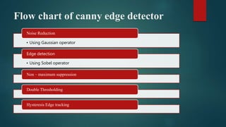
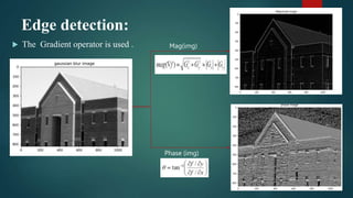
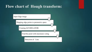
Department of Electronics and
Communication Engineering
EC6421D Digital Image ProcessingTechniques
Mini Project
Naman Jain(M220327EC)
Shubham loni(M220305EC)
Line detection through Hough transform
Contents
 Introduction
 Process of line detection
 Canny edge detector
 Flow chart of canny edge detector
 Hough Concept
 Flow chart of Hough transform
 Output
 Applications
 Examples
 References
INTRODUCTION
 Can we fit lines, circles, ellipse or any other shape to link the edges?
 “YES”.
 The Hough transform is basically used for extracting feature from
the image such as outlining , boundary , corners present in the
image.
 The key idea of Hough transform is that if two edges points lay on
the same line, their corresponding cosine curves or lines will
intersect each other on a specific parametric plane.
Input
image
Edge
detection
Hough
transform
Output
Image
Process of Line Detection
Canny Edge Detector
 The Canny edge detector is an edge detection method that has
multistage algorithm to detect the wide range of edges in an image
 It was developed by John F. Canny in 1986.
 Canny edge detection is a technique to extract useful structural
information from different vision objects and dramatically reduce the
amount of data to be processed.
 It has been widely applied in various computer visionsystems.
Flow chart of canny edge detector
• Using Gaussian operator
Noise Reduction
• Using Sobel operator
Edge detection
Non – maximum suppression
Double Thresholding
Hysteresis Edge tracking
Noise Reduction :
 It is basically a smoothing technique.
 In an image noise consist of sharp transition in intensity
 To eliminate those noise spatial filters are used such as box filter , weighted averages and
Gaussian filter.
 Gaussian smoothing is widely used.
Edge detection:
 The Gradient operator is used . Mag(img)
Phase (img)
Non-maximum suppression:
 Original phase is Quantize into one of the four different phases.
 Go in the direction specified by the gradient ,then check the
neighbouring pixel .
 If lower then the centre pixel then treated as edge.
Double Thresholding and Hysteresis:
 Here we are taking Double Thresholding instead of standard way of
threshold.
 The double threshold step aims at identifying 3 kind of pixels :strong
,weak and non relevant .
 Strong:- pixels having intensities so high that they are surely
contribute to final edge.
 Weak:- pixels having intensities so low , that is not enough to be
consider as strong ones but yet not small enough to be consider non-
relevant to be an edge.
 Other pixels are consider to be non-relevant to the edge.
Canny Edge Image
Hough Transform
• Elegant method for direct object recognition
• Edges need not be connected
• Complete object need not be visible
• Key Idea: Edges VOTE for the possible model
Flow chart of Hough transform:
Input Edge image
Mapping edge points to parametric space
Creating ACUMULATOR
Find the point with maximum voting
Detection of Line
Hough Transform: Concept
Line Grouping Problem
The Straight Line
(x1,y1)
(x2,y2)
• For each point (x , y) in the line the following
equation applies:
• Therefore:
𝑦 = 𝑚 ⋅ 𝑥 + 𝑐
Multiple Lines over a single point
 Each pair (m , b) defines a
distinct straight line
containing the point (x,y)
(x,y)
y=m1x+b1
y=m2x+b2
y=m3x+b3
y=m4x+b4
The Parameter Plane
 Each point in the (x,y)
space(image plane) is mapped
to a straight line in the (m ,b)
space (parameter plane).
 A straight line in the (x,y)
space (image plane) is
mapped to the intersection
point of the lines
corresponding to its points, in
the (m.b) space (parameter
plane).
b =-mx1+y1
(x1,y1)
(x2,y2)
(x3,y3)
b =-mx3+y3
b =-mx2+y2
The Accumulator Concept
 The (m.b) space (parameter
plane) is subdivided in
cells.
 Each pixel (x,y) in the
original image vote in the
(m, b) space for each line
passing through it.
 The votes are summed in an
Accumulator
m
mmin mmax
b1
m1
N
Corresponds to a straight line
y=m1x+b1
of N pixels length
b
The Motivation for Polar Coordinates
 Vertical lines cannot be mapped
to the (m,b) space, since:
 Vertical lines can be described
using polar coordinates :
x = r
r
?



b
m
xcos0 + ysin0 = r
Using Polar Coordinates
• For each point (x,y) in
the line the following
equation applies:
• In particular: (x1,y1)
(x2,y2)
r
θ






sin
cos
sin
cos
sin
cos
2
2
1
1
y
x
r
y
x
r
y
x
r







 sin
cos y
x
r 

r = x · cos θ + y · sin θ
For given point (0,2) , (2,0), (1,1)
Input Image Output Image
Output
Examples
Applications
 It is widely used in feature extraction (shapes of the objects).
 Another big advantage is used for the building-edge extraction.
 It can extract the lines even through the noisy data.
 By the Hough transform, we can detect the missing lines which are
broken while detecting edge image.
 We can use it in lane detection of the road.
REFRENCE
 Names: Gonzalez, Rafael C., author. | Woods, Richard E. (Richard Eugene), author
 Wikipedia, Internet search
 https://ieeexplore.ieee.org/document/6949962 DOI :- 10.1109/ICCSP.2014.6949962
 https://ieeexplore.ieee.org/document/9422200 DOI :- 10.1109/TPAMI.2021.3077129
Thank You

Line Detection using Hough transform .pptx

  • 1.
    Department of Electronicsand Communication Engineering EC6421D Digital Image ProcessingTechniques Mini Project Naman Jain(M220327EC) Shubham loni(M220305EC) Line detection through Hough transform
  • 2.
    Contents  Introduction  Processof line detection  Canny edge detector  Flow chart of canny edge detector  Hough Concept  Flow chart of Hough transform  Output  Applications  Examples  References
  • 3.
    INTRODUCTION  Can wefit lines, circles, ellipse or any other shape to link the edges?  “YES”.  The Hough transform is basically used for extracting feature from the image such as outlining , boundary , corners present in the image.  The key idea of Hough transform is that if two edges points lay on the same line, their corresponding cosine curves or lines will intersect each other on a specific parametric plane.
  • 4.
  • 5.
    Canny Edge Detector The Canny edge detector is an edge detection method that has multistage algorithm to detect the wide range of edges in an image  It was developed by John F. Canny in 1986.  Canny edge detection is a technique to extract useful structural information from different vision objects and dramatically reduce the amount of data to be processed.  It has been widely applied in various computer visionsystems.
  • 6.
    Flow chart ofcanny edge detector • Using Gaussian operator Noise Reduction • Using Sobel operator Edge detection Non – maximum suppression Double Thresholding Hysteresis Edge tracking
  • 7.
    Noise Reduction : It is basically a smoothing technique.  In an image noise consist of sharp transition in intensity  To eliminate those noise spatial filters are used such as box filter , weighted averages and Gaussian filter.  Gaussian smoothing is widely used.
  • 8.
    Edge detection:  TheGradient operator is used . Mag(img) Phase (img)
  • 9.
    Non-maximum suppression:  Originalphase is Quantize into one of the four different phases.  Go in the direction specified by the gradient ,then check the neighbouring pixel .  If lower then the centre pixel then treated as edge.
  • 10.
    Double Thresholding andHysteresis:  Here we are taking Double Thresholding instead of standard way of threshold.  The double threshold step aims at identifying 3 kind of pixels :strong ,weak and non relevant .  Strong:- pixels having intensities so high that they are surely contribute to final edge.  Weak:- pixels having intensities so low , that is not enough to be consider as strong ones but yet not small enough to be consider non- relevant to be an edge.  Other pixels are consider to be non-relevant to the edge.
  • 11.
  • 12.
    Hough Transform • Elegantmethod for direct object recognition • Edges need not be connected • Complete object need not be visible • Key Idea: Edges VOTE for the possible model
  • 13.
    Flow chart ofHough transform: Input Edge image Mapping edge points to parametric space Creating ACUMULATOR Find the point with maximum voting Detection of Line
  • 14.
  • 15.
  • 16.
    The Straight Line (x1,y1) (x2,y2) •For each point (x , y) in the line the following equation applies: • Therefore: 𝑦 = 𝑚 ⋅ 𝑥 + 𝑐
  • 17.
    Multiple Lines overa single point  Each pair (m , b) defines a distinct straight line containing the point (x,y) (x,y) y=m1x+b1 y=m2x+b2 y=m3x+b3 y=m4x+b4
  • 18.
    The Parameter Plane Each point in the (x,y) space(image plane) is mapped to a straight line in the (m ,b) space (parameter plane).  A straight line in the (x,y) space (image plane) is mapped to the intersection point of the lines corresponding to its points, in the (m.b) space (parameter plane). b =-mx1+y1 (x1,y1) (x2,y2) (x3,y3) b =-mx3+y3 b =-mx2+y2
  • 19.
    The Accumulator Concept The (m.b) space (parameter plane) is subdivided in cells.  Each pixel (x,y) in the original image vote in the (m, b) space for each line passing through it.  The votes are summed in an Accumulator m mmin mmax b1 m1 N Corresponds to a straight line y=m1x+b1 of N pixels length b
  • 20.
    The Motivation forPolar Coordinates  Vertical lines cannot be mapped to the (m,b) space, since:  Vertical lines can be described using polar coordinates : x = r r ?    b m xcos0 + ysin0 = r
  • 21.
    Using Polar Coordinates •For each point (x,y) in the line the following equation applies: • In particular: (x1,y1) (x2,y2) r θ       sin cos sin cos sin cos 2 2 1 1 y x r y x r y x r         sin cos y x r  
  • 22.
    r = x· cos θ + y · sin θ For given point (0,2) , (2,0), (1,1)
  • 23.
    Input Image OutputImage Output
  • 24.
  • 25.
    Applications  It iswidely used in feature extraction (shapes of the objects).  Another big advantage is used for the building-edge extraction.  It can extract the lines even through the noisy data.  By the Hough transform, we can detect the missing lines which are broken while detecting edge image.  We can use it in lane detection of the road.
  • 29.
    REFRENCE  Names: Gonzalez,Rafael C., author. | Woods, Richard E. (Richard Eugene), author  Wikipedia, Internet search  https://ieeexplore.ieee.org/document/6949962 DOI :- 10.1109/ICCSP.2014.6949962  https://ieeexplore.ieee.org/document/9422200 DOI :- 10.1109/TPAMI.2021.3077129
  • 30.