The document provides an introduction to Mode S secondary surveillance radar systems, detailing operations, specifications, and communication protocols between interrogators and transponders. It covers various aspects such as the dialogue during interrogations, optimal register extraction, and the impact of codes on communication. Additionally, it discusses acquisition strategies and the performance of the system while referencing International Civil Aviation Organization standards.


![22
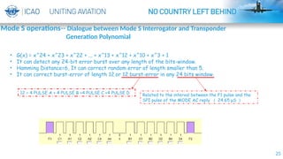
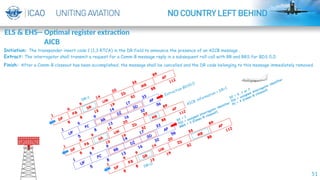
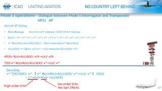
PI =17 zero + CL (3 bits ) + IC ( 4 bits ) =PI ( x )
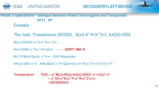
Transponder --- Transmission: T(x)=x^24 M(x) + R(x)+ PI(x)
Radar---Reception : [x^24 M(x) + R(x)+ PI(x)]/G(x) = Q(x) + 0+ [PI(x)/G(x)]
The remainder = PI(x)
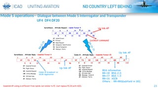
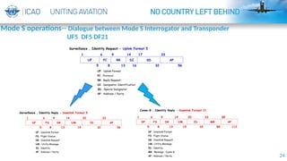
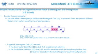
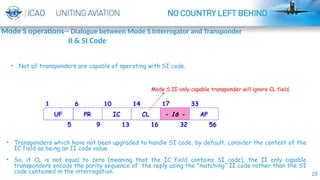
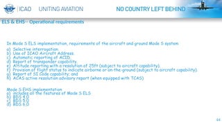
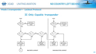
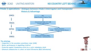
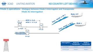
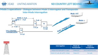
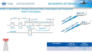
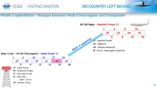
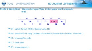
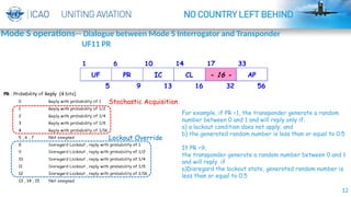
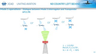
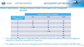
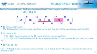
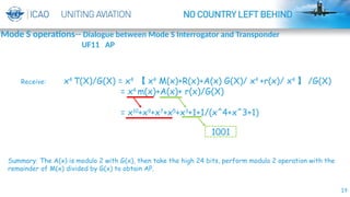
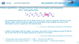
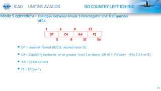
Mode S operations-- Dialogue between Mode S Interrogator and Transponder
DF11](https://image.slidesharecdn.com/introductiontomodesradarsystem-presentedversion-250107213657-82b07e52/85/Introduction-to-Mode-S-Radar-System-Presented-Version-pptx-22-320.jpg)