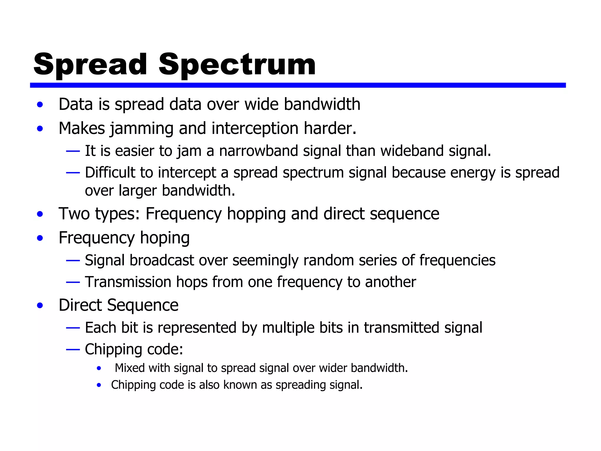
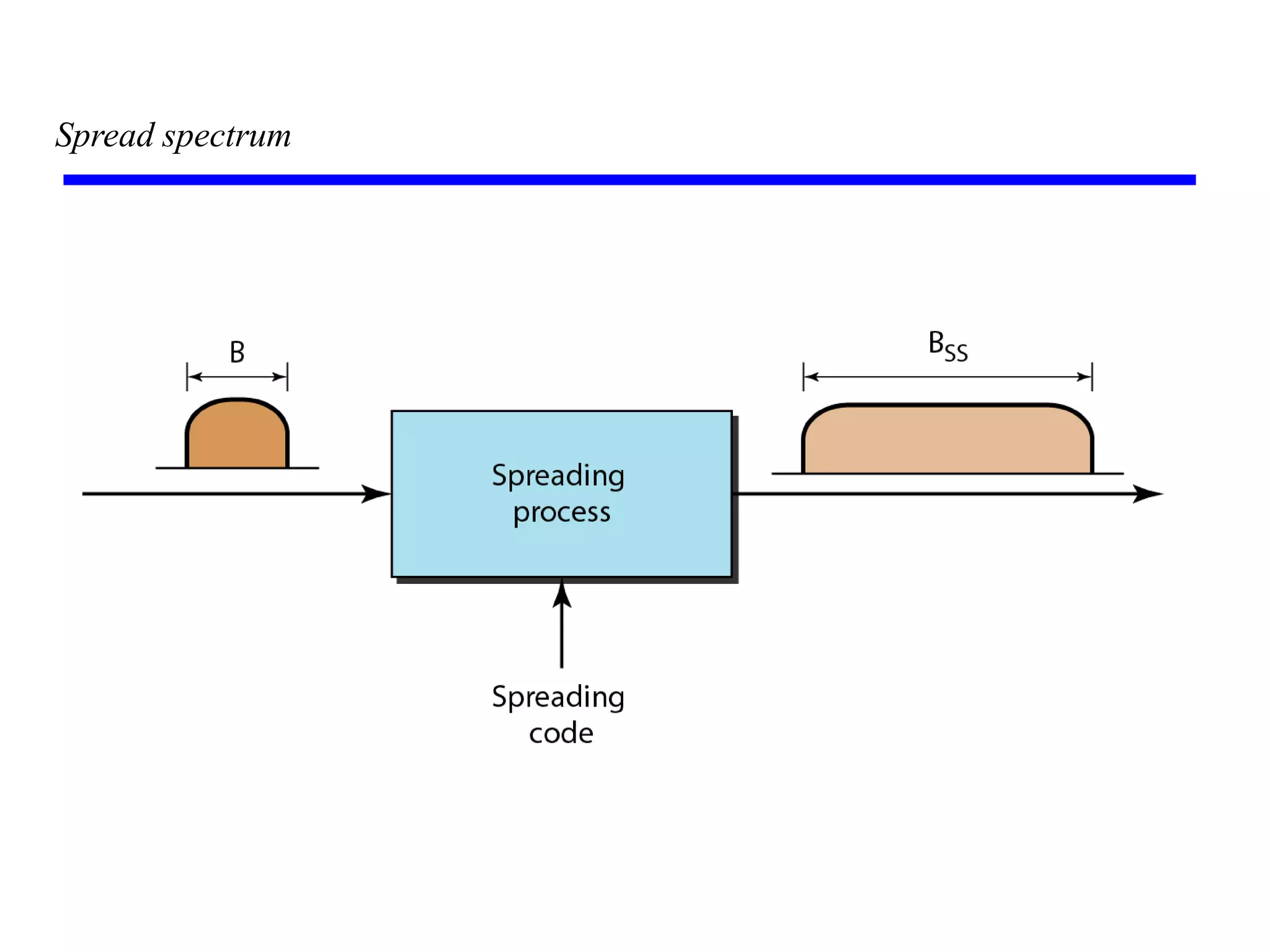
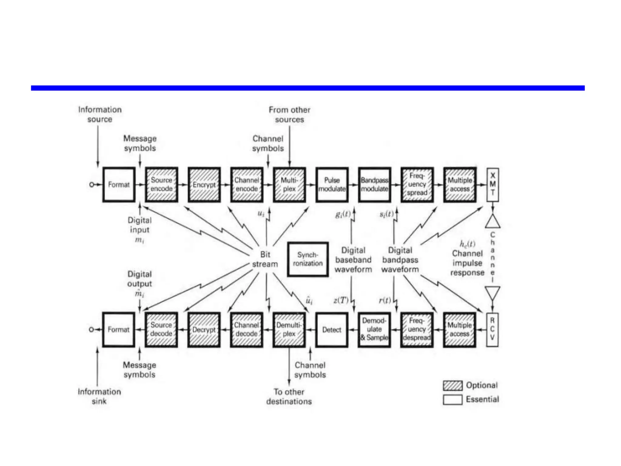
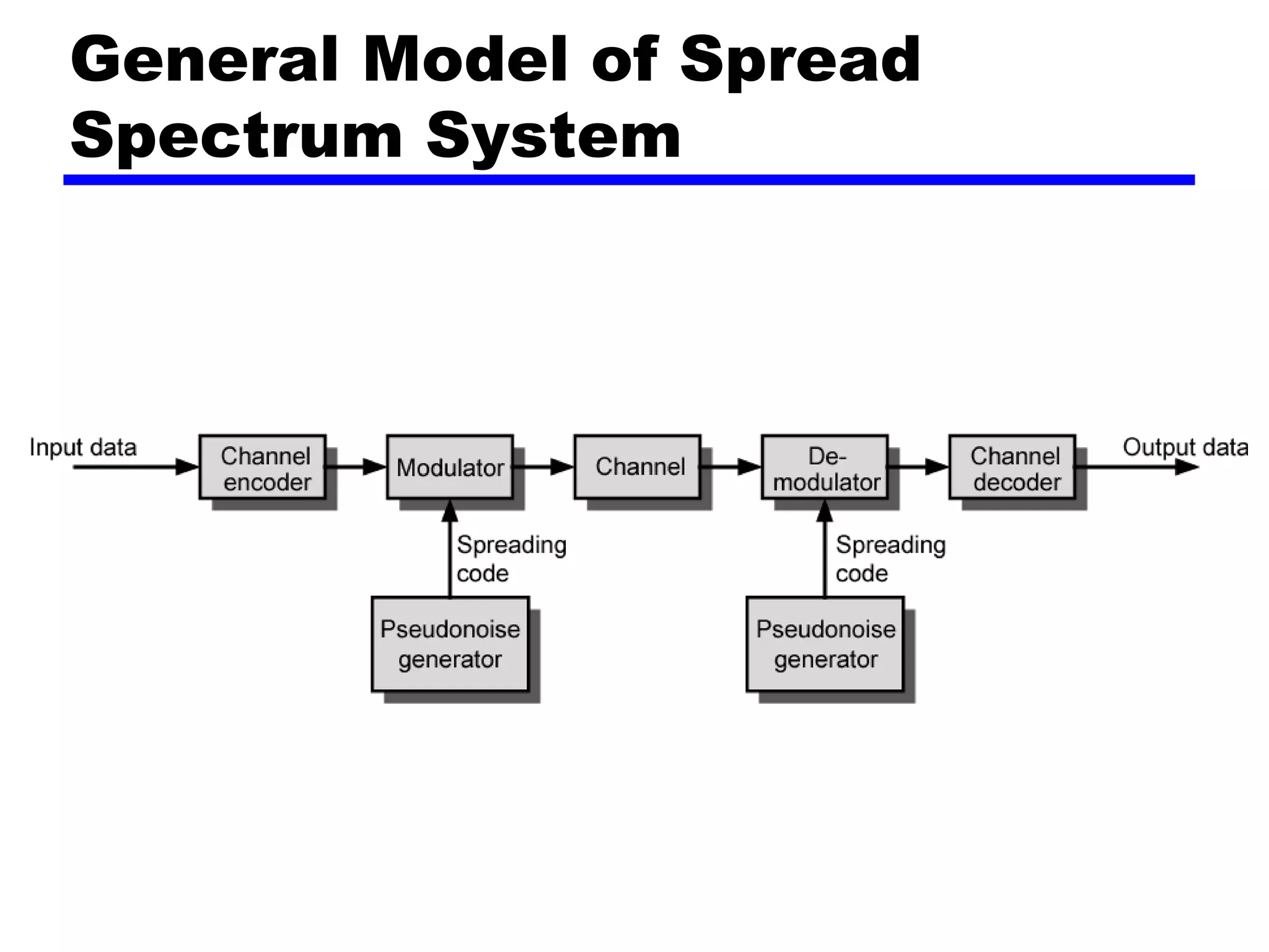
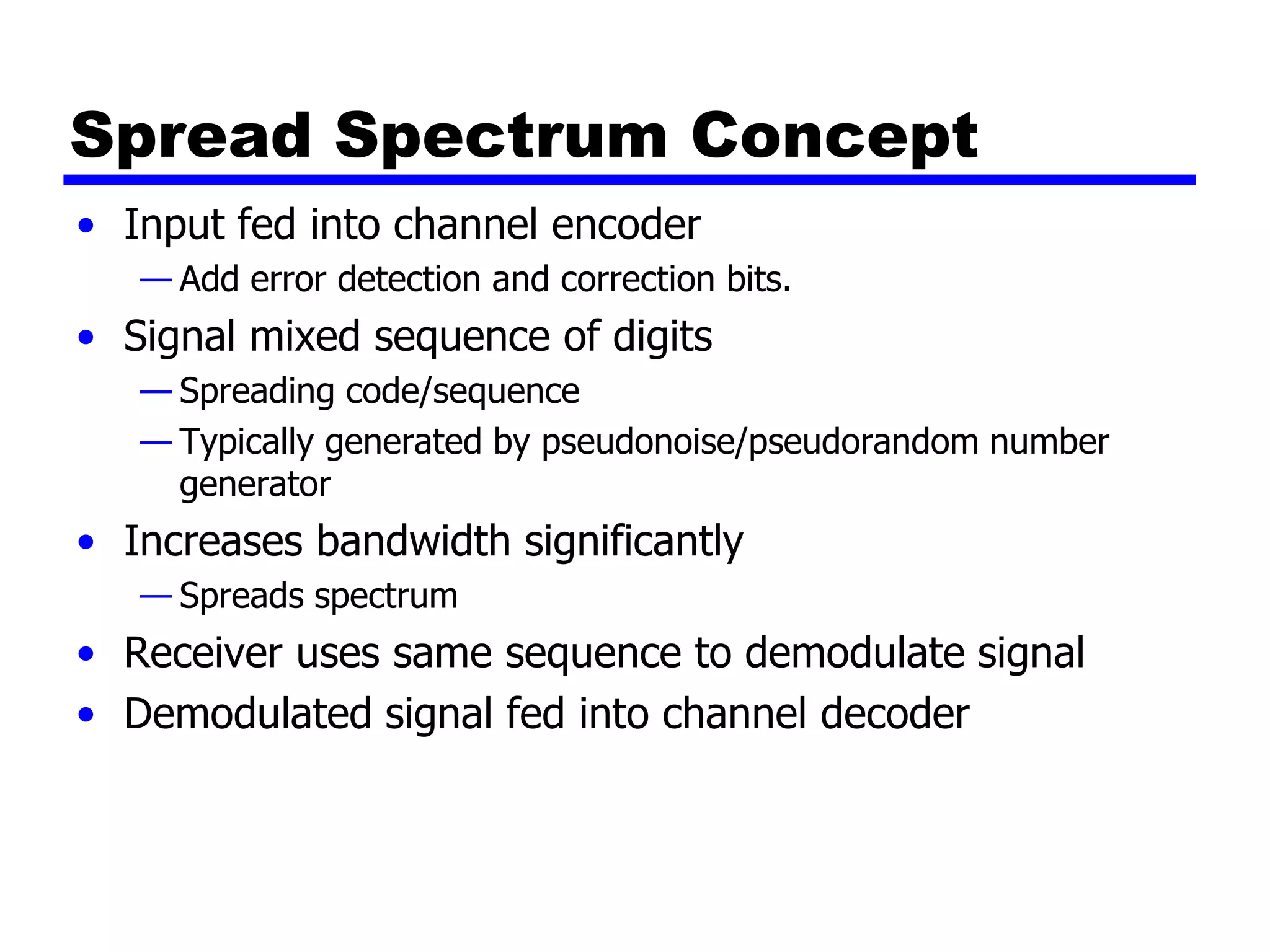
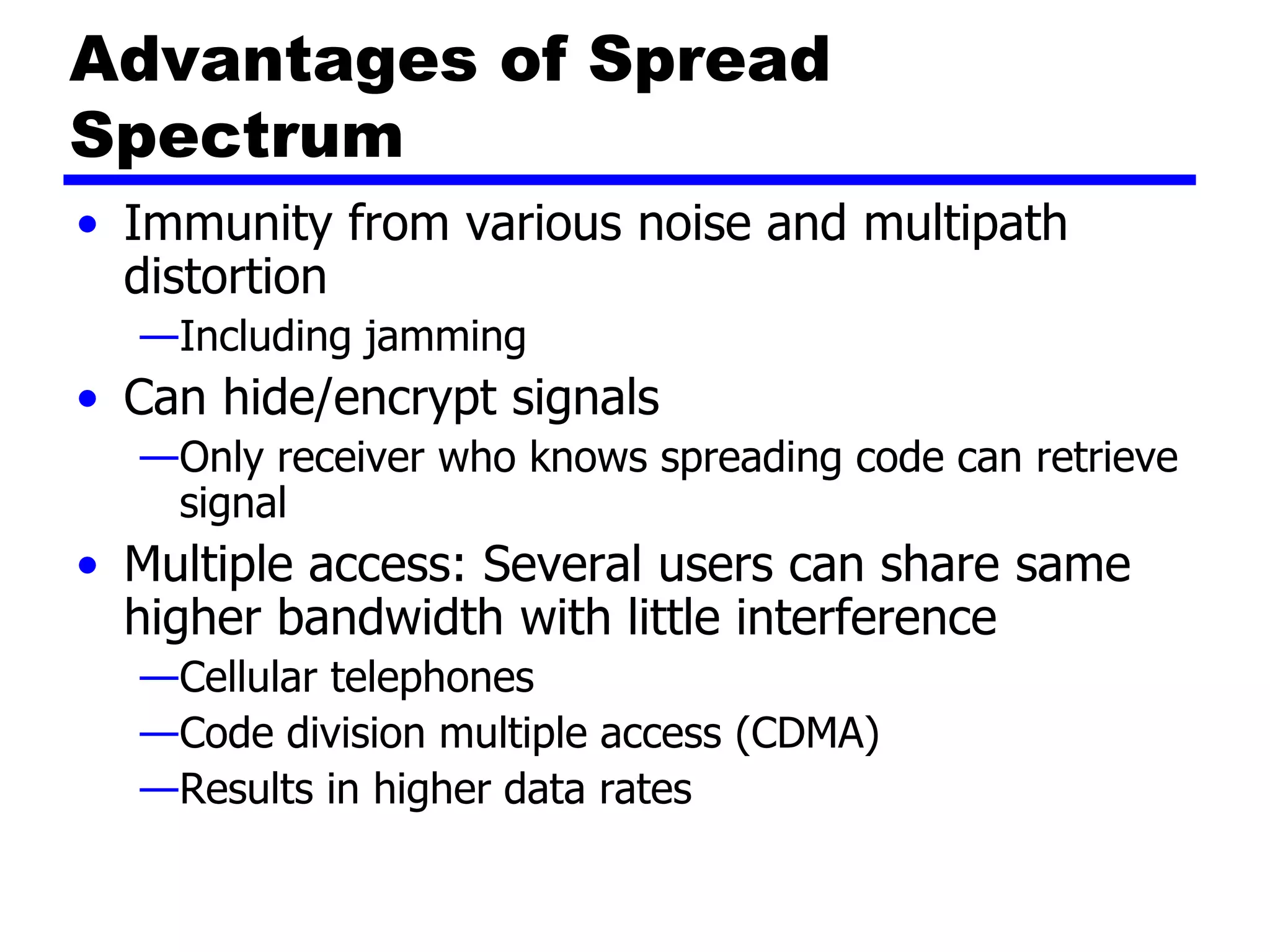
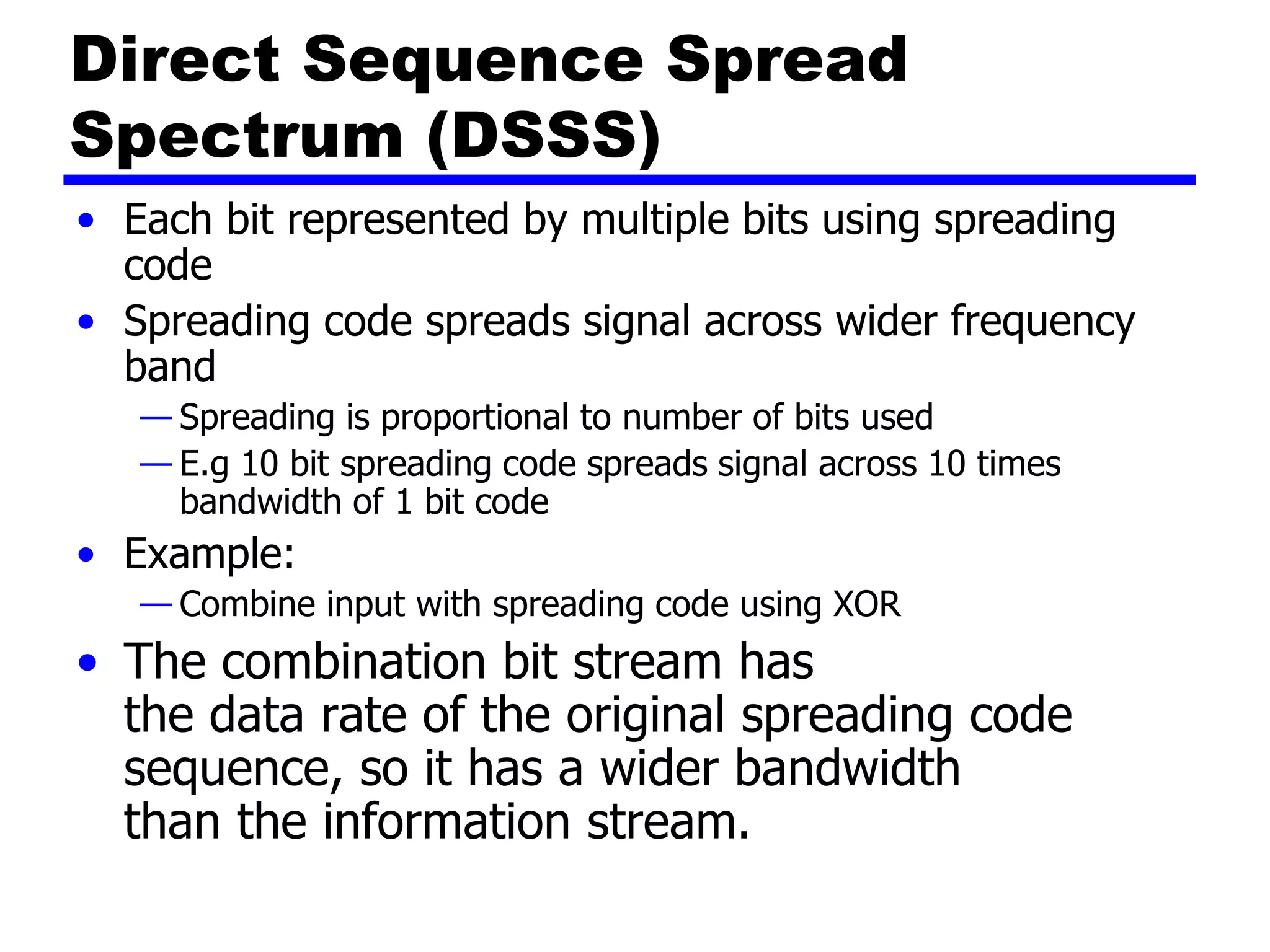
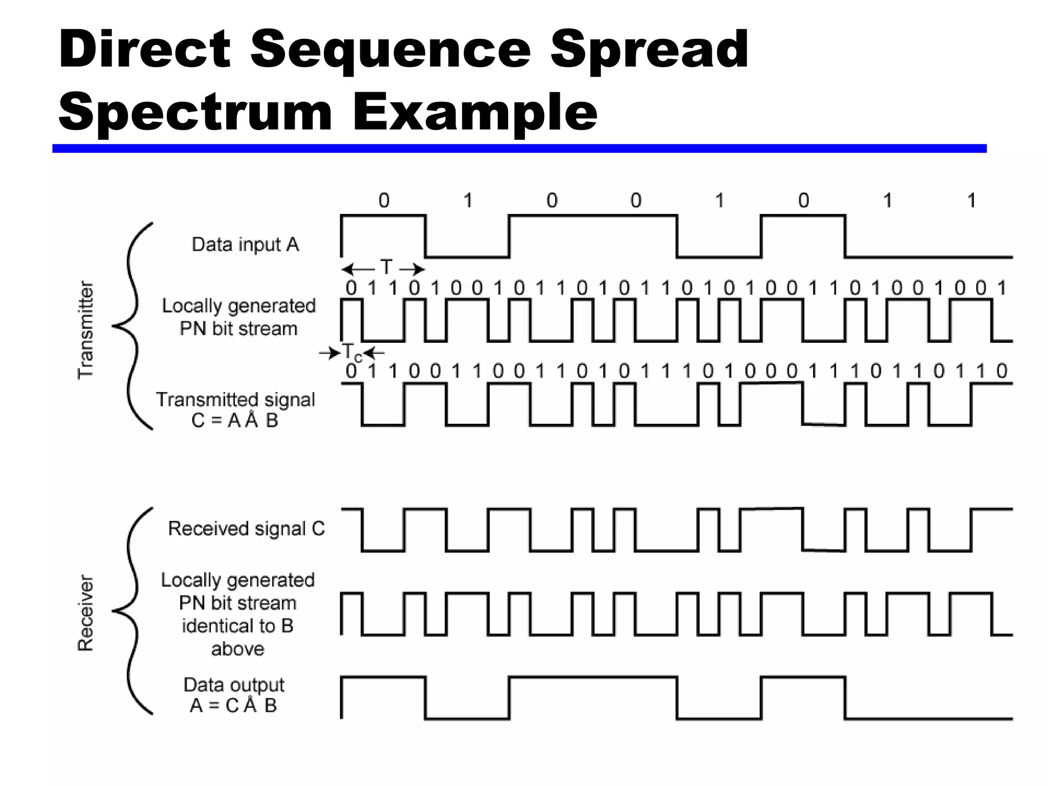
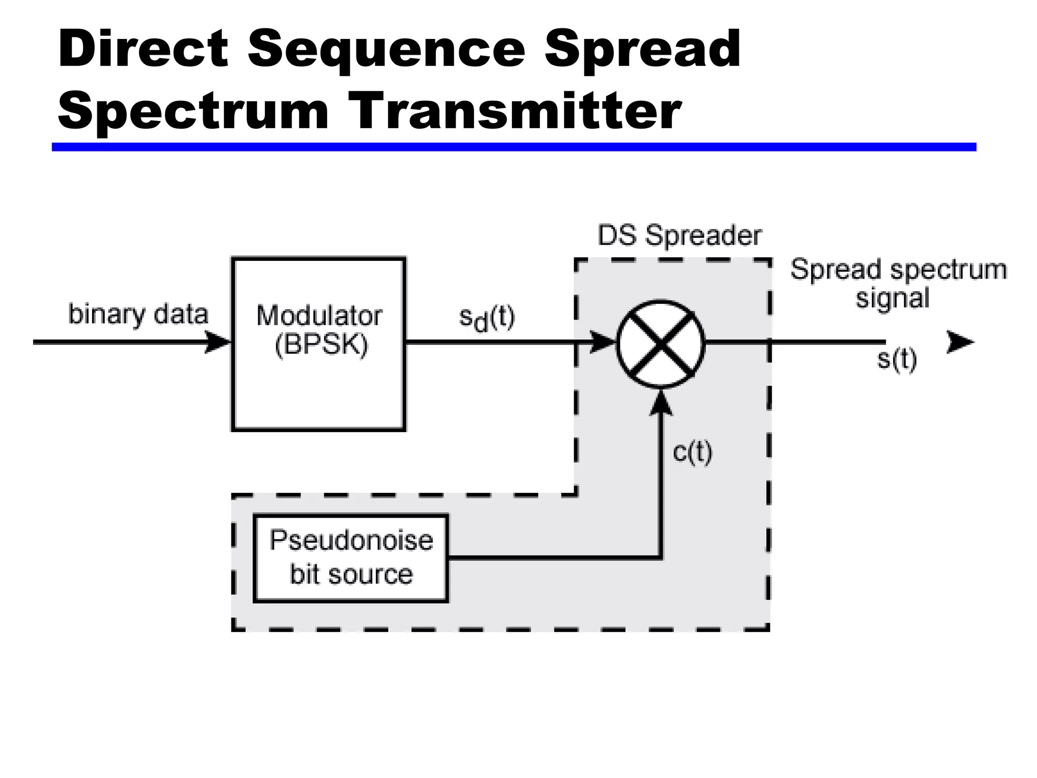
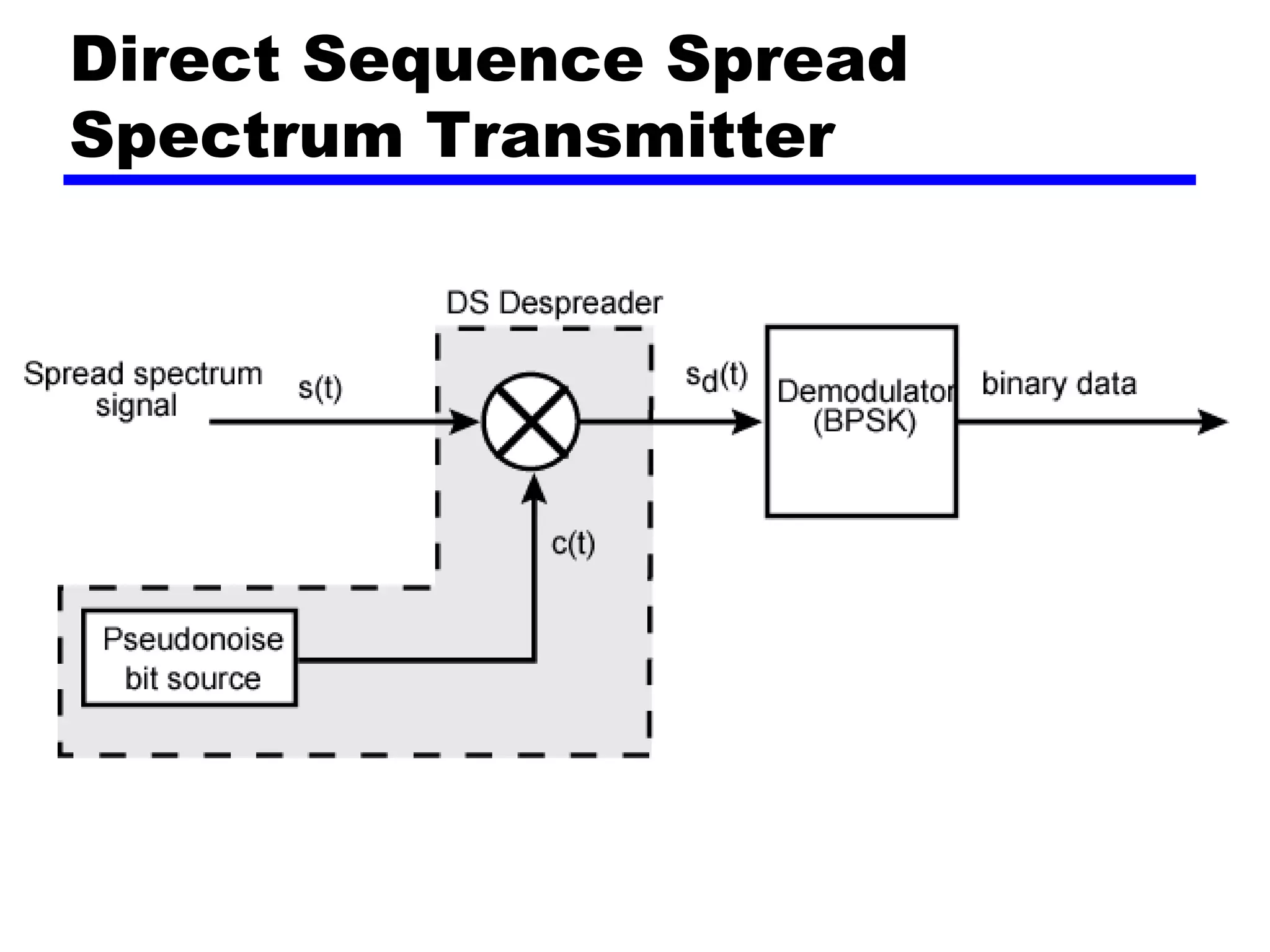
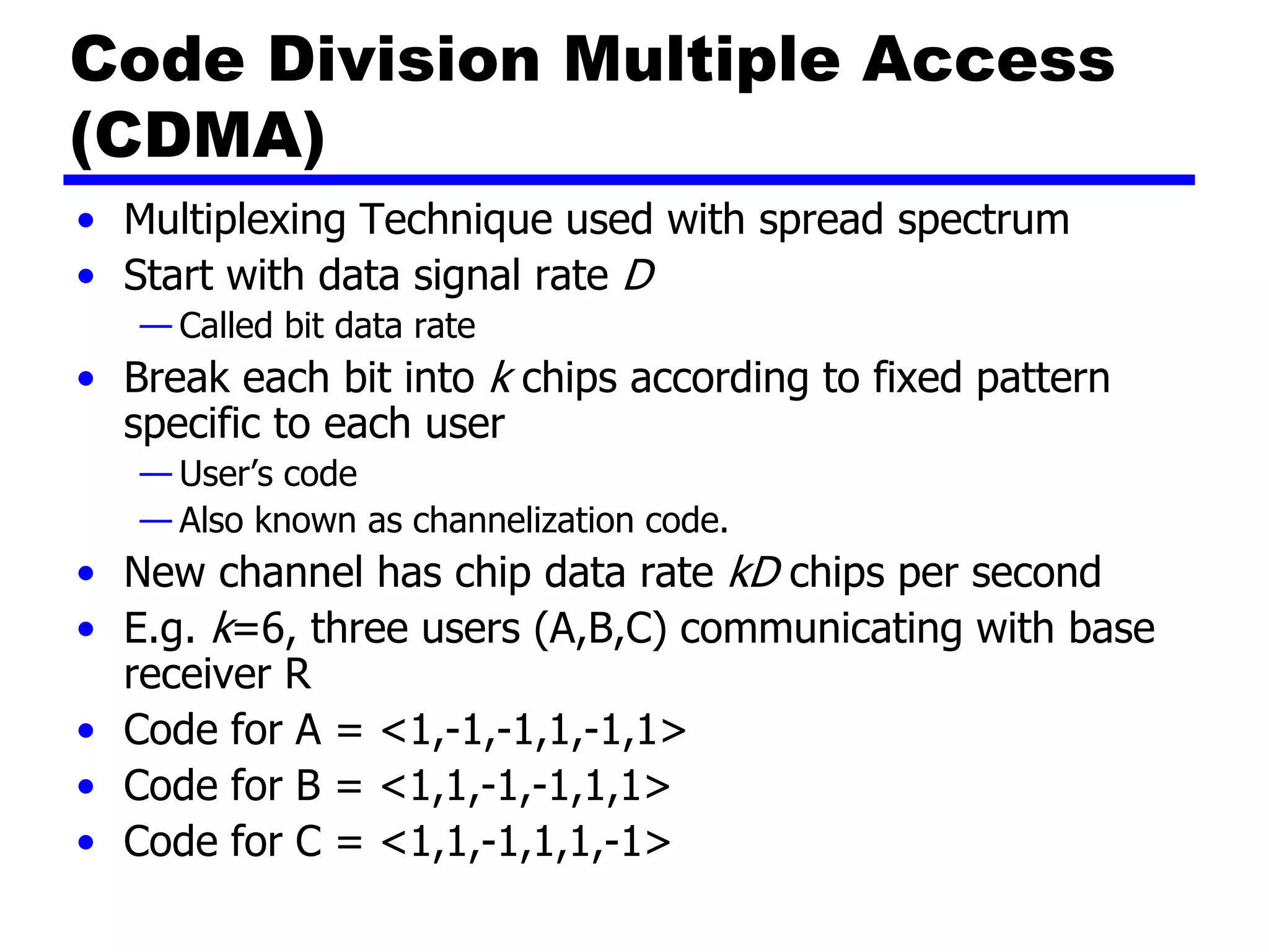
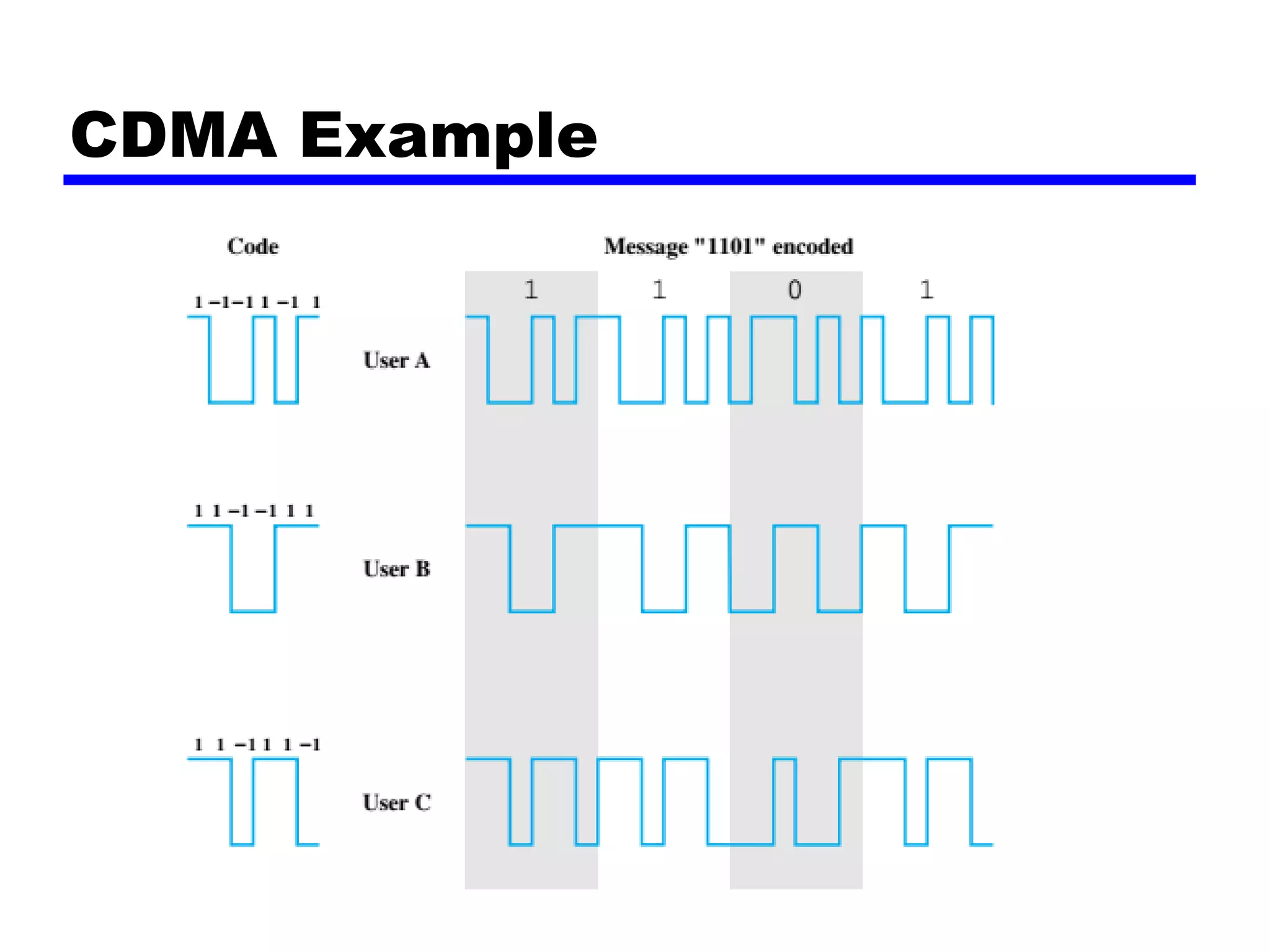
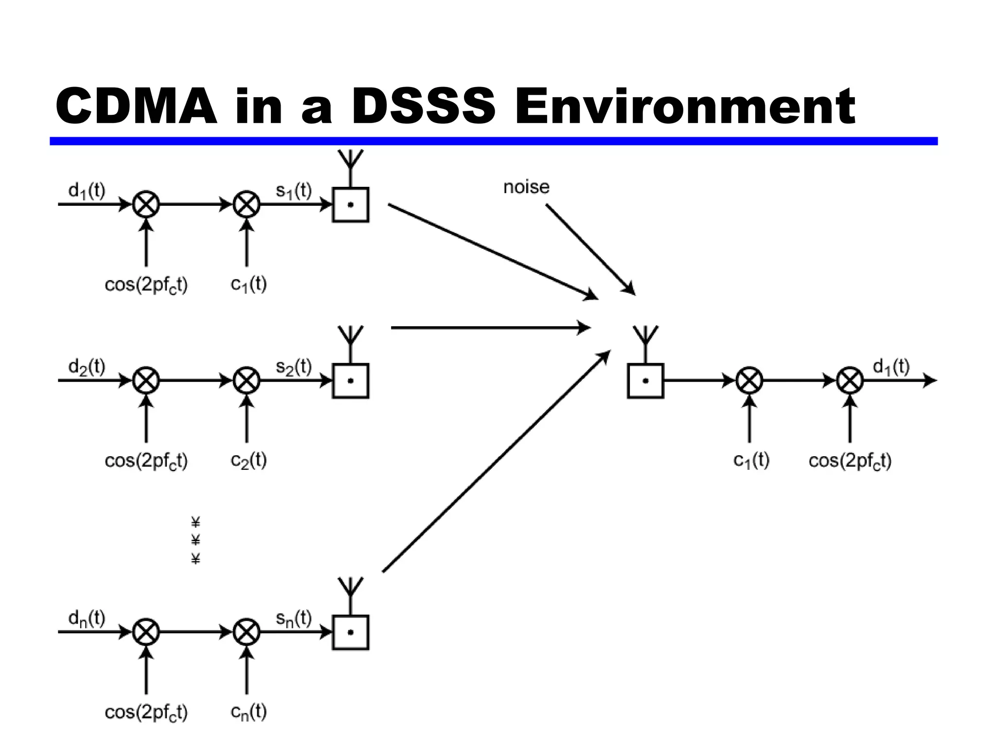
Spread Spectrum
Spread Spectrum
• Data is spread data over wide bandwidth
• Makes jamming and interception harder.
— It is easier to jam a narrowband signal than wideband signal.
— Difficult to intercept a spread spectrum signal because energy is spread
over larger bandwidth.
• Two types: Frequency hopping and direct sequence
• Frequency hoping
— Signal broadcast over seemingly random series of frequencies
— Transmission hops from one frequency to another
• Direct Sequence
— Each bit is represented by multiple bits in transmitted signal
— Chipping code:
• Mixed with signal to spread signal over wider bandwidth.
• Chipping code is also known as spreading signal.
Spread spectrum
General Model of Spread
Spectrum System
Spread Spectrum Concept
• Input fed into channel encoder
— Add error detection and correction bits.
• Signal mixed sequence of digits
— Spreading code/sequence
— Typically generated by pseudonoise/pseudorandom number
generator
• Increases bandwidth significantly
— Spreads spectrum
• Receiver uses same sequence to demodulate signal
• Demodulated signal fed into channel decoder
Advantages of Spread
Spectrum
• Immunity from various noise and multipath
distortion
—Including jamming
• Can hide/encrypt signals
—Only receiver who knows spreading code can retrieve
signal
• Multiple access: Several users can share same
higher bandwidth with little interference
—Cellular telephones
—Code division multiple access (CDMA)
—Results in higher data rates
Frequency Hopping Spread
Spectrum (FHSS)
• Signal broadcast over seemingly random series
of frequencies
• Receiver hops between frequencies in sync with
transmitter
• FHSS not severely affected by jamming:
—Jamming on one frequency affects only a few bits
Frequency Hopping Spread
Spectrum System (Transmitter)
Basic Operation
• A pseudonoise (PN), or pseudorandom number,
source serves as an index into a table
of frequencies;
—This is the spreading code referred to previously.
• PN sequence is of length k bits
• Typically 2k carriers frequencies forming 2k
channels
• Each k bits of the PN source specifies one of the
carrier frequencies.
Frequency Hopping Spread
Spectrum System (Receiver)
Basic Operation
• At each successive interval (each k PN bits), a
new carrier frequency is selected.
• This frequency is then modulated by the signal
produced from the initial modulator to produce
a new signal with the same shape but now
centered on the selected carrier frequency.
• On reception the spread spectrum signal is
demodulated using the same sequence of PN-
derived frequencies and then demodulated to
produce the output data.
Frequency Hopping Example
FHSS Performance
Considerations
• Typically large number of frequencies used
—Improved resistance to jamming
Direct Sequence Spread
Spectrum (DSSS)
• Each bit represented by multiple bits using spreading
code
• Spreading code spreads signal across wider frequency
band
— Spreading is proportional to number of bits used
— E.g 10 bit spreading code spreads signal across 10 times
bandwidth of 1 bit code
• Example:
— Combine input with spreading code using XOR
• The combination bit stream has
the data rate of the original spreading code
sequence, so it has a wider bandwidth
than the information stream.
Direct Sequence Spread
Spectrum Example
Direct Sequence Spread
Spectrum Transmitter
Direct Sequence Spread
Spectrum Transmitter
Approximate
Spectrum of
DSSS Signal
Code Division Multiple Access
(CDMA)
• Multiplexing Technique used with spread spectrum
• Start with data signal rate D
— Called bit data rate
• Break each bit into k chips according to fixed pattern
specific to each user
— User’s code
— Also known as channelization code.
• New channel has chip data rate kD chips per second
• E.g. k=6, three users (A,B,C) communicating with base
receiver R
• Code for A = <1,-1,-1,1,-1,1>
• Code for B = <1,1,-1,-1,1,1>
• Code for C = <1,1,-1,1,1,-1>
CDMA Example
CDMA Explanation
• Consider A communicating with base
• Base station knows A’s code
• Assume communication already synchronized
• A wants to send a 1
— Send chip pattern <1,-1,-1,1,-1,1>
• A’s code
• A wants to send 0
— Send chip[ pattern <-1,1,1,-1,1,-1>
• Complement of A’s code
CDMA Explanation
• Decoder ignores other sources when using A’s
code to decode because the chipping codes are
orthogonal
• The codes of A and B that have the property
that are called orthogonal if, for example:
CDMA for DSSS
• n users each using different orthogonal PN
sequence
• Modulate each users data stream
—Using BPSK
• Multiply by spreading code of user
CDMA in a DSSS Environment

Lecture spread spectrum

  • 1.
  • 2.
    Spread Spectrum • Datais spread data over wide bandwidth • Makes jamming and interception harder. — It is easier to jam a narrowband signal than wideband signal. — Difficult to intercept a spread spectrum signal because energy is spread over larger bandwidth. • Two types: Frequency hopping and direct sequence • Frequency hoping — Signal broadcast over seemingly random series of frequencies — Transmission hops from one frequency to another • Direct Sequence — Each bit is represented by multiple bits in transmitted signal — Chipping code: • Mixed with signal to spread signal over wider bandwidth. • Chipping code is also known as spreading signal.
  • 3.
  • 5.
    General Model ofSpread Spectrum System
  • 6.
    Spread Spectrum Concept •Input fed into channel encoder — Add error detection and correction bits. • Signal mixed sequence of digits — Spreading code/sequence — Typically generated by pseudonoise/pseudorandom number generator • Increases bandwidth significantly — Spreads spectrum • Receiver uses same sequence to demodulate signal • Demodulated signal fed into channel decoder
  • 7.
    Advantages of Spread Spectrum •Immunity from various noise and multipath distortion —Including jamming • Can hide/encrypt signals —Only receiver who knows spreading code can retrieve signal • Multiple access: Several users can share same higher bandwidth with little interference —Cellular telephones —Code division multiple access (CDMA) —Results in higher data rates
  • 8.
    Frequency Hopping Spread Spectrum(FHSS) • Signal broadcast over seemingly random series of frequencies • Receiver hops between frequencies in sync with transmitter • FHSS not severely affected by jamming: —Jamming on one frequency affects only a few bits
  • 9.
  • 10.
    Basic Operation • Apseudonoise (PN), or pseudorandom number, source serves as an index into a table of frequencies; —This is the spreading code referred to previously. • PN sequence is of length k bits • Typically 2k carriers frequencies forming 2k channels • Each k bits of the PN source specifies one of the carrier frequencies.
  • 11.
  • 12.
    Basic Operation • Ateach successive interval (each k PN bits), a new carrier frequency is selected. • This frequency is then modulated by the signal produced from the initial modulator to produce a new signal with the same shape but now centered on the selected carrier frequency. • On reception the spread spectrum signal is demodulated using the same sequence of PN- derived frequencies and then demodulated to produce the output data.
  • 13.
  • 14.
    FHSS Performance Considerations • Typicallylarge number of frequencies used —Improved resistance to jamming
  • 15.
    Direct Sequence Spread Spectrum(DSSS) • Each bit represented by multiple bits using spreading code • Spreading code spreads signal across wider frequency band — Spreading is proportional to number of bits used — E.g 10 bit spreading code spreads signal across 10 times bandwidth of 1 bit code • Example: — Combine input with spreading code using XOR • The combination bit stream has the data rate of the original spreading code sequence, so it has a wider bandwidth than the information stream.
  • 16.
  • 17.
  • 18.
  • 19.
  • 20.
    Code Division MultipleAccess (CDMA) • Multiplexing Technique used with spread spectrum • Start with data signal rate D — Called bit data rate • Break each bit into k chips according to fixed pattern specific to each user — User’s code — Also known as channelization code. • New channel has chip data rate kD chips per second • E.g. k=6, three users (A,B,C) communicating with base receiver R • Code for A = <1,-1,-1,1,-1,1> • Code for B = <1,1,-1,-1,1,1> • Code for C = <1,1,-1,1,1,-1>
  • 21.
  • 22.
    CDMA Explanation • ConsiderA communicating with base • Base station knows A’s code • Assume communication already synchronized • A wants to send a 1 — Send chip pattern <1,-1,-1,1,-1,1> • A’s code • A wants to send 0 — Send chip[ pattern <-1,1,1,-1,1,-1> • Complement of A’s code
  • 23.
    CDMA Explanation • Decoderignores other sources when using A’s code to decode because the chipping codes are orthogonal • The codes of A and B that have the property that are called orthogonal if, for example:
  • 24.
    CDMA for DSSS •n users each using different orthogonal PN sequence • Modulate each users data stream —Using BPSK • Multiply by spreading code of user
  • 25.
    CDMA in aDSSS Environment