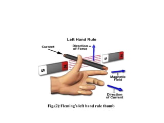
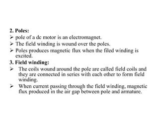
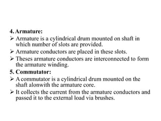
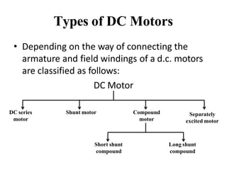
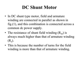
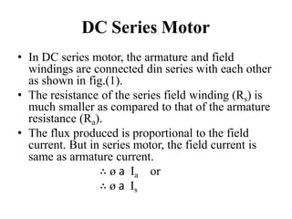
DC
MOTOR
Introduction
• The Dc machines are of two types namely DC
generators and DC motors.
• ADC generators converts mechanical energy into
electrical energy whereas a DC motor converts
the electrical energy into mechanical energy.
• In order to understand the operating principle of a
DC motor, it is necessary to understand how does
a current carrying conductor experience a force,
when kept in a magnetic field.
• Force on current carrying conductor:
If a straight conductor is placed in the
magnetic field produced by a permanent
magnet, the current flowing through a
conductor in anti clockwise direction.
Due to the presence of two magnetic fields
simultaneously, an interaction between them
will take place as shown in fig.(1).
• Magnitude of Force:
The magnitude of the force experienced by the
current carrying conductor placed in the
magnetic field is given by,
F = BIl Newton
Where B = Flux density produced by Magnet
I = current flowing through conductor
l = Length of the conductor
Fig.(2):Fleming’s left hand rule thumb
DC Motor
• Principle of operation:
When current carrying conductor is placed in
a magnetic field, it experienced a force.
In case of DC motor, the magnetic field us
developed by the field current i.e. current
flowing in field winding and armature winding
plays the role of current carrying conductor
So armature winding experienced a force and
start rotating.
Construction of DC Motor
Fig.(1): construction of DC motor
• Important parts of DC motor:
1. Yoke
2. Field winding
3. poles
4. Armature
5. Commutator, brushes & gear
6. Brushes
1. Yoke:
 It acts as the outer support of a DC motor.
 It provides mechanical support for the poles.
2. Poles:
 pole of a dc motor is an electromagnet.
 The field winding is wound over the poles.
 Poles produces magnetic flux when the filed winding is
excited.
3. Field winding:
 The coils wound around the pole are called field coils and
they are connected in series with each other to form field
winding.
 When current passing through the field winding, magnetic
flux produced in the air gap between pole and armature.
4.Armature:
 Armature is a cylindrical drum mounted on shaft in
which number of slots are provided.
 Armature conductors are placed in these slots.
 Theses armature conductors are interconnected to form
the armature winding.
5. Commutator:
 Acommutator is a cylindrical drum mounted on the
shaft alonwith the armature core.
 It collects the current from the armature conductors and
passed it to the external load via brushes.
6. Brushes:
Commutator is rotating. So it is not possible to
connect the load directly to it.
Hence current is conducted from the armature
to the external load by the carbon brushes
which are held against the surface of
commutator by springs.
Back EMF
• When the armature winding of a dc motor starts
rotating in the magnetic flux produced by the field
winding, it cuts the lines of magnetic flux.
• Hence according to the faraday’s laws of
electromagnetic induction, there will be an
induced emf in the armature winding.
• As per the Lenz’s law, this induced emf acts in
opposite direction to the armature supply voltage.
Hence this emf is called as the back emf and
denoted by Eb.
• Significance of back emf:
The presence of back e.m.f. makes the d.c. motor
a self -regulating machine i.e., it makes the motor
to draw as much armature current as is just
sufficient to develop the torque required by the
load.
1. When the motor is running on no load, small
torque is required to overcome the friction and
windage losses. Therefore, the armature current
Ia is small and the back e.m.f. is nearly equal to
the applied voltage.
Types of DC Motors
• Depending on the way of connecting the
armature and field windings of a d.c. motors
are classified as follows:
DC Motor
DC series
motor
Shunt motor Compound
motor
Separately
excited motor
Short shunt
compound
Long shunt
compound
DC Shunt Motor
• In DC shunt type motor, field and armature
winding are connected in parallel as shown in
fig.(1), and this combination is connected across a
common dc power supply.
• The resistance of shunt field winding (Rsh) is
always much higher than that of armature winding
(Ra).
• This is because the number of turns for the field
winding is more than that of armature winding.
• The field current Ish always remains constant.
Since V and Rsh both are constant. Hence flux
produced also remains constant. Because field
current is responsible for generation of flux.
∴ ø 𝖺 Ish
• This is why the shunt motor is also called as
the constant flux motors.
Fig.(1):DC shunt motor schematic diagram
DC Series Motor
• In DC series motor, the armature and field
windings are connected din series with each other
as shown in fig.(1).
• The resistance of the series field winding (Rs) is
much smaller as compared to that of the armature
resistance (Ra).
• The flux produced is proportional to the field
current. But in series motor, the field current is
same as armature current.
∴ ø 𝖺 Ia or
∴ ø 𝖺 Is
• The armature current Ia and hence field current
Is will be dependent on the load.
• Hence in DC series motor the flux does not
remains constant.
Fig.(1):DC series motor schematic diagram
DC Compound Motor
1. Long Shunt Compound Motor:
• As shown in fig.(1), in long shunt dc motor, shunt
field winding is connected across the series
combination of the armature and series field winding.
2. Short Shunt Compound Motor:
• In short shunt compound motor, armature and field
windings are connected in parallel with each other and
this combination is connected din series with the
series filed winding. This is shown in fig.(2).
 The long shunt and short shunt compound motors are
further classified as cumulative and differential
compound motors
Torque-speed characteristics
1. DC shunt motor:
• The torque-speed characteristics of dc shunt
motor is as shown in fig.(1).
• At no load, the torque produced by the motor is
Ta0 and the motor rotates at the no load speed N0.
• As the load increased, the torque requirement
also increase. To generate the required amount of
torque, the motor has to draw more armature
current.
• And more armature current can be drawn if the
more speed decreases.
• Therefore, as the load increases, torque will
also increase and the speed decreases.
• However the reduction in speed is not
significant as the load is increased from no
load to full load. Therefore practically the dc
shunt motor is called as a constant speed
motor.
Increase
in load
No load
Ta0
Constant speed
(ideal)
Practical
speed
Torque
Fig.(1):speed-torque characteristics of dc shunt motor
2. DC series motor:
• The speed –torque characteristics of DC series
motor is as shown in fig.(2).
• We know that
N 𝖺 1/ Ia and T 𝖺 I 2
a
N 𝖺 1/√T and Ia 𝖺 √T
• This shows that the speed decreases with
increase in the value of torque.
N 𝖺 (1/√T)
Fig.(2): speed-torque characteristics of dc series motor
3. DC compound motor:
• The torque- speed characteristics of the DC
compound motor is as shown in fig.(3).
• It is combination of characteristics of DC
series and DC shunt motor.
• The exact shape of these characteristics is
dependent on the precise effects of series and
shunt field winding.
Fig.(3): speed torque characteristics of dc compound motor

chapter-3-DC-motor-ppt-converted.pptx

  • 1.
  • 2.
    Introduction • The Dcmachines are of two types namely DC generators and DC motors. • ADC generators converts mechanical energy into electrical energy whereas a DC motor converts the electrical energy into mechanical energy. • In order to understand the operating principle of a DC motor, it is necessary to understand how does a current carrying conductor experience a force, when kept in a magnetic field.
  • 3.
    • Force oncurrent carrying conductor: If a straight conductor is placed in the magnetic field produced by a permanent magnet, the current flowing through a conductor in anti clockwise direction. Due to the presence of two magnetic fields simultaneously, an interaction between them will take place as shown in fig.(1).
  • 4.
    • Magnitude ofForce: The magnitude of the force experienced by the current carrying conductor placed in the magnetic field is given by, F = BIl Newton Where B = Flux density produced by Magnet I = current flowing through conductor l = Length of the conductor
  • 5.
  • 6.
    DC Motor • Principleof operation: When current carrying conductor is placed in a magnetic field, it experienced a force. In case of DC motor, the magnetic field us developed by the field current i.e. current flowing in field winding and armature winding plays the role of current carrying conductor So armature winding experienced a force and start rotating.
  • 7.
    Construction of DCMotor Fig.(1): construction of DC motor
  • 8.
    • Important partsof DC motor: 1. Yoke 2. Field winding 3. poles 4. Armature 5. Commutator, brushes & gear 6. Brushes 1. Yoke:  It acts as the outer support of a DC motor.  It provides mechanical support for the poles.
  • 9.
    2. Poles:  poleof a dc motor is an electromagnet.  The field winding is wound over the poles.  Poles produces magnetic flux when the filed winding is excited. 3. Field winding:  The coils wound around the pole are called field coils and they are connected in series with each other to form field winding.  When current passing through the field winding, magnetic flux produced in the air gap between pole and armature.
  • 10.
    4.Armature:  Armature isa cylindrical drum mounted on shaft in which number of slots are provided.  Armature conductors are placed in these slots.  Theses armature conductors are interconnected to form the armature winding. 5. Commutator:  Acommutator is a cylindrical drum mounted on the shaft alonwith the armature core.  It collects the current from the armature conductors and passed it to the external load via brushes.
  • 11.
    6. Brushes: Commutator isrotating. So it is not possible to connect the load directly to it. Hence current is conducted from the armature to the external load by the carbon brushes which are held against the surface of commutator by springs.
  • 12.
    Back EMF • Whenthe armature winding of a dc motor starts rotating in the magnetic flux produced by the field winding, it cuts the lines of magnetic flux. • Hence according to the faraday’s laws of electromagnetic induction, there will be an induced emf in the armature winding. • As per the Lenz’s law, this induced emf acts in opposite direction to the armature supply voltage. Hence this emf is called as the back emf and denoted by Eb.
  • 13.
    • Significance ofback emf: The presence of back e.m.f. makes the d.c. motor a self -regulating machine i.e., it makes the motor to draw as much armature current as is just sufficient to develop the torque required by the load. 1. When the motor is running on no load, small torque is required to overcome the friction and windage losses. Therefore, the armature current Ia is small and the back e.m.f. is nearly equal to the applied voltage.
  • 14.
    Types of DCMotors • Depending on the way of connecting the armature and field windings of a d.c. motors are classified as follows: DC Motor DC series motor Shunt motor Compound motor Separately excited motor Short shunt compound Long shunt compound
  • 15.
    DC Shunt Motor •In DC shunt type motor, field and armature winding are connected in parallel as shown in fig.(1), and this combination is connected across a common dc power supply. • The resistance of shunt field winding (Rsh) is always much higher than that of armature winding (Ra). • This is because the number of turns for the field winding is more than that of armature winding.
  • 16.
    • The fieldcurrent Ish always remains constant. Since V and Rsh both are constant. Hence flux produced also remains constant. Because field current is responsible for generation of flux. ∴ ø 𝖺 Ish • This is why the shunt motor is also called as the constant flux motors.
  • 17.
    Fig.(1):DC shunt motorschematic diagram
  • 18.
    DC Series Motor •In DC series motor, the armature and field windings are connected din series with each other as shown in fig.(1). • The resistance of the series field winding (Rs) is much smaller as compared to that of the armature resistance (Ra). • The flux produced is proportional to the field current. But in series motor, the field current is same as armature current. ∴ ø 𝖺 Ia or ∴ ø 𝖺 Is
  • 19.
    • The armaturecurrent Ia and hence field current Is will be dependent on the load. • Hence in DC series motor the flux does not remains constant. Fig.(1):DC series motor schematic diagram
  • 20.
    DC Compound Motor 1.Long Shunt Compound Motor: • As shown in fig.(1), in long shunt dc motor, shunt field winding is connected across the series combination of the armature and series field winding. 2. Short Shunt Compound Motor: • In short shunt compound motor, armature and field windings are connected in parallel with each other and this combination is connected din series with the series filed winding. This is shown in fig.(2).  The long shunt and short shunt compound motors are further classified as cumulative and differential compound motors
  • 21.
    Torque-speed characteristics 1. DCshunt motor: • The torque-speed characteristics of dc shunt motor is as shown in fig.(1). • At no load, the torque produced by the motor is Ta0 and the motor rotates at the no load speed N0. • As the load increased, the torque requirement also increase. To generate the required amount of torque, the motor has to draw more armature current.
  • 22.
    • And morearmature current can be drawn if the more speed decreases. • Therefore, as the load increases, torque will also increase and the speed decreases. • However the reduction in speed is not significant as the load is increased from no load to full load. Therefore practically the dc shunt motor is called as a constant speed motor.
  • 23.
    Increase in load No load Ta0 Constantspeed (ideal) Practical speed Torque Fig.(1):speed-torque characteristics of dc shunt motor
  • 24.
    2. DC seriesmotor: • The speed –torque characteristics of DC series motor is as shown in fig.(2). • We know that N 𝖺 1/ Ia and T 𝖺 I 2 a N 𝖺 1/√T and Ia 𝖺 √T • This shows that the speed decreases with increase in the value of torque.
  • 25.
    N 𝖺 (1/√T) Fig.(2):speed-torque characteristics of dc series motor
  • 26.
    3. DC compoundmotor: • The torque- speed characteristics of the DC compound motor is as shown in fig.(3). • It is combination of characteristics of DC series and DC shunt motor. • The exact shape of these characteristics is dependent on the precise effects of series and shunt field winding.
  • 27.
    Fig.(3): speed torquecharacteristics of dc compound motor