Download as PDF, PPTX

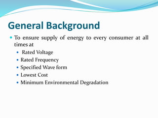
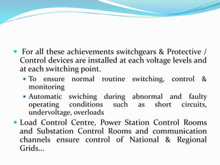
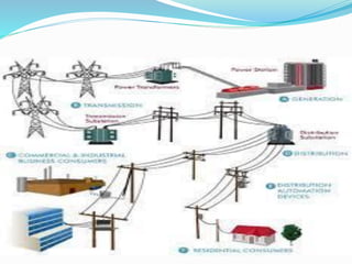
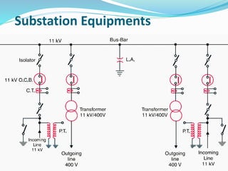
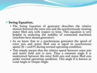
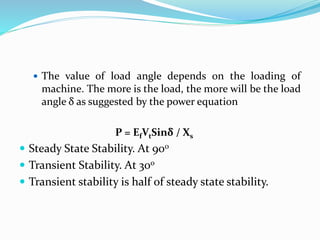
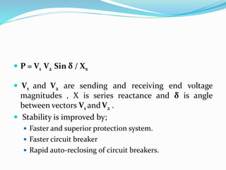

This document provides an overview of switchgears and protective devices used in power systems. It discusses substations, faults and abnormal conditions, fault calculations, the fault clearing process, protective relaying, and power system stability. Protective devices like circuit breakers, fuses, and relays are installed at different voltage levels and switching points to ensure reliable power supply and isolate faults. Substations are used to change voltage levels and switch equipment in and out of the system. Faults can occur due to insulation failures, breaks, or mechanical issues and their severity is estimated through fault current calculations. Relays detect faults and signal circuit breakers to clear the fault and restore the system. Stability is maintained by keeping the rotor and st


![See4423 chapter1 introduction[1]](https://cdn.slidesharecdn.com/ss_thumbnails/see4423chapter1introduction1-110307213255-phpapp01-thumbnail.jpg?width=640&height=640&fit=bounds)


