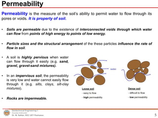
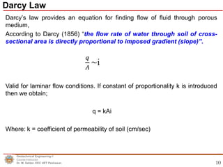
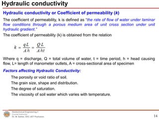
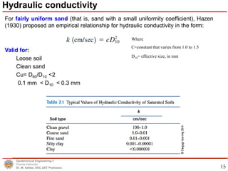
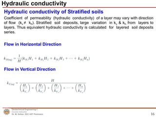
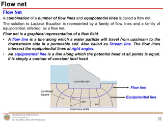
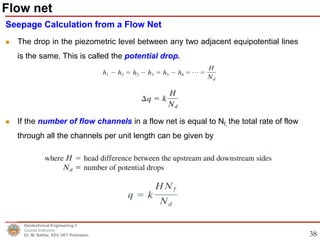
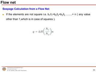
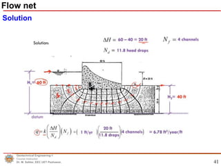
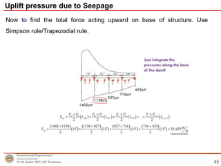
1
Permeability and Seepage
Dr. Muhammad Safdar, PhD. (Professional Geotechnical Engineer)
Assistant Professor, Earthquake Engineering Center,
Department of Civil Engineering,
UET Peshawar, KP, Pakistan.
E-mail: drsafdar@uetpeshawar.edu.pk
CE-331: Geotechnical Engineering-I
.
Lecture-7
Lecture Contents
Geotechnical Engineering-1
Course Instructor
Dr. M. Safdar, EEC UET Peshawar.
A. Permeability
– Permeability
– Scope of Permeability in Geotechnical Engineering
– Darcy’s Law
– Hydraulic Conductivity of Soil
– Hydraulic Conductivity Determination in Laboratory
– Problem 1 & 2
B. Seepage
– Seepage
– Laplace Equation for two dimensional flow
– Flow nets (Problem-3)
– Uplift pressure due to seepage (Problem-4)
3
4
Part (A) Permeability
Permeability
Geotechnical Engineering-1
Course Instructor
Dr. M. Safdar, EEC UET Peshawar.
5
Permeability is the measure of the soil’s ability to permit water to flow through its
pores or voids. It is property of soil.
• Soils are permeable due to the existence of interconnected voids through which water
can flow from points of high energy to points of low energy.
• Particle sizes and the structural arrangement of the these particles influence the rate of
flow in soil.
Permeability
Geotechnical Engineering-1
Course Instructor
Dr. M. Safdar, EEC UET Peshawar.
• A soil is highly pervious when water
can flow through it easily (e.g. sand,
gravel, gravel-sand mixtures).
• In an impervious soil, the permeability
is very low and water cannot easily flow
through it (e.g. silts, clays, silt-clay
mixtures).
• Rocks are impermeable.
6
 Stability analyses of foundations and foundation excavations coming
in contact with flowing water and/or ground water.
 Stability analyses of seepage through dams and/or embankments.
 Stability analyses of seepage through earth retaining walls.
 Design of drainage systems.
 Water lowering.
 Estimation of well yields and design of tube wells.
Scope of Permeability in Geotechnical Engineering
Geotechnical Engineering-1
Course Instructor
Dr. M. Safdar, EEC UET Peshawar.
7
The total Head (h) causing a water flow is given by Bernoulli’s equation
Geotechnical Engineering-1
Course Instructor
Dr. M. Safdar, EEC UET Peshawar.
Permeability
• U is pore water pressure
and v is velocity.
• 𝛾 = ρ*g
8
The total Head (h) causing a water flow is given by Bernoulli’s equation
In case of water flowing through soil, velocity head can be neglected because the
seepage velocity is small, hence:
The loss of head between two points, A and B, can be given by
Geotechnical Engineering-1
Course Instructor
Dr. M. Safdar, EEC UET Peshawar.
Permeability
9
The head loss, Δh , can be expressed in a non dimensional form
Geotechnical Engineering-1
Course Instructor
Dr. M. Safdar, EEC UET Peshawar.
Permeability
Hydraulic gradient(i) between A and B is the total head loss per unit length
i =
𝒉𝑨−𝒉𝑩
𝑳𝑨𝑩
10
Darcy’s law provides an equation for finding flow of fluid through porous
medium,
According to Darcy (1856) “the flow rate of water through soil of cross-
sectional area is directly proportional to imposed gradient (slope)”.
Valid for laminar flow conditions. If constant of proportionality k is introduced
then we obtain;
q = kAi
Where: k = coefficient of permeability of soil (cm/sec)
Darcy Law
Geotechnical Engineering-1
Course Instructor
Dr. M. Safdar, EEC UET Peshawar.
11
 Darcy velocity is a fictitious velocity since it assumes that flow
occurs across the entire cross-section of the soil sample.
 Flow actually takes place only through interconnected pore
channels.
 Discharge velocity < Seepage velocity
Fig 1
Geotechnical Engineering-1
Course Instructor
Dr. M. Safdar, EEC UET Peshawar.
Darcy Law
12
Refer to Fig 1
v = n.vs (n = porosity, n < 100%)
Geotechnical Engineering-1
Course Instructor
Dr. M. Safdar, EEC UET Peshawar.
Darcy Law
13
Assumptions
The following assumptions are made in Darcy’s law;
• The soil is saturated.
• The flow through soil is laminar.
• The flow is continuous and steady.
• The total cross sectional area of soil mass is considered.
• In fine grained soils voids are very small and flow is necessarily
laminar.
• In fractured rock, stones, gravels, and very coarse sands, turbulent
flow conditions may exist.
Geotechnical Engineering-1
Course Instructor
Dr. M. Safdar, EEC UET Peshawar.
Darcy Law
14
Hydraulic conductivity or Coefficient of permeability (k)
The coefficient of permeability, k is defined as “the rate of flow of water under laminar
flow conditions through a porous medium area of unit cross section under unit
hydraulic gradient.”
The coefficient of permeability (k) is obtained from the relation
Where q = discharge, Q = total volume of water, t = time period, h = head causing
flow, L= length of manometer outlets, A = cross-sectional area of specimen
Factors affecting Hydraulic Conductivity:
The porosity or void ratio of soil.
The grain size, shape and distribution.
The degree of saturation.
The viscosity of soil water which varies with temperature.
Hydraulic conductivity
Geotechnical Engineering-1
Course Instructor
Dr. M. Safdar, EEC UET Peshawar.
15
For fairly uniform sand (that is, sand with a small uniformity coefficient), Hazen
(1930) proposed an empirical relationship for hydraulic conductivity in the form:
Valid for:
Loose soil
Clean sand
Cu= D60/D10 <2
0.1 mm < D10 < 0.3 mm
Where
C=constant that varies from 1.0 to 1.5
D10= effective size, in mm
Geotechnical Engineering-1
Course Instructor
Dr. M. Safdar, EEC UET Peshawar.
Hydraulic conductivity
16
Coefficient of permeability (hydraulic conductivity) of a layer may vary with direction
of flow (kv ≠ kh). Stratified soil deposits, large variation in kv & kh from layers to
layers. Thus equivalent hydraulic conductivity is calculated for layered soil deposits
series.
Flow in Horizontal Direction
Flow in Vertical Direction
Hydraulic conductivity of Stratified soils
Geotechnical Engineering-1
Course Instructor
Dr. M. Safdar, EEC UET Peshawar.
Hydraulic conductivity
17
Geotechnical Engineering-1
Course Instructor
Dr. M. Safdar, EEC UET Peshawar.
Hydraulic conductivity
Flow in Horizontal Direction Flow in Vertical Direction
18
Coefficient of permeability (k) is determined in the laboratory using two
methods.
A. Constant head permeability test for coarse grained soils (sands,
gravels and their mixtures).
B. Falling/Variable head permeability test for fine grained soils (silts,
clays and their mixtures).
Hydraulic Conductivity Determination (Laboratory)
Geotechnical Engineering-1
Course Instructor
Dr. M. Safdar, EEC UET Peshawar.
19
Constant head permeability test for coarse grained soils (sands, gravels and their
mixtures).
Geotechnical Engineering-1
Course Instructor
Dr. M. Safdar, EEC UET Peshawar.
Hydraulic Conductivity Determination (Laboratory)
ASTM D2434
20
Constant head permeability test
Geotechnical Engineering-1
Course Instructor
Dr. M. Safdar, EEC UET Peshawar.
Hydraulic Conductivity Determination (Laboratory)
21
Constant head permeability test
Problem-1:
Let a constant head permeability test was done and following data were obtain;
Q = 100 ml, A = 45 cm2
, h = 25 cm, L = 15 cm, t = 37 hrs
Solution:
Geotechnical Engineering-1
Course Instructor
Dr. M. Safdar, EEC UET Peshawar.
Hydraulic Conductivity Determination (Laboratory)
22
Falling/Variable head permeability test for fine grained soils (silts, clays
and their mixtures).
Geotechnical Engineering-1
Course Instructor
Dr. M. Safdar, EEC UET Peshawar.
Hydraulic Conductivity Determination (Laboratory)
ASTM D5084
23
Falling/Variable head permeability test
Geotechnical Engineering-1
Course Instructor
Dr. M. Safdar, EEC UET Peshawar.
Hydraulic Conductivity Determination (Laboratory)
24
Falling/Variable head permeability test
Problem-2
Hydraulic Conductivity Determination (Laboratory)
Geotechnical Engineering-1
Course Instructor
Dr. M. Safdar, EEC UET Peshawar.
Solution
25
Part (B) Seepage
Geotechnical Engineering-1
Course Instructor
Dr. M. Safdar, EEC UET Peshawar.
26
Flow of water through soils is called seepage. It is a phenomena, while
permeability is property of soil.
• Seepage occurs, when there is difference in water levels on the two sides of the
structure such as seepage into a cofferdam or seepage through earth dam or
embankment.
• Estimate the quantity of seepage and the seepage pressure acting on the
structure.
• The soil permeability is the main parameter required in the calculation of seepage
quantity.
• In many cases the flow of water through soil is not in one direction only, nor is it
uniform over the entire area perpendicular to the flow . In such cases, the ground
water flow is generally calculated by the use of graphs, called as flow nets. The
concept of the flow net is based on Laplace's equation of continuity, which
governs the steady flow condition for a given point in the soil mass.
Seepage
Geotechnical Engineering-1
Course Instructor
Dr. M. Safdar, EEC UET Peshawar.
27
Seepage
Seepage
Geotechnical Engineering-1
Course Instructor
Dr. M. Safdar, EEC UET Peshawar.
28
To derive the Laplace differential equation of continuity, let us consider a single row of
sheet piles that have been driven into a permeable soil layer, as shown in Figure 1. The
row of sheet piles is assumed to be impervious. The steady-state flow of water from the
upstream to the downstream side through the permeable layer is a two-dimensional flow.
For flow at a point A, we consider an elemental soil block. The block has dimensions dx, dy,
and dz (length dy is perpendicular to the plane of the paper); it is shown in an enlarged
scale in Figure 2.
Geotechnical Engineering-1
Course Instructor
Dr. M. Safdar, EEC UET Peshawar.
Laplace Equation for two dimensional flow
Figure 1
Figure 2
29
The rates of outflow from the block in the horizontal and vertical directions are,
respectively,
• Water is incompressible and no volume change in the soil mass.
• Total rate of inflow should equal the total rate of outflow
Geotechnical Engineering-1
Course Instructor
Dr. M. Safdar, EEC UET Peshawar.
Laplace Equation for two dimensional flow
30
From Darcy Law, the discharge velocities can be expressed as;
Thus from the above equations we can write as;
If the soil is isotropic with respect to the hydraulic conductivity that is, kx = kz
Geotechnical Engineering-1
Course Instructor
Dr. M. Safdar, EEC UET Peshawar.
Laplace Equation for two dimensional flow
Assumptions in deriving laplace equation for two dimensional flow:
1.The flow is two-dimensional.
2. The flow is steady and laminar.
3. Water and the soil are incompressible.
4. The soil mass is homogeneous and isotropic.
5. The soil is fully saturated and Darcy’s law is valid.
 Consider two solution techniques for Laplace’s equation. One is an
approximate method called flow net sketching, the other is the finite difference
technique.
 The flow net sketching technique is simple and flexible and conveys a picture of
the flow regime.
31
Geotechnical Engineering-1
Course Instructor
Dr. M. Safdar, EEC UET Peshawar.
Laplace Equation for two dimensional flow
32
Flow Net
A combination of a number of flow lines and equipotential lines is called a flow net.
The solution to Laplace Equation is represented by a family of flow lines and a family of
equipotential, referred as a flow net.
Flow net is a graphical representation of a flow field.
• A flow line is a line along which a water particle will travel from upstream to the
downstream side in a permeable soil. Also called as Stream line. The flow lines
intersect the equipotential lines at right angles.
• An equipotential line is a line along which the potential head at all points is equal.
It is simply a contour of constant total head
Geotechnical Engineering-1
Course Instructor
Dr. M. Safdar, EEC UET Peshawar.
Flow net
Flow line
Equipotential line
33
Flow Net Construction
Flow nets are constructed for the calculation of groundwater flow and the
evaluation of heads in the media. To complete the graphic construction of a flow net,
a flow net must meet the following criteria
(1) The boundary conditions must be satisfied, which are (see figure at next slide)
Condition 1: The upstream and downstream surfaces of the permeable layer (lines ab
and de) are equipotential lines.
Condition 2: Because ab and de are equipotential lines, all the flow lines intersect
them at right angles.
Condition 3: The boundary of the impervious layer that is, line fg—is a flow line and
so is the surface of the impervious sheet pile, line acd..
Condition 4: The equipotential lines intersect acd and fg at right angles.
Geotechnical Engineering-1
Course Instructor
Dr. M. Safdar, EEC UET Peshawar.
Flow net
34
Geotechnical Engineering-1
Course Instructor
Dr. M. Safdar, EEC UET Peshawar.
Flow net
Flow Net Construction
35
Flow Net Construction
(2) Flow lines must intersect equipotential lines at right angles.
(3) The area between flow lines and equipotential lines must be curvilinear
squares.
(4) The quantity of flow through each flow channel is constant.
(5) The head loss between each consecutive equipotential line is constant.
(6) Flow lines cannot intersect each other.
(7) Equipotential lines cannot intersect each other.
Geotechnical Engineering-1
Course Instructor
Dr. M. Safdar, EEC UET Peshawar.
Flow net
36
Flow Net Construction
Flow of water under dams
Geotechnical Engineering-1
Course Instructor
Dr. M. Safdar, EEC UET Peshawar.
Flow net
37
Seepage Calculation from a Flow Net
 In any flow net, the strip between any two adjacent flow lines is called a flow
channel.
 Because there is no flow across the flow lines, thus
Geotechnical Engineering-1
Course Instructor
Dr. M. Safdar, EEC UET Peshawar.
Flow net
38
Seepage Calculation from a Flow Net
 The drop in the piezometric level between any two adjacent equipotential lines
is the same. This is called the potential drop.
 If the number of flow channels in a flow net is equal to Nf, the total rate of flow
through all the channels per unit length can be given by
Geotechnical Engineering-1
Course Instructor
Dr. M. Safdar, EEC UET Peshawar.
Flow net
39
Seepage Calculation from a Flow Net
 If the elements are not square i.e. b1/l1=b2/l2=b3/l3 …….= n ( any value
other than 1,which is in case of squares ).
Geotechnical Engineering-1
Course Instructor
Dr. M. Safdar, EEC UET Peshawar.
Flow net
40
Problem-3
Geotechnical Engineering-1
Course Instructor
Dr. M. Safdar, EEC UET Peshawar.
Flow net
41
Geotechnical Engineering-1
Course Instructor
Dr. M. Safdar, EEC UET Peshawar.
Flow net
Solution
42
Pressure at any point, X, at the base of structure under which seepage occurs is
given by :
Since the total head at X , 𝐻𝑥 = pressure head + elevation head
𝐻𝑥 = 𝑃𝑥/ γ𝑤 + 𝑍𝑥
Re-arranging for 𝑃𝑥,
𝑃𝑥 = γ𝑤 𝐻𝑥 − 𝑍𝑥
Where Hx=head at point x
Zx= Height of point x from datum or impervious layer
Hx= HB- Head loss/drop . (No of drops to Point x)
Δh=ΔH/nd
Uplift pressure due to Seepage
Bernoulli’s equation =
Geotechnical Engineering-1
Course Instructor
Dr. M. Safdar, EEC UET Peshawar.
43
Problem-4
Find the pressure at Point B and at base of the structure given in the
previous example.
Geotechnical Engineering-1
Course Instructor
Dr. M. Safdar, EEC UET Peshawar.
Uplift pressure due to Seepage
44
Solution:
Geotechnical Engineering-1
Course Instructor
Dr. M. Safdar, EEC UET Peshawar.
Uplift pressure due to Seepage
45
Now to find the total force acting upward on base of structure. Use
Simpson rule/Trapezodial rule.
Geotechnical Engineering-1
Course Instructor
Dr. M. Safdar, EEC UET Peshawar.
Uplift pressure due to Seepage
Geotechnical Engineering-1
Course Instructor
Dr. M. Safdar, EEC UET Peshawar.
Thank You
Any Question(s) ?
46

Lecture 07 permeability and seepage (11-dec-2021)

  • 1.
  • 2.
    Permeability and Seepage Dr.Muhammad Safdar, PhD. (Professional Geotechnical Engineer) Assistant Professor, Earthquake Engineering Center, Department of Civil Engineering, UET Peshawar, KP, Pakistan. E-mail: drsafdar@uetpeshawar.edu.pk CE-331: Geotechnical Engineering-I . Lecture-7
  • 3.
    Lecture Contents Geotechnical Engineering-1 CourseInstructor Dr. M. Safdar, EEC UET Peshawar. A. Permeability – Permeability – Scope of Permeability in Geotechnical Engineering – Darcy’s Law – Hydraulic Conductivity of Soil – Hydraulic Conductivity Determination in Laboratory – Problem 1 & 2 B. Seepage – Seepage – Laplace Equation for two dimensional flow – Flow nets (Problem-3) – Uplift pressure due to seepage (Problem-4) 3
  • 4.
    4 Part (A) Permeability Permeability GeotechnicalEngineering-1 Course Instructor Dr. M. Safdar, EEC UET Peshawar.
  • 5.
    5 Permeability is themeasure of the soil’s ability to permit water to flow through its pores or voids. It is property of soil. • Soils are permeable due to the existence of interconnected voids through which water can flow from points of high energy to points of low energy. • Particle sizes and the structural arrangement of the these particles influence the rate of flow in soil. Permeability Geotechnical Engineering-1 Course Instructor Dr. M. Safdar, EEC UET Peshawar. • A soil is highly pervious when water can flow through it easily (e.g. sand, gravel, gravel-sand mixtures). • In an impervious soil, the permeability is very low and water cannot easily flow through it (e.g. silts, clays, silt-clay mixtures). • Rocks are impermeable.
  • 6.
    6  Stability analysesof foundations and foundation excavations coming in contact with flowing water and/or ground water.  Stability analyses of seepage through dams and/or embankments.  Stability analyses of seepage through earth retaining walls.  Design of drainage systems.  Water lowering.  Estimation of well yields and design of tube wells. Scope of Permeability in Geotechnical Engineering Geotechnical Engineering-1 Course Instructor Dr. M. Safdar, EEC UET Peshawar.
  • 7.
    7 The total Head(h) causing a water flow is given by Bernoulli’s equation Geotechnical Engineering-1 Course Instructor Dr. M. Safdar, EEC UET Peshawar. Permeability • U is pore water pressure and v is velocity. • 𝛾 = ρ*g
  • 8.
    8 The total Head(h) causing a water flow is given by Bernoulli’s equation In case of water flowing through soil, velocity head can be neglected because the seepage velocity is small, hence: The loss of head between two points, A and B, can be given by Geotechnical Engineering-1 Course Instructor Dr. M. Safdar, EEC UET Peshawar. Permeability
  • 9.
    9 The head loss,Δh , can be expressed in a non dimensional form Geotechnical Engineering-1 Course Instructor Dr. M. Safdar, EEC UET Peshawar. Permeability Hydraulic gradient(i) between A and B is the total head loss per unit length i = 𝒉𝑨−𝒉𝑩 𝑳𝑨𝑩
  • 10.
    10 Darcy’s law providesan equation for finding flow of fluid through porous medium, According to Darcy (1856) “the flow rate of water through soil of cross- sectional area is directly proportional to imposed gradient (slope)”. Valid for laminar flow conditions. If constant of proportionality k is introduced then we obtain; q = kAi Where: k = coefficient of permeability of soil (cm/sec) Darcy Law Geotechnical Engineering-1 Course Instructor Dr. M. Safdar, EEC UET Peshawar.
  • 11.
    11  Darcy velocityis a fictitious velocity since it assumes that flow occurs across the entire cross-section of the soil sample.  Flow actually takes place only through interconnected pore channels.  Discharge velocity < Seepage velocity Fig 1 Geotechnical Engineering-1 Course Instructor Dr. M. Safdar, EEC UET Peshawar. Darcy Law
  • 12.
    12 Refer to Fig1 v = n.vs (n = porosity, n < 100%) Geotechnical Engineering-1 Course Instructor Dr. M. Safdar, EEC UET Peshawar. Darcy Law
  • 13.
    13 Assumptions The following assumptionsare made in Darcy’s law; • The soil is saturated. • The flow through soil is laminar. • The flow is continuous and steady. • The total cross sectional area of soil mass is considered. • In fine grained soils voids are very small and flow is necessarily laminar. • In fractured rock, stones, gravels, and very coarse sands, turbulent flow conditions may exist. Geotechnical Engineering-1 Course Instructor Dr. M. Safdar, EEC UET Peshawar. Darcy Law
  • 14.
    14 Hydraulic conductivity orCoefficient of permeability (k) The coefficient of permeability, k is defined as “the rate of flow of water under laminar flow conditions through a porous medium area of unit cross section under unit hydraulic gradient.” The coefficient of permeability (k) is obtained from the relation Where q = discharge, Q = total volume of water, t = time period, h = head causing flow, L= length of manometer outlets, A = cross-sectional area of specimen Factors affecting Hydraulic Conductivity: The porosity or void ratio of soil. The grain size, shape and distribution. The degree of saturation. The viscosity of soil water which varies with temperature. Hydraulic conductivity Geotechnical Engineering-1 Course Instructor Dr. M. Safdar, EEC UET Peshawar.
  • 15.
    15 For fairly uniformsand (that is, sand with a small uniformity coefficient), Hazen (1930) proposed an empirical relationship for hydraulic conductivity in the form: Valid for: Loose soil Clean sand Cu= D60/D10 <2 0.1 mm < D10 < 0.3 mm Where C=constant that varies from 1.0 to 1.5 D10= effective size, in mm Geotechnical Engineering-1 Course Instructor Dr. M. Safdar, EEC UET Peshawar. Hydraulic conductivity
  • 16.
    16 Coefficient of permeability(hydraulic conductivity) of a layer may vary with direction of flow (kv ≠ kh). Stratified soil deposits, large variation in kv & kh from layers to layers. Thus equivalent hydraulic conductivity is calculated for layered soil deposits series. Flow in Horizontal Direction Flow in Vertical Direction Hydraulic conductivity of Stratified soils Geotechnical Engineering-1 Course Instructor Dr. M. Safdar, EEC UET Peshawar. Hydraulic conductivity
  • 17.
    17 Geotechnical Engineering-1 Course Instructor Dr.M. Safdar, EEC UET Peshawar. Hydraulic conductivity Flow in Horizontal Direction Flow in Vertical Direction
  • 18.
    18 Coefficient of permeability(k) is determined in the laboratory using two methods. A. Constant head permeability test for coarse grained soils (sands, gravels and their mixtures). B. Falling/Variable head permeability test for fine grained soils (silts, clays and their mixtures). Hydraulic Conductivity Determination (Laboratory) Geotechnical Engineering-1 Course Instructor Dr. M. Safdar, EEC UET Peshawar.
  • 19.
    19 Constant head permeabilitytest for coarse grained soils (sands, gravels and their mixtures). Geotechnical Engineering-1 Course Instructor Dr. M. Safdar, EEC UET Peshawar. Hydraulic Conductivity Determination (Laboratory) ASTM D2434
  • 20.
    20 Constant head permeabilitytest Geotechnical Engineering-1 Course Instructor Dr. M. Safdar, EEC UET Peshawar. Hydraulic Conductivity Determination (Laboratory)
  • 21.
    21 Constant head permeabilitytest Problem-1: Let a constant head permeability test was done and following data were obtain; Q = 100 ml, A = 45 cm2 , h = 25 cm, L = 15 cm, t = 37 hrs Solution: Geotechnical Engineering-1 Course Instructor Dr. M. Safdar, EEC UET Peshawar. Hydraulic Conductivity Determination (Laboratory)
  • 22.
    22 Falling/Variable head permeabilitytest for fine grained soils (silts, clays and their mixtures). Geotechnical Engineering-1 Course Instructor Dr. M. Safdar, EEC UET Peshawar. Hydraulic Conductivity Determination (Laboratory) ASTM D5084
  • 23.
    23 Falling/Variable head permeabilitytest Geotechnical Engineering-1 Course Instructor Dr. M. Safdar, EEC UET Peshawar. Hydraulic Conductivity Determination (Laboratory)
  • 24.
    24 Falling/Variable head permeabilitytest Problem-2 Hydraulic Conductivity Determination (Laboratory) Geotechnical Engineering-1 Course Instructor Dr. M. Safdar, EEC UET Peshawar. Solution
  • 25.
    25 Part (B) Seepage GeotechnicalEngineering-1 Course Instructor Dr. M. Safdar, EEC UET Peshawar.
  • 26.
    26 Flow of waterthrough soils is called seepage. It is a phenomena, while permeability is property of soil. • Seepage occurs, when there is difference in water levels on the two sides of the structure such as seepage into a cofferdam or seepage through earth dam or embankment. • Estimate the quantity of seepage and the seepage pressure acting on the structure. • The soil permeability is the main parameter required in the calculation of seepage quantity. • In many cases the flow of water through soil is not in one direction only, nor is it uniform over the entire area perpendicular to the flow . In such cases, the ground water flow is generally calculated by the use of graphs, called as flow nets. The concept of the flow net is based on Laplace's equation of continuity, which governs the steady flow condition for a given point in the soil mass. Seepage Geotechnical Engineering-1 Course Instructor Dr. M. Safdar, EEC UET Peshawar.
  • 27.
  • 28.
    28 To derive theLaplace differential equation of continuity, let us consider a single row of sheet piles that have been driven into a permeable soil layer, as shown in Figure 1. The row of sheet piles is assumed to be impervious. The steady-state flow of water from the upstream to the downstream side through the permeable layer is a two-dimensional flow. For flow at a point A, we consider an elemental soil block. The block has dimensions dx, dy, and dz (length dy is perpendicular to the plane of the paper); it is shown in an enlarged scale in Figure 2. Geotechnical Engineering-1 Course Instructor Dr. M. Safdar, EEC UET Peshawar. Laplace Equation for two dimensional flow Figure 1 Figure 2
  • 29.
    29 The rates ofoutflow from the block in the horizontal and vertical directions are, respectively, • Water is incompressible and no volume change in the soil mass. • Total rate of inflow should equal the total rate of outflow Geotechnical Engineering-1 Course Instructor Dr. M. Safdar, EEC UET Peshawar. Laplace Equation for two dimensional flow
  • 30.
    30 From Darcy Law,the discharge velocities can be expressed as; Thus from the above equations we can write as; If the soil is isotropic with respect to the hydraulic conductivity that is, kx = kz Geotechnical Engineering-1 Course Instructor Dr. M. Safdar, EEC UET Peshawar. Laplace Equation for two dimensional flow
  • 31.
    Assumptions in derivinglaplace equation for two dimensional flow: 1.The flow is two-dimensional. 2. The flow is steady and laminar. 3. Water and the soil are incompressible. 4. The soil mass is homogeneous and isotropic. 5. The soil is fully saturated and Darcy’s law is valid.  Consider two solution techniques for Laplace’s equation. One is an approximate method called flow net sketching, the other is the finite difference technique.  The flow net sketching technique is simple and flexible and conveys a picture of the flow regime. 31 Geotechnical Engineering-1 Course Instructor Dr. M. Safdar, EEC UET Peshawar. Laplace Equation for two dimensional flow
  • 32.
    32 Flow Net A combinationof a number of flow lines and equipotential lines is called a flow net. The solution to Laplace Equation is represented by a family of flow lines and a family of equipotential, referred as a flow net. Flow net is a graphical representation of a flow field. • A flow line is a line along which a water particle will travel from upstream to the downstream side in a permeable soil. Also called as Stream line. The flow lines intersect the equipotential lines at right angles. • An equipotential line is a line along which the potential head at all points is equal. It is simply a contour of constant total head Geotechnical Engineering-1 Course Instructor Dr. M. Safdar, EEC UET Peshawar. Flow net Flow line Equipotential line
  • 33.
    33 Flow Net Construction Flownets are constructed for the calculation of groundwater flow and the evaluation of heads in the media. To complete the graphic construction of a flow net, a flow net must meet the following criteria (1) The boundary conditions must be satisfied, which are (see figure at next slide) Condition 1: The upstream and downstream surfaces of the permeable layer (lines ab and de) are equipotential lines. Condition 2: Because ab and de are equipotential lines, all the flow lines intersect them at right angles. Condition 3: The boundary of the impervious layer that is, line fg—is a flow line and so is the surface of the impervious sheet pile, line acd.. Condition 4: The equipotential lines intersect acd and fg at right angles. Geotechnical Engineering-1 Course Instructor Dr. M. Safdar, EEC UET Peshawar. Flow net
  • 34.
    34 Geotechnical Engineering-1 Course Instructor Dr.M. Safdar, EEC UET Peshawar. Flow net Flow Net Construction
  • 35.
    35 Flow Net Construction (2)Flow lines must intersect equipotential lines at right angles. (3) The area between flow lines and equipotential lines must be curvilinear squares. (4) The quantity of flow through each flow channel is constant. (5) The head loss between each consecutive equipotential line is constant. (6) Flow lines cannot intersect each other. (7) Equipotential lines cannot intersect each other. Geotechnical Engineering-1 Course Instructor Dr. M. Safdar, EEC UET Peshawar. Flow net
  • 36.
    36 Flow Net Construction Flowof water under dams Geotechnical Engineering-1 Course Instructor Dr. M. Safdar, EEC UET Peshawar. Flow net
  • 37.
    37 Seepage Calculation froma Flow Net  In any flow net, the strip between any two adjacent flow lines is called a flow channel.  Because there is no flow across the flow lines, thus Geotechnical Engineering-1 Course Instructor Dr. M. Safdar, EEC UET Peshawar. Flow net
  • 38.
    38 Seepage Calculation froma Flow Net  The drop in the piezometric level between any two adjacent equipotential lines is the same. This is called the potential drop.  If the number of flow channels in a flow net is equal to Nf, the total rate of flow through all the channels per unit length can be given by Geotechnical Engineering-1 Course Instructor Dr. M. Safdar, EEC UET Peshawar. Flow net
  • 39.
    39 Seepage Calculation froma Flow Net  If the elements are not square i.e. b1/l1=b2/l2=b3/l3 …….= n ( any value other than 1,which is in case of squares ). Geotechnical Engineering-1 Course Instructor Dr. M. Safdar, EEC UET Peshawar. Flow net
  • 40.
  • 41.
    41 Geotechnical Engineering-1 Course Instructor Dr.M. Safdar, EEC UET Peshawar. Flow net Solution
  • 42.
    42 Pressure at anypoint, X, at the base of structure under which seepage occurs is given by : Since the total head at X , 𝐻𝑥 = pressure head + elevation head 𝐻𝑥 = 𝑃𝑥/ γ𝑤 + 𝑍𝑥 Re-arranging for 𝑃𝑥, 𝑃𝑥 = γ𝑤 𝐻𝑥 − 𝑍𝑥 Where Hx=head at point x Zx= Height of point x from datum or impervious layer Hx= HB- Head loss/drop . (No of drops to Point x) Δh=ΔH/nd Uplift pressure due to Seepage Bernoulli’s equation = Geotechnical Engineering-1 Course Instructor Dr. M. Safdar, EEC UET Peshawar.
  • 43.
    43 Problem-4 Find the pressureat Point B and at base of the structure given in the previous example. Geotechnical Engineering-1 Course Instructor Dr. M. Safdar, EEC UET Peshawar. Uplift pressure due to Seepage
  • 44.
    44 Solution: Geotechnical Engineering-1 Course Instructor Dr.M. Safdar, EEC UET Peshawar. Uplift pressure due to Seepage
  • 45.
    45 Now to findthe total force acting upward on base of structure. Use Simpson rule/Trapezodial rule. Geotechnical Engineering-1 Course Instructor Dr. M. Safdar, EEC UET Peshawar. Uplift pressure due to Seepage
  • 46.
    Geotechnical Engineering-1 Course Instructor Dr.M. Safdar, EEC UET Peshawar. Thank You Any Question(s) ? 46