Download as PDF, PPTX
![University of Anbar
College of Engineering
Civil Engineering Department
Iraq-Ramadi
Asst. Prof. Khalid R. Mahmood (PhD.)
220
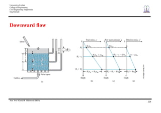
Since as is very small, assume = 0
= /
+ u
Recall the following equation:
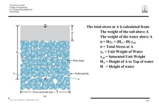
= H w + (HA - H) sat
Now, /
= - u
Substituting: /
= [H w + (HA - H) sat] - HA w
Rearranging: /
= (HA - H)( sat - w) = Hsoil
/
Effective Stress is independent of height of water
In the equation: = /
+ u
/
is the soil skeleton stress
u is the stress in the water, or pore water pressure](https://image.slidesharecdn.com/5-effectivestressconcept-150320010033-conversion-gate01/85/5-effective-stress-concept-6-320.jpg)
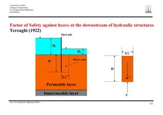
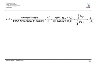
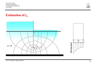
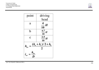
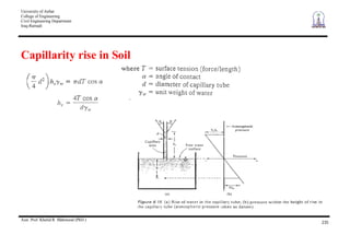
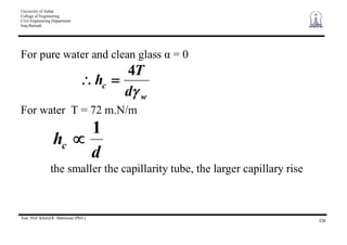
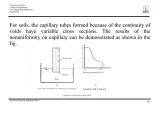
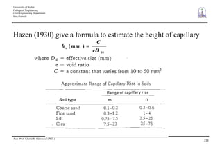
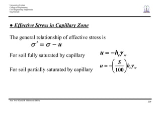
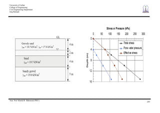
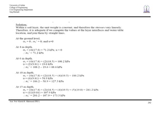
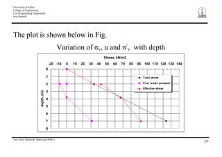

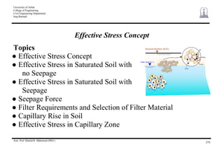
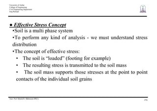
This document is a series of lecture slides from Assistant Professor Khalid R. Mahmood at the University of Anbar in Iraq-Ramadi on the topic of effective stress concepts in soil mechanics. It introduces key concepts such as effective stress, total stress, pore water pressure, and their relationships. It also discusses effective stress in saturated soil with and without seepage, seepage forces, filter requirements, capillary rise in soil, and two example problems calculating stresses with depth.


![Geotechnical Engineering-I [Lec #23: Soil Permeability]](https://cdn.slidesharecdn.com/ss_thumbnails/23-180924141141-thumbnail.jpg?width=640&height=640&fit=bounds)


![Geotechnical Engineering-I [Lec #17: Consolidation]](https://cdn.slidesharecdn.com/ss_thumbnails/17-180924140731-thumbnail.jpg?width=640&height=640&fit=bounds)


![Geotechnical Engineering-II [Lec #28: Finite Slope Stability Analysis]](https://cdn.slidesharecdn.com/ss_thumbnails/28-181125070402-thumbnail.jpg?width=640&height=640&fit=bounds)


![Geotechnical Engineering-II [Lec #11: Settlement Computation]](https://cdn.slidesharecdn.com/ss_thumbnails/11-181020124840-thumbnail.jpg?width=640&height=640&fit=bounds)

![Geotechnical Engineering-II [Lec #23: Rankine Earth Pressure Theory]](https://cdn.slidesharecdn.com/ss_thumbnails/23-181123050516-thumbnail.jpg?width=640&height=640&fit=bounds)