Download to read offline
![Rajesh K. Devmurari et al. Int. Journal of Engineering Research and Applications www.ijera.com
ISSN: 2248-9622, Vol. 5, Issue 11, (Part - 4) November 2015, pp.20-22
www.ijera.com 21 | P a g e
container’s longitudinal axis. At the other end of the
section water level is maintained at H2. Out flow
from the tube is collected in the graduated jar. [as
shown in the figure].
(Schematic diagram of one dimensional flow)
apparatus
Thus, flow shall take between the L-section due
to potential head difference. The potential difference
that causes flow is the difference between total
potential ( or total head) which is the sum of the
pressure head, the elevation head and the velocity
head. For flow through sand, silt and clays the
velocity head is very small and can be neglected.
Thus total head is equal to the sum of the pressure
and the elevation head and is called Piezometer head.
This can be determined by just inserting two
piezometer at the ends and measure the head
difference. The measured difference is say ∆H. As
shown in the figure, flow occurs through c/s ‘A’ and
through the length L. The flow occurring per unit
time can be measured in graduated jar. We may
change any of the three variable ∆H,L and A and
conduct the experiment.
From this experiment we can see that,
If area of c/s and head is doubled, the flow
occurring is double.
If the length is doubled the flow occurring is
halved.
The head causing flow is lost linearly along the
length of sample.
Now, say water collected in jar is Q, then it is
directly proportional to the head causing flow and of
c/s of the soil sample but is inversely proportional to
the length of the soil sample, or,
Q ∝
∆H
L
A …………………………………….. 2.1
The constant changed when soil sample was
changed. Thus it is property of soil & is known as
permeability ‘k’.
Q = k
∆H
L
A………………………………….…2.2
Dimensionally,
L3
T
=
L
T
L
L
L2
=
L3
T
Where L is length and T is time.
Equation 2.2 can be written as,
Q = kiA……………………………………….…2.3
Where i=
∆H
L
. The hydraulic gradient, is the head lost
per unit distance and it is a dimensionless parameter.
Dividing both sides by Ae.g we get,
𝑄
𝐴
= k i=v
Where v is the superficial velocity of flow. It is not
actual velocity of the flow, through the pores in the
cross-section A and not A itself.
The permeability of a soil, than, can be viewed
as the superficial velocity under a hydraulic gradient
of 1.0. Thus we can also make an estimate of the
average actual velocity of water, known as seepage
velocity,Vs. Volume of soil multiplied by its porosity
is the volume of pores. The cross-sectional area A
multiplied by the porosity is thus the cross-sectional
area of the pores.
Vs=
𝑄
𝐴 𝑛
=
𝑣
𝑛
Darcy’s law has been working up til the flow is
laminar and almost flow of water underground is
generally laminar.
How to measure permeability?
2.2 Constant Head Permeameter
As shown in the figure the same set-up can be
used to measure permeability of soils. ∆H,L, A and Q
need to be measured. By Darcy’s law the
permeability can be calculated from
K=
Q
A
L
∆H
The apparatus shown in the figure is known as
‘”Constant Head Permeameter”, because the head
∆H , is kept constant throughout the experiment. The
flow Q is measured by calculating volume in Jar and
a stop-water. To measure the flow, by this method it
is necessary to have the flow considerable, hence this
method is useful only for sand and siltysand. As the
flow is only in one direction.i.e. X-direction i.e. it is
one-dimensional steady state flow through
homogeneous material.
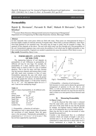
2.3 Falling Head Permeameter:-
We saw in above section, that we had constant
head and is possible for the soils of high
permeability. But to determine the permeability of](https://image.slidesharecdn.com/e511042022-151127045311-lva1-app6891/85/Permeability-2-320.jpg)
![Rajesh K. Devmurari et al. Int. Journal of Engineering Research and Applications www.ijera.com
ISSN: 2248-9622, Vol. 5, Issue 11, (Part - 4) November 2015, pp.20-22
www.ijera.com 22 | P a g e
soil with low permeability such as silts, silty clays
and clays falling head permeability method is used.
The apparatus are shown in fig..
Fig.(2) - Falling Head Permeameter
The flow is measured very precisely by
measuring in a vertical pipe, for a long duration of
time. As seen in the figure when the flow takes place,
there is fall in the head in the vertical pipe. (fig 2)
According to Darcy, for head change causing the
flow, at any time t.
Q=k
h
L
A
For time dt, water level drops to dh,
Q=−a
dh
dt
= k
h
L
A
Or
−
dh
h
=
kA
La
dt
Integrating over the limits of initial and final
condition of head causing flow and time,
hf
dh
h
=
hf
hi
kA
La
dt
tf
ti
ln
hi
hf
=
kA
La
tf − ti
k=
La
A
ln
hi
hf
tf−ti
By the above apparatus and arrangement we can
measure permeability of soil in laboratory.
References
[1.] Irrigation Water Resources and water power
engineering P N Modi
[2.] Irrigation and water power engineering B C
Punamia
[3.] Geotechnical Engineering by Shashi K
Gulhati, Manoj Datta Google scholar
NPTEL Lectures Google.](https://image.slidesharecdn.com/e511042022-151127045311-lva1-app6891/85/Permeability-3-320.jpg)

The document discusses the concept of soil permeability, which is defined as the ease with which water flows through soil, influenced by factors such as soil type, void ratio, and soil structure. It explains Darcy's law for measuring permeability through different methods including constant and falling head permeameters, detailing how water movement can be quantitatively assessed. The research highlights the significant variation in permeability across different soil types, emphasizing the importance of evaluating soil characteristics for engineering applications.


![Geotechnical Engineering-I [Lec #23: Soil Permeability]](https://cdn.slidesharecdn.com/ss_thumbnails/23-180924141141-thumbnail.jpg?width=640&height=640&fit=bounds)


![Geotechnical Engineering-I [Lec #25: In-Situ Permeability]](https://cdn.slidesharecdn.com/ss_thumbnails/25-180924141200-thumbnail.jpg?width=640&height=640&fit=bounds)


![Geotechnical Engineering-I [Lec #8: Hydrometer Analysis]](https://cdn.slidesharecdn.com/ss_thumbnails/8-180923180849-thumbnail.jpg?width=640&height=640&fit=bounds)

![Geotechnical Engineering-I [Lec #27: Flow Nets]](https://cdn.slidesharecdn.com/ss_thumbnails/27-180924141458-thumbnail.jpg?width=640&height=640&fit=bounds)


