Downloaded 202 times


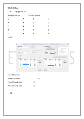
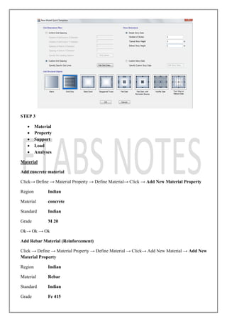


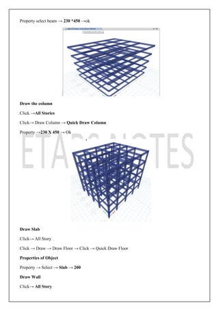


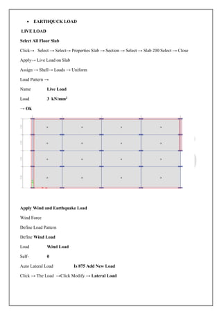
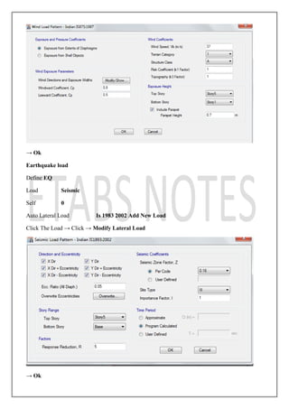
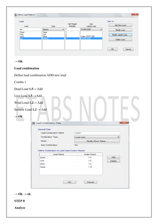
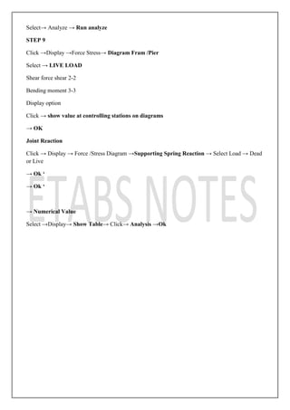

This document provides instructions for analyzing and designing a G+4 multistory building using ETABS. It includes steps to model the building with beams, columns, slabs and walls. Materials are defined for concrete, rebar and masonry. Section properties are created for beams, columns and slabs. The building grid is laid out and elements are drawn. Supports are assigned and loads including dead, live, wind and earthquake are applied. Load combinations are defined and an analysis is run to obtain shear and moment diagrams and joint reactions.


![Attack surfaces and attack tress[inform]](https://cdn.slidesharecdn.com/ss_thumbnails/lecture03-260108015941-a4dee53b-thumbnail.jpg?width=640&height=640&fit=bounds)