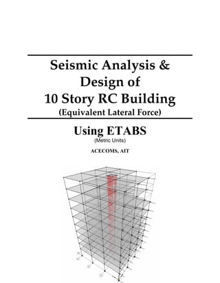
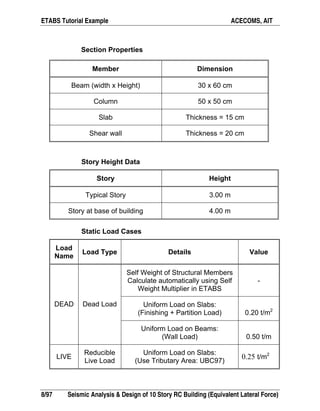
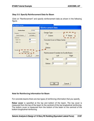
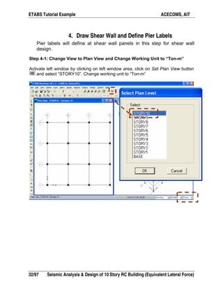
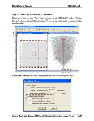
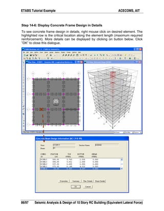
The document provides step-by-step instructions for modeling, analyzing, and designing a 10-story reinforced concrete building using ETABS. It defines the material properties, section properties, load cases, and equivalent lateral force parameters. The steps include starting a new model, defining section properties for beams, columns, slabs, and walls, assigning sections, defining load cases, and specifying the analysis and design procedures.
The Manual explains the concept of transferring the load from the super structure up to the soil throughout Piles, which has a capacity of (End bearing, and Skin friction). It illustrates the steps needed to produce a full and safe foundation for your Super Structure.
Tower design using Dynamic analysis method is now became easier than ever with this simple and effective PDF manual. Starting from modeling, defining till computing results based on Dynamic Analysis you can build the tower of your dream.
Engineering is fun and so does this PDF !
The aim of this manual is to give the design application of the basic requirements of EC8 for new concrete and steel buildings using ETABS. This book can be used by users of ETABS modeler. Is not cover all the steps that you have to carry during designing model using ETABS but is a good manual for those who using Eurocodes.
This publication provides a concise compilation of selected rules in the Eurocode 8, together with relevant Cyprus National Annex, that relate to the design of common forms of concrete building structure in the South Europe. It id offers a detail view of the design of steel framed buildings to the structural Eurocodes and includes a set of worked examples showing the design of structural elements with using software (CSI ETABS). It is intended to be of particular to the people who want to become acquainted with design to the Eurocodes. Rules from EN 1998-1-1 for global analysis, type of analysis and verification checks are presented. Detail design rules for steel composite beam, steel column, steel bracing and composite slab with steel sheeting from EN 1998-1-1, EN1993-1-1 and EN1994-1-1 are presented. This guide covers the design of orthodox members in steel frames. It does not cover design rules for regularities. Certain practical limitations are given to the scope.
Modelling Building Frame with STAAD.Pro & ETABS - Rahul LeslieRahul Leslie
A basic tutorial to learn the concepts of modelling RC building in an Analysis/Design package -- STAAD.Pro & ETABS are in focus here, but concepts are applicable for any package. Good for novice in structural designing, and also B.Tech / BE / BSc (Engg) / BS students wising to do 'design of multi-storied RC building' as their final year project.
Part-II: Seismic Analysis/Design of Multi-storied RC Buildings using STAAD.Pr...Rahul Leslie
For novice, please continue from "Modelling Building Frame with STAAD.Pro & ETABS" (http://www.slideshare.net/rahulleslie/modelling-building-frame-with-staadpro-etabs-rahul-leslie).
This is a presentation covering almost all aspects of Seismic analysis & design of Multi-storied RC Structures using the Indian code IS:1893-2016 (New edition), with references to IS:13920-2015 (Code for ductile detailing) & IS:16700-2017 (code for design of tall buildings) where relevant; following for each aspect of the code, (1) The clause/formula (2) It's explanation/theory (3) How it is/can be implemented in the software packages of (i) STAAD.Pro and (ii) ETABS
This is the latest edition of the earlier slides based on IS:1893-2002 which this one supersedes. This is Part-II of a two part series.
Part-I: Seismic Analysis/Design of Multi-storied RC Buildings using STAAD.Pro...Rahul Leslie
For novice, please continue from "Modelling Building Frame with STAAD.Pro & ETABS" (http://www.slideshare.net/rahulleslie/modelling-building-frame-with-staadpro-etabs-rahul-leslie).
This is a presentation covering almost all aspects of Seismic analysis & design of Multi-storied RC Structures using the Indian code IS:1893-2016 (New edition), with references to IS:13920-2015 (Code for ductile detailing) & IS:16700-2017 (code for design of tall buildings) where relevant; following for each aspect of the code, (1) The clause/formula (2) It's explanation/theory (3) How it is/can be implemented in the software packages of (i) STAAD.Pro and (ii) ETABS
This is the latest edition of the earlier slides based on IS:1893-2002 which this one supersedes. This is Part-I of a two part series.
Book for Beginners, RCC Design by ETABSYousuf Dinar
Advancement of softwares is main cause behind comparatively quick and simple
design while avoiding complexity and time consuming manual procedure. However
mistake or mislead could be happened during designing the structures because of not
knowing the proper procedure depending on the situation. Design book based on
manual or hand design is sometimes time consuming and could not be good aids with
softwares as several steps are shorten during finite element modeling. This book may
work as a general learning hand book which bridges the software and the manual
design properly. The writers of this book used linear static analysis under BNBC and
ACI code to generate a six story residential building which could withstand wind load
of 210 kmph and seismic event of that region. The building is assumed to be designed
in Dhaka, Bangladesh under RAJUK rules to get legality of that concern organization.
For easy and explained understanding the book chapters are oriented in 2 parts. Part A
is concern about modeling and analysis which completed in only one chapter. Part B
is organized with 8 chapters. From chapter 1 to 7 the writers designed the model
building and explained with references how to consider during design so that
creativity of readers could not be threated. Chapter 8 is dedicated for estimation. As a
whole the book will help the readers to experience a building construction related all
facts and how to progress in design. Although the volume I is limited to linear static
analysis, upcoming volume will eventually consider dynamic facts to perform
dynamic analysis. Implemented equations are organized in the appendix section for
easy memorizing.
BNBC and other codes are improving and expending day by day, by covering new
and improved information as civil engineering is a vast field to continue the research.
Before designing something or taking decision judge the contemporary codes and
choose data, equations, factors and coefficient from the updated one.
Book for Beginners series is basic learning book of YDAS outlines. Here only
rectangular grid system modeling and a particular model is shown. Round shape grid
is avoided to keep the study simple. No advanced analysis is described and it is kept
simple for beginners. Only two way slab is elaborated with direct design method,
avoiding other procedures. In case of beam, only flexural and shear designs are made.
T- Beam, L- Beam or other shapes are not shown as rectangular beam was enough for
this study. Bi-axial column and foundation design is not shown. During column and
foundation design only pure axial load is considered. Use of interaction diagram is not
shown in manual design. Load centered isolated and combined footing designs are
shown, avoiding eccentric loading conditions. Pile and pile cap design, Mat
foundation design, strap footing design and sand pile concept are not included in this
This document presents an example of analysis design of slab using ETABS. This example examines a simple single story building, which is regular in plan and elevation. It is examining and compares the calculated ultimate moment from ETABS with hand calculation. Moment coefficients were used to calculate the ultimate moment. However it is good practice that such hand analysis methods are used to verify the output of more sophisticated methods.
Also, this document contains simple procedure (step-by-step) of how to design solid slab according to Eurocode 2. The process of designing elements will not be revolutionised as a result of using Eurocode 2.
This publication provides a concise compilation of selected rules in the Eurocode 8, together with relevant Cyprus National Annex, that relate to the design of common forms of concrete building structure in the South Europe. Rules from EN 1998-1-1 for global analysis, regularity criteria, type of analysis and verification checks are presented. Detail design rules for concrete beam, column and shear wall, from EN 1998-1-1 and EN1992-1-1 are presented. This guide covers the design of orthodox members in concrete frames. It does not cover design rules for steel frames. Certain practical limitations are given to the scope.
This publication provides a concise compilation of selected rules in the Eurocode 8 Part 1 & 3, together with relevant Cyprus National Annex, that relate to the seismic design of common forms of concrete building structure in the South Europe. Rules from EN 1998-3 for global analysis, type of analysis and verification checks are presented. Detail design check rules for concrete beam, column and shear wall, from EN 1998-3 are also presented. This guide covers the assessment of orthodox members in concrete frames. It does not cover design rules for steel frames. Certain practical limitations are given to the scope.
Due to time constraints and knowledge, I may not be able to address the whole issues.
Please send me your suggestions for improvement. Anyone interested to share his/her knowledge or willing to contribute either totally a new section about Eurocode 8-3 or within this section is encouraged.
we using lathe bed choose different materials and using creo and ansys we conclude some results that which material is best, also we remove some materials in order to reduce cost and weight.
The International Journal of Engineering & Science is aimed at providing a platform for researchers, engineers, scientists, or educators to publish their original research results, to exchange new ideas, to disseminate information in innovative designs, engineering experiences and technological skills. It is also the Journal's objective to promote engineering and technology education. All papers submitted to the Journal will be blind peer-reviewed. Only original articles will be published.
The papers for publication in The International Journal of Engineering& Science are selected through rigorous peer reviews to ensure originality, timeliness, relevance, and readability.
Cross Section Analysis And Design is a powerful application that can perform a wide range of cross section calculations, including the design of reinforced concrete sections. The given cross sections are built up of one or more geometric entities and can be drawn directly using the versatile featured user interface. The user can also import standard steel sections from a complete shape library according to all major codes (AISC, Australian-New Zealand, BS, Chinese, European, Indian, Aluminum etc.) There are no limitations regarding the shape, materials or loads of a section, since the program can handle any arbitrary cross section under biaxial bending and axial loads. Among its capabilities, Cross Section Analysis And Design can calculate all sectional properties, plot Moment – Curvature and Interaction diagrams, estimate the location of neutral axis under given sets of biaxial loads and plot the corresponding stress – strain diagrams as well as the resulting stress contours. The last -named items can also be calculated by providing the location of the neutral axis plane on the section. Moreover, the program fully complies with all major codes concerning reinforced concrete sections (AASHTO, UBC, AS 3600, IS 456, ACI 318, BS 8110, CSA A233, EC2, NZS 3101 and CP 65). The user can also perform a reinforcement design according to above listed codes, plot the matching interaction diagrams etc., or even check a given reinforcement amount for the specified load cases. The stress – strain curve of concrete, reinforcement and other materials is specified as per the defined Analysis Parameters Sets. Thus calculations can be performed for many design situations, such as Ultimate/Serviceability or custom defined Limit States, with an automatic adjustment of the material properties, safety factors etc. A large material library is also available according to almost all concrete/reinforcement material specifications. Apart from concrete and reinforcement materials, the user can specify custom linear, bilinear, trilinear parabolic or fully general materials.
CADmantra Technologies Pvt. Ltd. is one of the best Cad training company in northern zone in India . which are provided many types of courses in cad field i.e AUTOCAD,SOLIDWORK,CATIA,CRE-O,Uniraphics-NX, CNC, REVIT, STAAD.Pro. And many courses
Contact: www.cadmantra.com
www.cadmantra.blogspot.com
www.cadmantra.wix.com
Four cross-section shapes and seven materials were analyzed to determine the best design for our wing spar. Mathematica code was written to analyze the drag, lift and static loads.
ANALYSIS AND DESIGN OF HIGH RISE BUILDING BY USING ETABSila vamsi krishna
RESULT OF ANALYSIS:
https://www.slideshare.net/ilavamsikrishna/results-of-etabs-on-high-rise-residential-buildings
ANALYSIS AND DESIGN OF BUILDING BY USING STAAD PRO PPT link :
https://www.slideshare.net/ilavamsikrishna/analysis-and-design-of-mutistoried-residential-building-by-using-staad-pro
FOR FULL REPORT:
vamsiila@gmail.com
Similar to Etabs acecoms rcc structure design (20)
Water scarcity is the lack of fresh water resources to meet the standard water demand. There are two type of water scarcity. One is physical. The other is economic water scarcity.
About
Indigenized remote control interface card suitable for MAFI system CCR equipment. Compatible for IDM8000 CCR. Backplane mounted serial and TCP/Ethernet communication module for CCR remote access. IDM 8000 CCR remote control on serial and TCP protocol.
• Remote control: Parallel or serial interface.
• Compatible with MAFI CCR system.
• Compatible with IDM8000 CCR.
• Compatible with Backplane mount serial communication.
• Compatible with commercial and Defence aviation CCR system.
• Remote control system for accessing CCR and allied system over serial or TCP.
• Indigenized local Support/presence in India.
• Easy in configuration using DIP switches.
Technical Specifications
Indigenized remote control interface card suitable for MAFI system CCR equipment. Compatible for IDM8000 CCR. Backplane mounted serial and TCP/Ethernet communication module for CCR remote access. IDM 8000 CCR remote control on serial and TCP protocol.
Key Features
Indigenized remote control interface card suitable for MAFI system CCR equipment. Compatible for IDM8000 CCR. Backplane mounted serial and TCP/Ethernet communication module for CCR remote access. IDM 8000 CCR remote control on serial and TCP protocol.
• Remote control: Parallel or serial interface
• Compatible with MAFI CCR system
• Copatiable with IDM8000 CCR
• Compatible with Backplane mount serial communication.
• Compatible with commercial and Defence aviation CCR system.
• Remote control system for accessing CCR and allied system over serial or TCP.
• Indigenized local Support/presence in India.
Application
• Remote control: Parallel or serial interface.
• Compatible with MAFI CCR system.
• Compatible with IDM8000 CCR.
• Compatible with Backplane mount serial communication.
• Compatible with commercial and Defence aviation CCR system.
• Remote control system for accessing CCR and allied system over serial or TCP.
• Indigenized local Support/presence in India.
• Easy in configuration using DIP switches.
Vaccine management system project report documentation..pdfKamal Acharya
The Division of Vaccine and Immunization is facing increasing difficulty monitoring vaccines and other commodities distribution once they have been distributed from the national stores. With the introduction of new vaccines, more challenges have been anticipated with this additions posing serious threat to the already over strained vaccine supply chain system in Kenya.
Explore the innovative world of trenchless pipe repair with our comprehensive guide, "The Benefits and Techniques of Trenchless Pipe Repair." This document delves into the modern methods of repairing underground pipes without the need for extensive excavation, highlighting the numerous advantages and the latest techniques used in the industry.
Learn about the cost savings, reduced environmental impact, and minimal disruption associated with trenchless technology. Discover detailed explanations of popular techniques such as pipe bursting, cured-in-place pipe (CIPP) lining, and directional drilling. Understand how these methods can be applied to various types of infrastructure, from residential plumbing to large-scale municipal systems.
Ideal for homeowners, contractors, engineers, and anyone interested in modern plumbing solutions, this guide provides valuable insights into why trenchless pipe repair is becoming the preferred choice for pipe rehabilitation. Stay informed about the latest advancements and best practices in the field.
CFD Simulation of By-pass Flow in a HRSG module by R&R Consult.pptxR&R Consult
CFD analysis is incredibly effective at solving mysteries and improving the performance of complex systems!
Here's a great example: At a large natural gas-fired power plant, where they use waste heat to generate steam and energy, they were puzzled that their boiler wasn't producing as much steam as expected.
R&R and Tetra Engineering Group Inc. were asked to solve the issue with reduced steam production.
An inspection had shown that a significant amount of hot flue gas was bypassing the boiler tubes, where the heat was supposed to be transferred.
R&R Consult conducted a CFD analysis, which revealed that 6.3% of the flue gas was bypassing the boiler tubes without transferring heat. The analysis also showed that the flue gas was instead being directed along the sides of the boiler and between the modules that were supposed to capture the heat. This was the cause of the reduced performance.
Based on our results, Tetra Engineering installed covering plates to reduce the bypass flow. This improved the boiler's performance and increased electricity production.
It is always satisfying when we can help solve complex challenges like this. Do your systems also need a check-up or optimization? Give us a call!
Work done in cooperation with James Malloy and David Moelling from Tetra Engineering.
More examples of our work https://www.r-r-consult.dk/en/cases-en/
Sachpazis:Terzaghi Bearing Capacity Estimation in simple terms with Calculati...Dr.Costas Sachpazis
Terzaghi's soil bearing capacity theory, developed by Karl Terzaghi, is a fundamental principle in geotechnical engineering used to determine the bearing capacity of shallow foundations. This theory provides a method to calculate the ultimate bearing capacity of soil, which is the maximum load per unit area that the soil can support without undergoing shear failure. The Calculation HTML Code included.
Forklift Classes Overview by Intella PartsIntella Parts
Discover the different forklift classes and their specific applications. Learn how to choose the right forklift for your needs to ensure safety, efficiency, and compliance in your operations.
For more technical information, visit our website https://intellaparts.com
Student information management system project report ii.pdfKamal Acharya
Our project explains about the student management. This project mainly explains the various actions related to student details. This project shows some ease in adding, editing and deleting the student details. It also provides a less time consuming process for viewing, adding, editing and deleting the marks of the students.
Immunizing Image Classifiers Against Localized Adversary Attacksgerogepatton
This paper addresses the vulnerability of deep learning models, particularly convolutional neural networks
(CNN)s, to adversarial attacks and presents a proactive training technique designed to counter them. We
introduce a novel volumization algorithm, which transforms 2D images into 3D volumetric representations.
When combined with 3D convolution and deep curriculum learning optimization (CLO), itsignificantly improves
the immunity of models against localized universal attacks by up to 40%. We evaluate our proposed approach
using contemporary CNN architectures and the modified Canadian Institute for Advanced Research (CIFAR-10
and CIFAR-100) and ImageNet Large Scale Visual Recognition Challenge (ILSVRC12) datasets, showcasing
accuracy improvements over previous techniques. The results indicate that the combination of the volumetric
input and curriculum learning holds significant promise for mitigating adversarial attacks without necessitating
adversary training.
Democratizing Fuzzing at Scale by Abhishek Aryaabh.arya
Presented at NUS: Fuzzing and Software Security Summer School 2024
This keynote talks about the democratization of fuzzing at scale, highlighting the collaboration between open source communities, academia, and industry to advance the field of fuzzing. It delves into the history of fuzzing, the development of scalable fuzzing platforms, and the empowerment of community-driven research. The talk will further discuss recent advancements leveraging AI/ML and offer insights into the future evolution of the fuzzing landscape.
Courier management system project report.pdfKamal Acharya
It is now-a-days very important for the people to send or receive articles like imported furniture, electronic items, gifts, business goods and the like. People depend vastly on different transport systems which mostly use the manual way of receiving and delivering the articles. There is no way to track the articles till they are received and there is no way to let the customer know what happened in transit, once he booked some articles. In such a situation, we need a system which completely computerizes the cargo activities including time to time tracking of the articles sent. This need is fulfilled by Courier Management System software which is online software for the cargo management people that enables them to receive the goods from a source and send them to a required destination and track their status from time to time.
TECHNICAL TRAINING MANUAL GENERAL FAMILIARIZATION COURSEDuvanRamosGarzon1
AIRCRAFT GENERAL
The Single Aisle is the most advanced family aircraft in service today, with fly-by-wire flight controls.
The A318, A319, A320 and A321 are twin-engine subsonic medium range aircraft.
The family offers a choice of engines
TECHNICAL TRAINING MANUAL GENERAL FAMILIARIZATION COURSE
Etabs acecoms rcc structure design
1. Seismic Analysis &
Design of
10 Story RC Building
(Equivalent Lateral Force)
Using ETABS
(Metric Units)
ACECOMS, AIT
2.
3. Table of Content
Objective 5
Problem 5
Step by Step 12
1. Start Model with Template 12
2. Define Material Properties 17
3. Define and Assign Section Properties 19
4. Draw Shear Wall and Define Pier Labels 32
5. Define “Similar Stories” Option 37
6. Modify Floor Plan at “STORY8” to “STORY10” 38
7. Modify Floor Plan at “BASE” to “STORY7” 43
8. Assign Auto Mesh Options at Shell Panels 46
9. Assign Supports 48
10. Assign “DEAD” and “LIVE” Load 49
11. Define and Assign Wind Load Case 54
12. Define Static Load Case for Equivalent Seismic Force 62
13. Run Analysis and View Results 68
14. Run Concrete Frame Design and View Results 81
15. Run Shear Wall Design and View Results 87
4.
5. ETABS Tutorial Example ACECOMS, AIT
Seismic Analysis & Design of 10 Story RC Building (Equivalent Lateral Force) 5/97
Objective
To demonstrate and practice step-by-step on the
modeling, analysis and design of 10 story RC building
for seismic equivalent lateral force.
Problem
Carry out analysis, and design of 10 story RC building
as shown in following details using IBC2000
equivalent lateral force.
3D View
6. ETABS Tutorial Example ACECOMS, AIT
6/97 Seismic Analysis & Design of 10 Story RC Building (Equivalent Lateral Force)
Plan View (Unit in m)
BASE – STORY 7
STORY 8 – STORY 10
6.00m6.00m6.00m
2.00 2.00 2.00
2.002.002.00
6.00 m 6.00 m 6.00 m
6.00m6.00m6.00m
2.00 2.00 2.00
2.002.002.00
6.00 m 6.00 m 6.00 m
7. ETABS Tutorial Example ACECOMS, AIT
Seismic Analysis & Design of 10 Story RC Building (Equivalent Lateral Force) 7/97
Elevation View
Material Properties for Concrete (Unit in kg and cm)
8. ETABS Tutorial Example ACECOMS, AIT
8/97 Seismic Analysis & Design of 10 Story RC Building (Equivalent Lateral Force)
Section Properties
Member Dimension
Beam (width x Height) 30 x 60 cm
Column 50 x 50 cm
Slab Thickness = 15 cm
Shear wall Thickness = 20 cm
Story Height Data
Story Height
Typical Story 3.00 m
Story at base of building 4.00 m
Static Load Cases
Load
Name
Load Type Details Value
Self Weight of Structural Members
Calculate automatically using Self
Weight Multiplier in ETABS
-
Uniform Load on Slabs:
(Finishing + Partition Load) 0.20 t/m2
DEAD Dead Load
Uniform Load on Beams:
(Wall Load) 0.50 t/m
LIVE
Reducible
Live Load
Uniform Load on Slabs:
(Use Tributary Area: UBC97)
0.25 t/m2
9. ETABS Tutorial Example ACECOMS, AIT
Seismic Analysis & Design of 10 Story RC Building (Equivalent Lateral Force) 9/97
Wind Load Cases (UBC97)
Load Case
Parameter
WINDX WINDY
Wind Direction X Y
Wind Speed 90 mph
Exposure Type B (Suburban area)
Importance Factor 1 (Building normal importance)
Equivalent Static Force Parameters (IBC2000)
Parameter Values Remark
Time Period (T) 1.47
Equation 16-39
(Ct = 0.020)
Response Modification
Factor (R)
5.5
Table 1617.6
(Dual System: Ordinary RC
Shear Wall)
Seismic Group I Section 1616.2
Site Class E
Table 1615.1.1
(Soft Clay)
Response Acceleration
at Short Period (Ss)
0.45
Response Acceleration
at 1 Second (S1)
0.18
10. ETABS Tutorial Example ACECOMS, AIT
10/97 Seismic Analysis & Design of 10 Story RC Building (Equivalent Lateral Force)
Equivalent Static Force Case
Load Case Name
Direction and
Eccentricity
% Eccentricity
EQXA X Dir + Eccen. Y 0.05
EQXB X Dir - Eccen. Y 0.05
EQYA Y Dir + Eccen. X 0.05
EQYB Y Dir - Eccen. X 0.05
11. ETABS Tutorial Example ACECOMS, AIT
Seismic Analysis & Design of 10 Story RC Building (Equivalent Lateral Force) 11/97
12. ETABS Tutorial Example ACECOMS, AIT
12/97 Seismic Analysis & Design of 10 Story RC Building (Equivalent Lateral Force)
Step by Step
1. Start Model with Template
Step 1-1: Select Working Unit and Start New Model using Template
Start up screen of ETABS, select working unit to be “ton-m” at drop-down menu on
the bottom-right of screen and click on New Model button to start new model
using template
13. ETABS Tutorial Example ACECOMS, AIT
Seismic Analysis & Design of 10 Story RC Building (Equivalent Lateral Force) 13/97
Note:Click the Default.edb button. This means that the definitions and
preferences will be initialized (get their initial values) from the Default.edb
file that is in the same directory as your ETABS.exe file. If the Default.edb
file does not exist in this directory then the definitions and preferences are
initialized using ETABS built-in defaults.
You should create your Default.edb file such that you most commonly click
this button.
In some cases you may want to click the Choose.edb button and specify a
different file from which the definitions and preferences are to be initialized.
For example, a certain client or project may require certain things in your
model to be done in a certain way that is different from your typical office
standards. You could have a specific .edb file set up for this client or project
which could then be used to initialize all models for the client or project. This
will allow setting of the repeatedly used preferences.
Click the No button if you just want to use the built-in ETABS defaults.
14. ETABS Tutorial Example ACECOMS, AIT
14/97 Seismic Analysis & Design of 10 Story RC Building (Equivalent Lateral Force)
Step 1-2: Specify Grid and Story Dimension
Specify grid dimension and story dimension as shown in figure below. Select “Two
Way or Ribbed Slab” from “Structural Objects” list.
15. ETABS Tutorial Example ACECOMS, AIT
Seismic Analysis & Design of 10 Story RC Building (Equivalent Lateral Force) 15/97
Step 1-3: Enter Two Way Slab System Parameters
Specify parameters as shown in figure below.
16. ETABS Tutorial Example ACECOMS, AIT
16/97 Seismic Analysis & Design of 10 Story RC Building (Equivalent Lateral Force)
Step 1-4: Create Two Way Slab System Model
Two way slab model has been created as parameters specified from previous
steps.
17. ETABS Tutorial Example ACECOMS, AIT
Seismic Analysis & Design of 10 Story RC Building (Equivalent Lateral Force) 17/97
2. Define Material Properties
Step 2-1: Change Working Unit
Change working unit to “kg-cm” and go to Define >> Material
Note: You may select “N-mm” or “Kip-in” or whatever unit to input material
properties.
18. ETABS Tutorial Example ACECOMS, AIT
18/97 Seismic Analysis & Design of 10 Story RC Building (Equivalent Lateral Force)
Step 2-2: Check Material Properties
Select “CONC”, click on “Modify/Show Material..” button and specify material
properties as shown in the figure below.
19. ETABS Tutorial Example ACECOMS, AIT
Seismic Analysis & Design of 10 Story RC Building (Equivalent Lateral Force) 19/97
3. Define and Assign Section Properties
Step 3-1: Define New Frame Section and Specify Section Properties for Beam
Go to Define >> Frame Sections and select on “Add Rectangular” from second
drop-down menu. Enter beam section properties as shown in figure below.
20. ETABS Tutorial Example ACECOMS, AIT
20/97 Seismic Analysis & Design of 10 Story RC Building (Equivalent Lateral Force)
Step 3-2: Enter Property Modifiers
Click on “Set Modifiers” and enter property modifiers as shown in figure below
Note: Property modification factors are used to reduce moment and
torsion stiffness due to crack section.
21. ETABS Tutorial Example ACECOMS, AIT
Seismic Analysis & Design of 10 Story RC Building (Equivalent Lateral Force) 21/97
Step 3-3: Specify Reinforcement Data for Beam
Click on “Reinforcement” and specify reinforcement data as shown in the following
figure.
Note for Reinforcing Information for Beam
For concrete beams there are two types of reinforcing information that you specify.
Rebar cover is specified at the top and bottom of the beam. The top cover is
measured from the top of the beam to the centroid of the top longitudinal reinforcing.
The bottom cover is measured from the bottom of the beam to the centroid of the
bottom longitudinal reinforcing.
22. ETABS Tutorial Example ACECOMS, AIT
22/97 Seismic Analysis & Design of 10 Story RC Building (Equivalent Lateral Force)
The reinforcement overrides are specified areas of longitudinal reinforcing steel
that occur at the top and bottom of the left and right ends of the beam. These
overrides are used by ETABS as follows:
In the Concrete Frame Design postprocessor when the design shear
in a concrete beam is to be based on provided longitudinal
reinforcement (that is, the shear design is based on the moment
capacity of the beam) ETABS compares the calculated required
reinforcement with that specified in the reinforcement overrides and
uses the larger value to determine the moment capacity on which the
shear design is based.
In the Concrete Frame Design postprocessor when the minimum
reinforcing in the middle of a beam is to be based on some
percentage of the reinforcing at the ends of the beam ETABS
compares the calculated required reinforcement at the ends of the
beam with that specified in the reinforcement overrides and uses the
larger value to determine the minimum reinforcing in the middle of
the beam.
In the Concrete Frame Design postprocessor when the shear design
of columns is to be based on the maximum moment that the beams
can deliver to the columns ETABS compares the calculated required
reinforcement with that specified in the reinforcement overrides and
uses the larger value to determine the moment capacity of the beam.
For any degree of freedom in the frame nonlinear hinge properties
assigned to a concrete member that is specified as default ETABS
calculates the hinge force-deformation properties based on the larger
of the calculated required reinforcement at the ends of the beam
(assuming you have run the design through the Concrete Frame
Design postprocessor) and the specified reinforcement overrides.
23. ETABS Tutorial Example ACECOMS, AIT
Seismic Analysis & Design of 10 Story RC Building (Equivalent Lateral Force) 23/97
Step 3-4: Add Frame Section for Column
Select on “Add Rectangular” from second drop-down menu.
24. ETABS Tutorial Example ACECOMS, AIT
24/97 Seismic Analysis & Design of 10 Story RC Building (Equivalent Lateral Force)
Step 3-5: Specify Column Section Properties
Specify column section properties as shown in the following figure.
25. ETABS Tutorial Example ACECOMS, AIT
Seismic Analysis & Design of 10 Story RC Building (Equivalent Lateral Force) 25/97
Step 3-6: Specify Reinforcement Data for Column
Click on “Reinforcement” button and specify reinforcement data as shown in the
following figure.
Note for Reinforcing Information for Columns
For columns the following areas are provided in the Reinforcement Data dialog box:
Configuration of Reinforcement: Here you can specify rectangular or circular
reinforcement. You can if desired put circular reinforcement in a rectangular beam or
put rectangular reinforcement in a circular beam.
Lateral Reinforcement: If you have specified a rectangular configuration of
reinforcement then the only choice available to you here is ties. If you have specified
a circular configuration of reinforcement then you have an option of either ties or
spiral for the lateral (transverse) reinforcement.
26. ETABS Tutorial Example ACECOMS, AIT
26/97 Seismic Analysis & Design of 10 Story RC Building (Equivalent Lateral Force)
Rectangular Reinforcement: This area is visible if you have chosen a rectangular
configuration of reinforcement. The following options are available in this area.
• Cover to Rebar Center: This is the distance from the edge of the column to
the center of a longitudinal bar. In the special case of rectangular
reinforcement in a circular column the cover is taken to be the minimum
distance from the edge of the column to the center of a corner bar of the
rectangular reinforcement pattern.
• Number of bars in 3-dir: This is the number of longitudinal reinforcing bars
(including corner rebar) on the two faces of the column that are parallel to the
local 3-axis of the section.
• Number of bars in 2-dir: This is the number of longitudinal reinforcing bars
(including corner rebar) on the two faces of the column that are parallel to the
local 2-axis of the section.
• Bar size: This is the specified size of reinforcing steel for the section. You can
only specify one bar size for a given concrete frame section property.
Circular Reinforcement: This area is visible if you have chosen a circular
configuration of reinforcement. The following options are available in this area.
• Cover to Rebar Center: This is the distance from the edge of the column to
the center of a longitudinal bar. In the special case of circular reinforcement in
a rectangular column the cover is taken to be the minimum distance from the
edge of the column to a circle drawn through the center of all the rebar in the
circular reinforcement pattern.
• Number of bars: This is the number of longitudinal reinforcing bars in the
section.
• Bar size: This is the specified size of reinforcing steel for the section. You can
only specify one bar size for a given concrete frame section property.
Check/Design: In this area you specify that when a member with this frame section
property is run through the Concrete Frame Design postprocessor the reinforcement
is either to be checked or to be designed. If the reinforcement is to be checked then
all information in the Reinforcement Data dialog box is used. If the reinforcement is
to be designed then all information in the Reinforcement Data dialog box is used
except the bar size is ignored and the total required steel area is calculated. For
design the configuration of reinforcement, lateral reinforcement and cover is used.
If you specify reinforcing in a concrete column frame section property that is
specified using the section designer utility then the Concrete Frame Design
postprocessor either checks the column for the specified reinforcing or designs new
reinforcing depending on the option you selected when you specified the section.
27. ETABS Tutorial Example ACECOMS, AIT
Seismic Analysis & Design of 10 Story RC Building (Equivalent Lateral Force) 27/97
Step 3-7: Define Slab Section Properties
Go to Define >> Wall/Slab/Deck Sections, select “SLAB1”, click on “Modify/Show
Section” and specify slab section properties as shown in figure below.
Note for Area Thickness
Thickness: Two thicknesses are specified: membrane and bending. Typically these
thicknesses are the same but they can be different. For instance they may be
different if you are trying to model full shell behavior for a corrugated metal deck.
The membrane thickness is used for calculating:
The membrane stiffness for full shell and pure membrane sections.
The element volume for element self-mass and self-weight
calculations.
28. ETABS Tutorial Example ACECOMS, AIT
28/97 Seismic Analysis & Design of 10 Story RC Building (Equivalent Lateral Force)
The bending thickness is used for calculating the plate-bending and transverse-
shearing stiffnesses for full shell and pure plate sections.
Step 3-8: Define Wall Section Properties
Select “WALL1”, click on “Modify/Show Section” and specify wall section properties
as shown in figure below.
29. ETABS Tutorial Example ACECOMS, AIT
Seismic Analysis & Design of 10 Story RC Building (Equivalent Lateral Force) 29/97
Step 3-9: Select All Beams and Assign “B30x60” Section Properties
Go to Select >> by Line Object Type, select “Beam” to select all beams in model.
Go to Assign >> Frame/Line >> Frame Section and select “B30x60” from section
property list
30. ETABS Tutorial Example ACECOMS, AIT
30/97 Seismic Analysis & Design of 10 Story RC Building (Equivalent Lateral Force)
Step 3-10: Select All Columns and Assign “C50x50” Section Properties
Go to Select >> by Line Object Type, select “Column” to select all columns.
Go to Assign >> Frame/Line >> Frame Section and select “C50x50” from section
property list
31. ETABS Tutorial Example ACECOMS, AIT
Seismic Analysis & Design of 10 Story RC Building (Equivalent Lateral Force) 31/97
Step 3-11: Select All Slabs and Assign “SLABTH15CM” Section Properties
Go to Select >> by Area Object Type, select “Floor” to select all columns.
Go to Assign >> Shell/Area >> Wall/Slab/Deck Section and select
“SLABTH15CM” from section property list
32. ETABS Tutorial Example ACECOMS, AIT
32/97 Seismic Analysis & Design of 10 Story RC Building (Equivalent Lateral Force)
4. Draw Shear Wall and Define Pier Labels
Pier labels will define at shear wall panels in this step for shear wall
design.
Step 4-1: Change View to Plan View and Change Working Unit to “Ton-m”
Activate left window by clicking on left window area, click on Set Plan View button
and select “STORY10”. Change working unit to “Ton-m”
33. ETABS Tutorial Example ACECOMS, AIT
Seismic Analysis & Design of 10 Story RC Building (Equivalent Lateral Force) 33/97
Step 4-2: Add Nodes at Shear Wall Corner Location
Click on Rubber Band Zoom button to zoom plan view at shear wall location,
click on Draw Point Objects button , enter “Plan Offset X” and “Plan Offset Y” in
“Properties of Object” dialogue and click 2 nodes as shown in figure below.
1
22
3
4
34. ETABS Tutorial Example ACECOMS, AIT
34/97 Seismic Analysis & Design of 10 Story RC Building (Equivalent Lateral Force)
Step 4-3: Add 2 Nodes at Shear Wall Corner Location
Repeat Step 4-2 to add nodes at shear wall corner location as shown in figure
below.
1
2
3
4
35. ETABS Tutorial Example ACECOMS, AIT
Seismic Analysis & Design of 10 Story RC Building (Equivalent Lateral Force) 35/97
Step 4-4: Select “All Stories” and Draw Shear Walls
Select “All Stories” at first drop-down menu, click on Draw Wall button and draw
shear walls as shown in figure below.
2
3
1
4
5 6
7
36. ETABS Tutorial Example ACECOMS, AIT
36/97 Seismic Analysis & Design of 10 Story RC Building (Equivalent Lateral Force)
Step 4-5: Assign Pier Label for Shear Wall Design
Click on Select Object button to change to selecting mode, select all shear wall
panels by drawing rectangular cover all shear wall panels, go to Assign >>
Shell/Area >> Pier Label and select “P1”.
Note: For this example, all shear wall panels have been assigned in
same pier labels then ETABS will design all shear wall panels as
3D shear wall (3 panels combined together). Each shear wall
panel can be designed separately as 2D shear wall by assigning
difference pier labels.
37. ETABS Tutorial Example ACECOMS, AIT
Seismic Analysis & Design of 10 Story RC Building (Equivalent Lateral Force) 37/97
5. Define “Similar Stories” Option
Step 5-1: Define Master Story
Go to Edit >> Edit Story Data >> Edit Story, change “Master Story” at “STORY7”
from “No” to “Yes” and change “Similar To” at “STORY1” to “STORY6” from
“STORY10” to “STROY7” as shown in figure below.
Note: “Similar Stories” option in ETABS help user to do duplicate work
at typical stories, when “Similar Stories” is activated, all
assignments on plan view at any stories in similar stories group
will affect to every similar story.
38. ETABS Tutorial Example ACECOMS, AIT
38/97 Seismic Analysis & Design of 10 Story RC Building (Equivalent Lateral Force)
6. Modify Floor Plan at “STORY8” to “STORY10”
To delete all elements in corner of building at “STORY8” to
“STORY10”, slab panel at each floor will be divided manually from
one big panel to 9 panels at frame location.
Step 6-1: Show Shell Panel in Solid Shade
Click on Restore Full View button to view full area of plan, click on Set Building
View Options button and select “Object Fill” and “”Apply to All Windows”
39. ETABS Tutorial Example ACECOMS, AIT
Seismic Analysis & Design of 10 Story RC Building (Equivalent Lateral Force) 39/97
Step 6-2: Select All Slab Panels at “STORY10”
Make sure that current “Plan View” window is at “STORY10”, select “Similar
Stories”, click on Select Object button and draw rectangular to cover all slab
panels in plan
Go to Edit >> Mesh Area and select parameters as shown in figure below
40. ETABS Tutorial Example ACECOMS, AIT
40/97 Seismic Analysis & Design of 10 Story RC Building (Equivalent Lateral Force)
Step 6-3: Delete All Elements at Bottom-right Corner of Building
Select beams and slab panel by clicking on them, select columns by drawing
rectangular to cover column in plan as shown in figure below and click on “Delete”
button in keyboard
Note: Click on Object Shrink Toggle button to see connectivity of each
element
41. ETABS Tutorial Example ACECOMS, AIT
Seismic Analysis & Design of 10 Story RC Building (Equivalent Lateral Force) 41/97
Step 6-4: Draw Beam at Front of Elevator
Use Restore Full View button and Rubber Band Zoom button to change plan
view to elevator location, click on Create Lines or at Clicks button , select
“B30x60” and draw beam at front of elevator
42. ETABS Tutorial Example ACECOMS, AIT
42/97 Seismic Analysis Design of 10 Story RC Building (Equivalent Lateral Force)
Step 6-5: Draw Opening at Elevator Area
Click on Draw Rectangular Areas button , select “OPENING” and draw opening
at elevator area.
43. ETABS Tutorial Example ACECOMS, AIT
Seismic Analysis Design of 10 Story RC Building (Equivalent Lateral Force) 43/97
7. Modify Floor Plan at “BASE” to “STORY7”
Step 7-1: Change View to “STORY7”
Click on Set Plan View button and select “STORY7” and make sure that “Similar
Stories” is selected.
44. ETABS Tutorial Example ACECOMS, AIT
44/97 Seismic Analysis Design of 10 Story RC Building (Equivalent Lateral Force)
Step 7-2: Draw Beam at Front of Elevator
Use Restore Full View button and Rubber Band Zoom button to change plan
view to elevator location, click on Create Lines or at Clicks button , select
“B30x60” and draw beam at front of elevator
45. ETABS Tutorial Example ACECOMS, AIT
Seismic Analysis Design of 10 Story RC Building (Equivalent Lateral Force) 45/97
Step 7-3: Draw Opening at Elevator Area
Click on Draw Rectangular Areas button , select “OPENING” and draw opening
at elevator area.
46. ETABS Tutorial Example ACECOMS, AIT
46/97 Seismic Analysis Design of 10 Story RC Building (Equivalent Lateral Force)
8. Assign Auto Mesh Options at Shell Panels
Each shell panel (slab and shear wall) will be divided into small panels
by using Auto Meshing Option in ETABS. Maximum size of small panel
is not bigger than 1 m.
Step 8-1: Use Auto Mesh on Slab and Wall Panels
Select all elements in building by clicking on Select All button , go to Assign
Shell/Area Area Object Mesh Options and specify parameters as shown in
figure below
47. ETABS Tutorial Example ACECOMS, AIT
Seismic Analysis Design of 10 Story RC Building (Equivalent Lateral Force) 47/97
Note: Auto mesh side and location can be display by clicking on Set Building View
Options button and selecting “Auto Area Mesh” to view auto area meshing
line.
48. ETABS Tutorial Example ACECOMS, AIT
48/97 Seismic Analysis Design of 10 Story RC Building (Equivalent Lateral Force)
9. Assign Supports
Step 9-1: Change Plan View to “BASE” and Select All Nodes on “BASE” Floor
Click on Set Plan View button and select “BASE”
Click on Select Object button and draw selection rectangular to cover all nodes,
go to Assign Joint/Point Restraints and select “Fix Support” .
Note: This example focuses on simplify analysis. Spring support will be
demonstrated in some other example.
49. ETABS Tutorial Example ACECOMS, AIT
Seismic Analysis Design of 10 Story RC Building (Equivalent Lateral Force) 49/97
10. Assign “DEAD” and “LIVE” Load
Uniform load on slab panels for “DEAD” and “LIVE” load have been
assigned from Step 1-2 then step 10-1 and 10-4 can be skipped.
Step 10-1: Assign “DEAD” Uniform Load on Slab Panels
Go to Select By Area Object Type and select “Floor”
Go to Assign shell/Area Loads Uniform and specify parameter as shown in
figure below.
Note: The load from slab will be transferred to beam and column automatically (for
one way, two way, flat slab)
50. ETABS Tutorial Example ACECOMS, AIT
50/97 Seismic Analysis Design of 10 Story RC Building (Equivalent Lateral Force)
Step 10-2: Assign “DEAD” Uniform Load on Beams
Go to Select By Frame Sections and select “B30x60”.
Go to Assign Frame/Line Loads Distributed and specify parameter as
shown in figure below.
51. ETABS Tutorial Example ACECOMS, AIT
Seismic Analysis Design of 10 Story RC Building (Equivalent Lateral Force) 51/97
Step 10-3: Change Load Type for “LIVE” Load Case
Go to Define Static Load Case, select “LIVE” load case, change “Type” from
“LIVE” to “REDUCE LIVE” and click on “Modify Load”
Go to Options Preferences Live Load Reduction and select “Tributary
Area (UBC97)” as shown in figure below.
52. ETABS Tutorial Example ACECOMS, AIT
52/97 Seismic Analysis Design of 10 Story RC Building (Equivalent Lateral Force)
Note:
If this check box is checked, the tributary area live load reduction method based on
Section 1607.5 of the 1997 UBC is used. The basic formula is as follows:
RLLF = 1 - 0.0008(A - 150)
where,
RLLF = The reduced live load factor for an element, unitless. The RLLF is
multiplied times the unreduced live load to get the reduced live
load.
A = Tributary area for the element, ft2
. If A does not exceed 150 ft2,
no
live load reduction is used. See Tributary Area for more
information.
The RLLF factor can not be less than the minimum factor described in the Minimum
Factor Area description.
Note that no check is done to limit the RLLF based on Equation 7-2 in Section
1607.5 of the 1997 UBC.
You may press “F1” key to get more information about RLLF when you are on
the ”Live Load Reduction Factor” dialogue.
53. ETABS Tutorial Example ACECOMS, AIT
Seismic Analysis Design of 10 Story RC Building (Equivalent Lateral Force) 53/97
Step 10-4: Assign “LIVE” Uniform Load on Slab Panels
Go to Select By Area Object Type and select “Floor”
Go to Assign shell/Area Loads Uniform and specify parameter as shown in
figure below.
54. ETABS Tutorial Example ACECOMS, AIT
54/97 Seismic Analysis Design of 10 Story RC Building (Equivalent Lateral Force)
11. Define and Assign Wind Load Case
Step 11-1: Add “WINDX” Load Case
Go to Define Static Load Case and enter load case parameters for “WINDX” as
shown in the figure below.
55. ETABS Tutorial Example ACECOMS, AIT
Seismic Analysis Design of 10 Story RC Building (Equivalent Lateral Force) 55/97
Step 11-2: Specify “WINDX” Load Case
Select “WINDX” from list, click on “Modify Lateral Load” and specify parameters as
shown in figure below.
56. ETABS Tutorial Example ACECOMS, AIT
56/97 Seismic Analysis Design of 10 Story RC Building (Equivalent Lateral Force)
Step 11-3: Add and Specify “WINDY” Load Case
Repeat Step 11-1 to 11-2 to add “WINDY” Load Case
57. ETABS Tutorial Example ACECOMS, AIT
Seismic Analysis Design of 10 Story RC Building (Equivalent Lateral Force) 57/97
Step 11-4: Draw Null Areas at Side of Building for Wind Pressure Coefficient
Click on Set Plan View button and select “STORY10” to change Plan view to
“STORY10”. From “STORY10” plan view, select “All Stories” from first drop-down
menu, click on Create Walls at Regions or at Clicks button , select “NONE” and
draw rectangular cover all side of plan view one by one as shown in figure below.
Note: Dummy Area (Null Area) is shell element with no stiffness to represent curtain
wall or brick wall for wind pressure coefficient assignment. ETABS calculates
wind load by using area of dummy area and wind pressure coefficients
automatically based on selected code at step 10-1 and 10-2
58. ETABS Tutorial Example ACECOMS, AIT
58/97 Seismic Analysis Design of 10 Story RC Building (Equivalent Lateral Force)
Step 11-5: Assign Windward Wind Coefficient to Null Areas for “WINDX” Load
Case
Click on Select Object button , select null areas on the side of the building, go to
Assign Shell/Area Loads Wind Pressure Coefficient and specify
parameters as shown in figure.
Note: Positive Direction of wind pressure is same as positive direction of local area
axes 3. To check area local axes in shell area, go to View Set Building
View Options or click on Set Building View Options button and select
“Area Local Axes” in “Object View Options”. ETABS will display 3 local axes in
3 color arrows (Red, white and blue to represent 1, 2 and 3 local axes).
59. ETABS Tutorial Example ACECOMS, AIT
Seismic Analysis Design of 10 Story RC Building (Equivalent Lateral Force) 59/97
Step 11-6: Assign Leeward Wind Coefficient to Null Areas for “WINDX” Load
Case
Select null areas on the side of the building, go to Assign Shell/Area Wind
Pressure Coefficient and specify parameters as shown in figure.
60. ETABS Tutorial Example ACECOMS, AIT
60/97 Seismic Analysis Design of 10 Story RC Building (Equivalent Lateral Force)
Step 11-7: Assign Windward Wind Coefficient to Null Areas for “WINDY” Load
Case
Select null areas on the side of the building, go to Assign Shell/Area Wind
Pressure Coefficient and specify parameters as shown in figure.
61. ETABS Tutorial Example ACECOMS, AIT
Seismic Analysis Design of 10 Story RC Building (Equivalent Lateral Force) 61/97
Step 11-8: Assign Leeward Wind Coefficient to Null Areas for “WINDY” Load
Case
Select null areas on the side of the building, go to Assign Shell/Area Wind
Pressure Coefficient and specify parameters as shown in figure.
62. ETABS Tutorial Example ACECOMS, AIT
62/97 Seismic Analysis Design of 10 Story RC Building (Equivalent Lateral Force)
12.Define Static Load Case for Equivalent Seismic Force
Step 12-1: Add “EQXA” Load Case
Go to Define Static Load Case, define load case parameters as shown in figure
below and click on “Add New Load”.
63. ETABS Tutorial Example ACECOMS, AIT
Seismic Analysis Design of 10 Story RC Building (Equivalent Lateral Force) 63/97
Step 12-2: Specify “EQXA” Load Case Parameters
Select “EQXA” load case from list, click on “Modify Lateral Load” and specify
parameters as shown in figure below.
64. ETABS Tutorial Example ACECOMS, AIT
64/97 Seismic Analysis Design of 10 Story RC Building (Equivalent Lateral Force)
Step 12-3: Add “EQXB” Load Case and Specify Load Case Parameters
Repeat step 11-1 and 11-2 to add and specify “EQXB” load case parameters
65. ETABS Tutorial Example ACECOMS, AIT
Seismic Analysis Design of 10 Story RC Building (Equivalent Lateral Force) 65/97
Step 12-4: Add “EQYA” Load Case and Specify Load Case Parameters
Repeat step 11-1 and 11-2 to add and specify “EQYA” load case parameters
66. ETABS Tutorial Example ACECOMS, AIT
66/97 Seismic Analysis Design of 10 Story RC Building (Equivalent Lateral Force)
Step 12-5: Add “EQYB” Load Case and Specify Load Case Parameters
Repeat step 11-1 and 11-2 to add and specify “EQYB” load case parameters
67. ETABS Tutorial Example ACECOMS, AIT
Seismic Analysis Design of 10 Story RC Building (Equivalent Lateral Force) 67/97
Step 12-6: Deactivate Special Seismic Load Effect
Go to Define Special Seismic Load Effect and select “Do Not Include Special
Seismic Design Data”
68. ETABS Tutorial Example ACECOMS, AIT
68/97 Seismic Analysis Design of 10 Story RC Building (Equivalent Lateral Force)
13. Run Analysis and View Results
Step 13-1: Start Analysis
Go to Analyze Run Analysis or click on Run Analysis button to start
analysis.
ETABS will display deformed shape of model when analysis complete.
Note: ETABS will lock the model automatically from undesired changes. Model
will be unlocked by clicking on Unlock Model button . ETABS will delete
all analysis and design results after unlock.
69. ETABS Tutorial Example ACECOMS, AIT
Seismic Analysis Design of 10 Story RC Building (Equivalent Lateral Force) 69/97
Step 13-2: Check Error from Analysis Run Record
Go to File Last Analysis Run Log and scroll down to check error message.
70. ETABS Tutorial Example ACECOMS, AIT
70/97 Seismic Analysis Design of 10 Story RC Building (Equivalent Lateral Force)
Step 13-3: Display Deformed Shape in 3D View
Select 3D view window, go to Display Show Deformed Shape and select
desired load from drop-down menu. To view deformed shape in animation, click on
“Start Animation”.
71. ETABS Tutorial Example ACECOMS, AIT
Seismic Analysis Design of 10 Story RC Building (Equivalent Lateral Force) 71/97
Step 13-4: View Analysis Result Diagrams of Frame Elements (Beam or
Column)
Go to Display Show Member Forces/Stress Diagram Frame/
Pier/Spandrel Forces and select “Load” and “Component”
72. ETABS Tutorial Example ACECOMS, AIT
72/97 Seismic Analysis Design of 10 Story RC Building (Equivalent Lateral Force)
Note: Sign Convention for Frame Element
73. ETABS Tutorial Example ACECOMS, AIT
Seismic Analysis Design of 10 Story RC Building (Equivalent Lateral Force) 73/97
Step 13-5: View Analysis Result Diagram at Particular Frame Element
Right click on desired beam to display particular analysis result diagram
74. ETABS Tutorial Example ACECOMS, AIT
74/97 Seismic Analysis Design of 10 Story RC Building (Equivalent Lateral Force)
Step 13-6: Create Elevation View for Display Analysis Results in Wall Panels
Click on Set Elevation View button and click on “Add New Elevation”
Specify “Location” at wall panels around elevators as shown in the following figure
and table.
Elevation Name X Ordinate Y Ordinate
LIFT LEFT 8 -
LIFT RIGHT 10 -
LIFT BACK - 10
75. ETABS Tutorial Example ACECOMS, AIT
Seismic Analysis Design of 10 Story RC Building (Equivalent Lateral Force) 75/97
Step 13-7: Change View to Elevation View at Elevator Location
Click on Set Elevation View button and select elevation view at elevator location
76. ETABS Tutorial Example ACECOMS, AIT
76/97 Seismic Analysis Design of 10 Story RC Building (Equivalent Lateral Force)
Step 13-8: View Analysis Result Diagrams of Shear Wall (Pier)
Right click on desired shear wall panel to view particular diagram
Note: Same as frame element, move mouse cursor over this diagram and see
value at bottom of this window to check analysis results in particular location
77. ETABS Tutorial Example ACECOMS, AIT
Seismic Analysis Design of 10 Story RC Building (Equivalent Lateral Force) 77/97
Step 13-9: View Analysis Result Contour in Shear Wall Panels (Elevation
View)
Change “Plan View” to “Elevation View” by clicking on Set Elevation View button
and selecting desired elevation for elevator location, go to Display Show
Member Forces/Stress Diagram Shell Stresses/Forces, select “Load” and
“Component”. Right click on desired wall panel to view particular analysis result.
Note: Analysis results at particular location will display at the bottom of window
when move mouse cursor over this diagram.
78. ETABS Tutorial Example ACECOMS, AIT
78/97 Seismic Analysis Design of 10 Story RC Building (Equivalent Lateral Force)
Note: Sign Convention for Shell Element
79. ETABS Tutorial Example ACECOMS, AIT
Seismic Analysis Design of 10 Story RC Building (Equivalent Lateral Force) 79/97
Step 13-10: View Analysis Result Contour in Slab Panels (Plan View)
Change to “Plan View” by clicking on Set Plan View button and selecting
desired floor, go to Display Show Member Forces/Stress Diagram Shell
Stresses/Forces and select “Load” and “Component”. Same as shear wall panel,
right click on desired wall panel to view particular analysis result.
80. ETABS Tutorial Example ACECOMS, AIT
80/97 Seismic Analysis Design of 10 Story RC Building (Equivalent Lateral Force)
Step 13-11: View Analysis Results in Tabular Form
Go to Display Show Output table Mode, select desired items and click on
“Select Loads” to specify load case/combination.
Select analysis results from drop-down menu at top-right of screen
Note: This table can be copied to MS Excel by using Edit Copy menu in this
window (Not main menu).
81. ETABS Tutorial Example ACECOMS, AIT
Seismic Analysis Design of 10 Story RC Building (Equivalent Lateral Force) 81/97
14.Run Concrete Frame Design and View Results
Step 14-1: Select Design Code
Go to Options Preference Concrete Frame Design and select “ACI 318-99”
from “Design Code”
82. ETABS Tutorial Example ACECOMS, AIT
82/97 Seismic Analysis Design of 10 Story RC Building (Equivalent Lateral Force)
Step 14-2: View Load Combination for Concrete Frame Design
Go to Design Concrete Frame Design Select Design Combo to view load
combination for concrete frame design. Load combinations have been defined as
selected code from previous step. Select desired load combination from “Design
Combos” column and click on “Show” to view load combination parameters (load
factors and details)
Note: ETABS will define load combination automatically based on selected design
from previous step.
83. ETABS Tutorial Example ACECOMS, AIT
Seismic Analysis Design of 10 Story RC Building (Equivalent Lateral Force) 83/97
Step 14-3: Start Concrete Frame Design
Go to Design Concrete Frame Design Start Design/Check Structure
84. ETABS Tutorial Example ACECOMS, AIT
84/97 Seismic Analysis Design of 10 Story RC Building (Equivalent Lateral Force)
Step 14-4: Display Longitudinal Reinforcing for Concrete Frame Design
Select “kg-cm”, go to Design Concrete Frame Design Display Design Info,
click on “Design Output” and select “Longitudinal Reinforcing” from first drop-down
menu.
85. ETABS Tutorial Example ACECOMS, AIT
Seismic Analysis Design of 10 Story RC Building (Equivalent Lateral Force) 85/97
Step 14-5: Display Shear Reinforcing for Concrete Frame Design
Go to Design Concrete Frame Design Display Design Info, click on
“Design Output” and select “Shear Reinforcing” from first drop-down menu.
86. ETABS Tutorial Example ACECOMS, AIT
86/97 Seismic Analysis Design of 10 Story RC Building (Equivalent Lateral Force)
Step 14-6: Display Concrete Frame Design in Details
To see concrete frame design in details, right mouse click on desired element. The
highlighted row is the critical location along the element length (maximum required
reinforcement). More details can be displayed by clicking on button below. Click
”OK” to close this dialogue.
87. ETABS Tutorial Example ACECOMS, AIT
Seismic Analysis Design of 10 Story RC Building (Equivalent Lateral Force) 87/97
15.Run Shear Wall Design and View Results
Typical Shear Wall Design Procedure
Following is a typical shear wall design process that might occur for a
new building. Note that the sequence of steps you may take in any
particular design may vary from this but the basic process will be
essentially the same.
1. After create the building model Use the Options menu Preferences
Shear Wall Design command to review the shear wall design
preferences and revise them if necessary. Note that there are default
values provided for all shear wall design preferences so it is not actually
necessary for you to define any preferences unless you want to change
some of the default preference values.
2. Run the building analysis using the Analyze menu Run Analysis
command.
3. Assign the wall pier and wall spandrel labels. Use the Assign menu
Frame/Line Pier Label, the Assign menu Shell/Area Pier Label,
the Assign menu Frame/Line Spandrel Label, and the Assign
menu Shell/Area Spandrel Label commands to do this.
Note that the labels can be assigned before or after the analysis is run.
4. Assign shear wall overwrites, if needed, using the Design menu Shear
Wall Design View/Revise Pier Overwrites and the Design menu
Shear Wall Design View/Revise Spandrel Overwrites commands.
Note that you must select piers or spandrels first before using these
commands. Also note that there are default values provided for all pier
and spandrel design overwrites so it is not actually necessary for you to
define any overwrites unless you want to change some of the default
overwrite values.
Note that the overwrites can be assigned before or after the analysis is
run.
Important note about selecting piers and spandrels: You can select a
pier or spandrel simply by selecting any line or area object that is part of
the pier or spandrel.
88. ETABS Tutorial Example ACECOMS, AIT
88/97 Seismic Analysis Design of 10 Story RC Building (Equivalent Lateral Force)
5. If you want to use any design load combinations other than the default
ones created by ETABS for your shear wall design then click the Design
menu Shear Wall Design Select Design Combo command. Note
that you must have already created your own design combos by clicking
the Define menu Load Combinations command.
6. Click the Design menu Shear Wall Design Start Design/Check of
Structure command to run the shear wall design.
7. Review the shear wall design results. To do this you might do one of the
following:
a. Click the Design menu Shear Wall Design Display Design
Info command to display design information on the model.
b. Right click on a pier or spandrel while the design results are
displayed on it to enter the interactive wall design mode. Note
that while you are in this mode you can revise overwrites and
immediately see the new design results.
If you are not currently displaying design results you can click the
Design menu Shear Wall Design Interactive Wall Design
command and then right click a pier or spandrel to enter the interactive
design mode for that element.
1. Use the File menu Print Tables Shear Wall Design command to
print shear wall design data. If you select a few piers or spandrels before
using this command then data is printed only for the selected elements.
2. If desired, revise the wall pier and/or spandrel overwrites, rerun the shear
wall design, and review the results again. Repeat this step as many
times as needed.
3. If desired, create wall pier check sections with user-defined (actual)
reinforcing specified for the wall piers using the Section Designer utility.
Use the Design menu Shear Wall Design Define Pier Sections for
Checking command to define the sections in Section Designer. Be sure
to indicate that the reinforcing is to be checked. Use the Design menu
Shear Wall Design Assign Pier Sections for Checking command to
assign these sections to the piers. Rerun the design and verify that the
actual flexural reinforcing provided is adequate.
89. ETABS Tutorial Example ACECOMS, AIT
Seismic Analysis Design of 10 Story RC Building (Equivalent Lateral Force) 89/97
4. Assign these check sections to the piers, change the pier mode from
Design to Check, and rerun the design. Verify that the actual flexural
reinforcing provided is adequate.
5. If necessary, revise the geometry or reinforcing and rerun the design.
6. Print or display selected shear wall design results if desired.
Note that shear wall design is performed as an iterative process. You
can change your wall design dimensions and reinforcing during the
design process without rerunning the analysis. However, you always
want to be sure that your final design is based on analysis properties
(wall dimensions) that are consistent with your design (actual) wall
dimensions.
3
per rigid zone
Rigid
Beam
Column
A: Shear Wall with Line Loads B: Finite Element Model
C: Define Beams Columns D: Beam-Column Model
90. ETABS Tutorial Example ACECOMS, AIT
90/97 Seismic Analysis Design of 10 Story RC Building (Equivalent Lateral Force)
Step 15-1: Change view to “Elevation View”
Click on Set Elevation View button , select desired elevation and use Rubber
Band Zoom button to zoom shear wall view.
91. ETABS Tutorial Example ACECOMS, AIT
Seismic Analysis Design of 10 Story RC Building (Equivalent Lateral Force) 91/97
Step 15-2: Select Design Code for Shear Wall Design
Go to Options Preference Shear Wall Design and select parameters as
shown in figure below.
92. ETABS Tutorial Example ACECOMS, AIT
92/97 Seismic Analysis Design of 10 Story RC Building (Equivalent Lateral Force)
Step 15-3: View Load Combination for Shear Wall Design
Go to Design Shear Wall Design Select Design Combo to view load
combination for shear wall design. Load combinations have been defined as
selected code from previous step. Select desired load combination from “Design
Combos” column and click on “Show” to view load combination parameters (load
factors and details)
Note: ETABS will define load combination automatically based on selected design
from previous step.
93. ETABS Tutorial Example ACECOMS, AIT
Seismic Analysis Design of 10 Story RC Building (Equivalent Lateral Force) 93/97
Step 15-4: Start Shear Wall Design
Go to Design Shear Wall Design Start Design/Check Structure
94. ETABS Tutorial Example ACECOMS, AIT
94/97 Seismic Analysis Design of 10 Story RC Building (Equivalent Lateral Force)
Step 15-5: Display Pier Design Information for Shear Wall Design
Go to Design Shear Wall Design Display Design Info, click on “Design
Output” and select “Pier Longitudinal Reinforcing”.
Note: Longitudinal reinforcing area displayed in above figure is for all 3 shear wall
panels because all of them have been assigned in same pier label (P1) as
specified in Step 4-5
95. ETABS Tutorial Example ACECOMS, AIT
Seismic Analysis Design of 10 Story RC Building (Equivalent Lateral Force) 95/97
Step 15-6: Display Pier Design Details for Shear Wall Design
To see pier design in details, right mouse click on desired pier panel.
Reinforcement Location for Pier
96. ETABS Tutorial Example ACECOMS, AIT
96/97 Seismic Analysis Design of 10 Story RC Building (Equivalent Lateral Force)
97. ETABS Tutorial Example ACECOMS, AIT
Seismic Analysis Design of 10 Story RC Building (Equivalent Lateral Force) 97/97
Note: Typical Detailing of Shear Wall