Download to read offline
![Ashis Kumar Samal Int. Journal of Engineering Research and Applications www.ijera.com
ISSN: 2248-9622, Vol. 6, Issue 1, (Part - 4) January 2016, pp.119-126
www.ijera.com 119|P a g e
Analysis of Stress and Deflection of Cantilever Beam and its
Validation Using ANSYS
Ashis Kumar Samal, T. Eswara Rao
Abstract
This study investigates the deflection and stress distribution in a long, slender cantilever beam of uniform
rectangular cross section made of linear elastic material properties that are homogeneous and isotropic. The
deflection of a cantilever beam is essentially a three dimensional problem. An elastic stretching in one direction
is accompanied by a compression in perpendicular directions. The beam is modeled under the action of three
different loading conditions: vertical concentrated
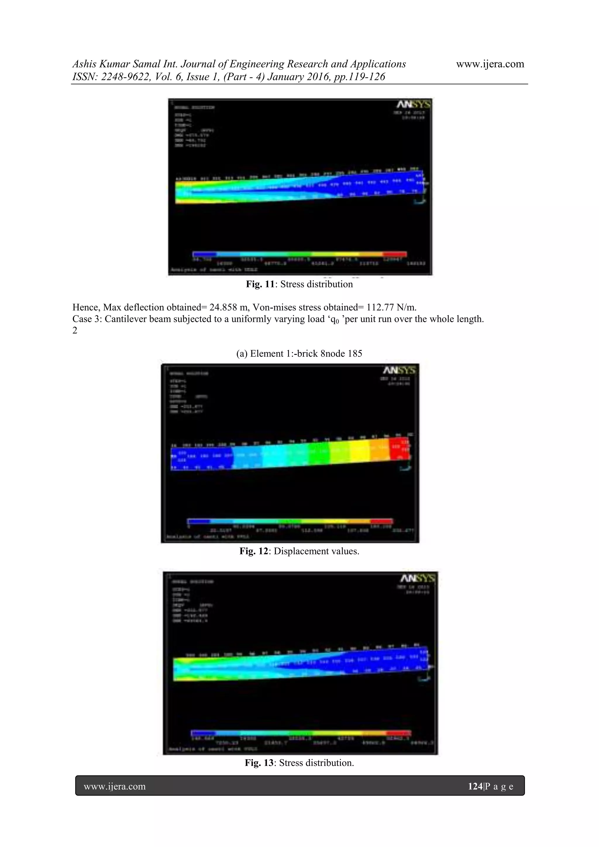
load applied at the free end, uniformly distributed load and uniformly varying load which runs over the whole
span. The weight of the beam is assumed to be negligible. It is also assumed that the beam is inextensible and so
the strains are also negligible. Considering this assumptions at first using the Bernoulli-Euler’s bending-
moment curvature relationship, the approximate solutions of the cantilever beam was obtained from the general
set of equations. Then assuming a particular set of dimensions, the deflection and stress values of the beam are
calculated analytically. Finite element analysis of the beam was done considering various types of elements
under different loading conditions in ANSYS 14.5. The various numerical results were generated at different
nodal points by taking the origin of the Cartesian coordinate system at the fixed end of the beam. The nodal
solutions were analyzed and compared. On comparing the computational and analytical solutions it was found
that for stresses the 8 node brick element gives the most consistent results and the variation with the analytical
results is minimum.
Keywords: Cantilever, loading, ANSYS, element, Cartesian Coordinate System.
I. Introduction
In this paper cantilever beam [1] has been analyzed.
All the following cases represents statically
determinate beam since the reactions at the support
can be determined from the equation of statics. The
measure to which a structural member gets deviated
from the initial position is called deflection. The
deflected distance of a member under a load is
directly related to the slope of the deflected shape of
the member under that load. While the beam gets
deflected under the loads, bending occurs in the same
plane due to which stresses are developed. Here the
deflection of the beam element is calculated by using
the Euler-Bernoulli’s beam equation [2] and the
bending stresses using the general standard bending
equation analytically. ANSYS [3] has been used to
do the computational analysis. It is general purpose
finite element analysis [4] software which enables the
product development process at less computational
and financial expenditure. Researchers [5-9] have
used Ansys for the calculation and validation of
experimental results.
II. Theoretical Calculations
First a uniform rectangular cross-sectional beam of
linear elastic isotropic homogeneous material has
been considered. The beam is taken mass less and
inextensible hence have developed no strains. It is
subjected to a vertical point load at the tip of its free
end and the differential equation is developed
mathematically. Similarly it is done with the same
value of uniformly distributed load and uniformly
varying load over the whole span. Using the
Bernoulli-Euler’s elastic curve equation [1] the
following relationship is obtained:
EI (d2
y/dx2) =M (1)
Where E is modulus of elasticity which is of constant
value.
I is moment of inertia=bh3
/12, b=width of beam,
h=height of beam.
M=moment developed.
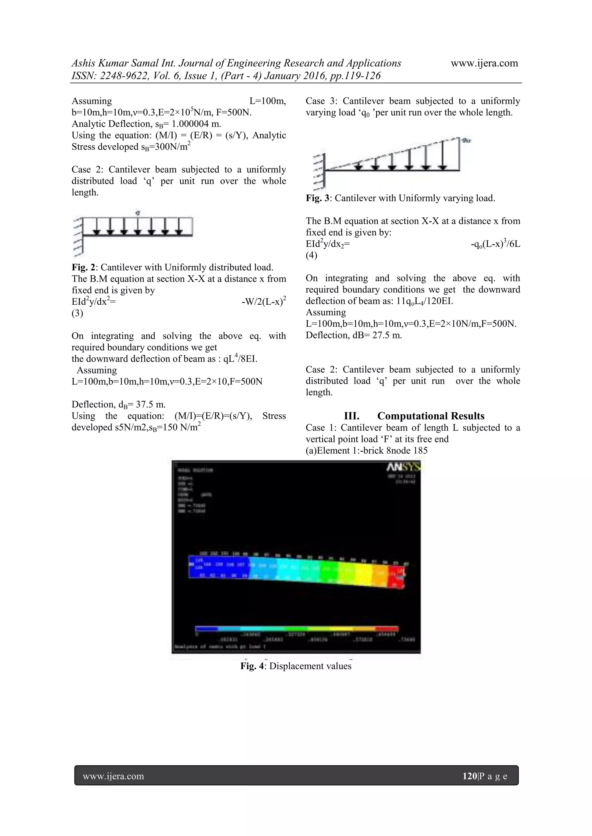
Case 1: Cantilever beam of length L subjected to a
vertical point load ‘F’ at its free end .
Fig. 1: Cantilever with vertical load at free end
The B.M equation at section X-X at a distance x from
fixed end is given by:
Eid2
y/dx2= -F(L-x) (2)
On integrating and solving the above eq. with
required boundary conditions we get the downward
deflection of beam as: FL3
/3 EI .
RESEARCH ARTICLE OPEN ACCESS](https://image.slidesharecdn.com/q6104119126-160727053429/75/Analysis-of-Stress-and-Deflection-of-Cantilever-Beam-and-its-Validation-Using-ANSYS-1-2048.jpg)
![Ashis Kumar Samal Int. Journal of Engineering Research and Applications www.ijera.com
ISSN: 2248-9622, Vol. 6, Issue 1, (Part - 4) January 2016, pp.119-126
www.ijera.com 126|P a g e
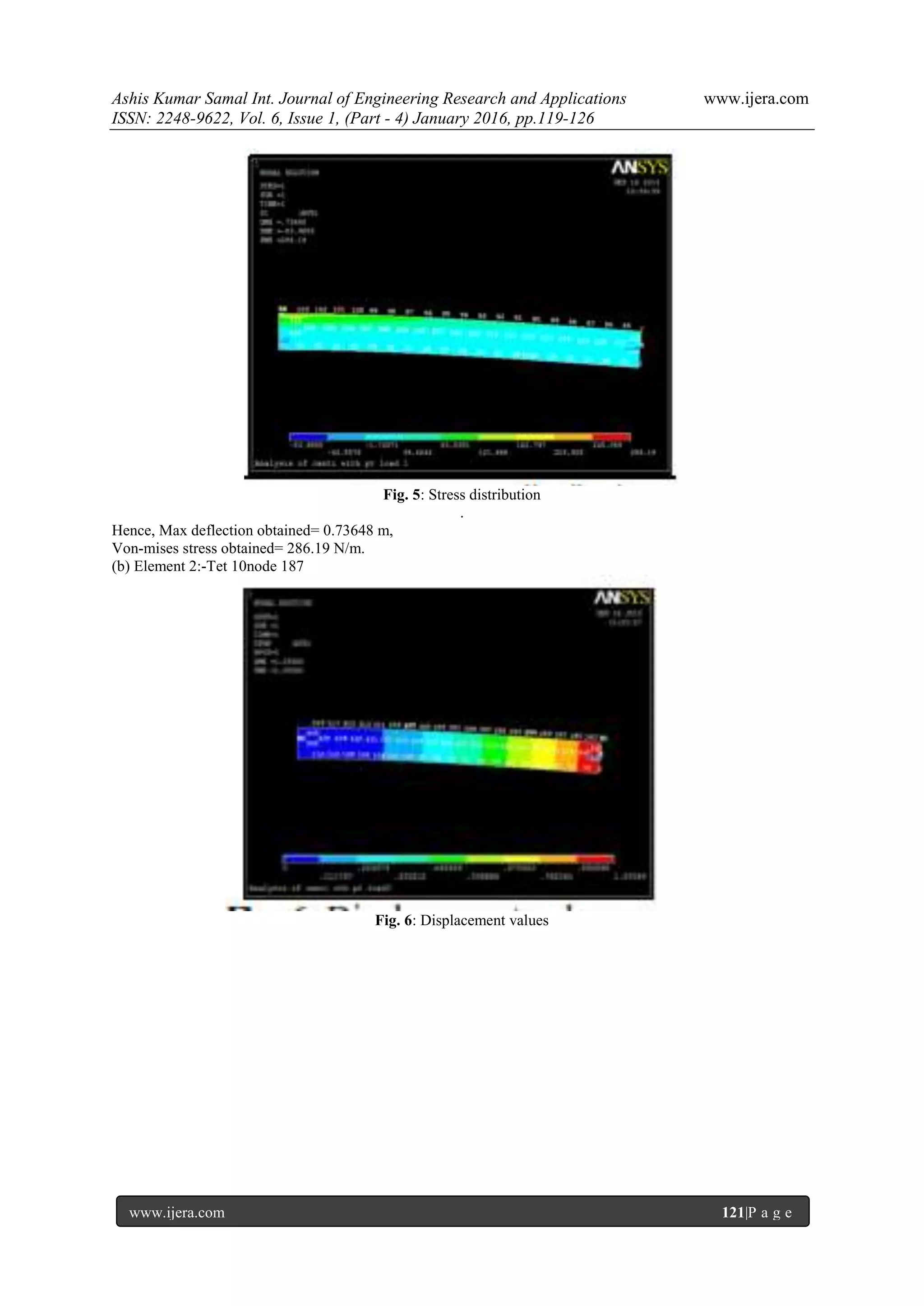
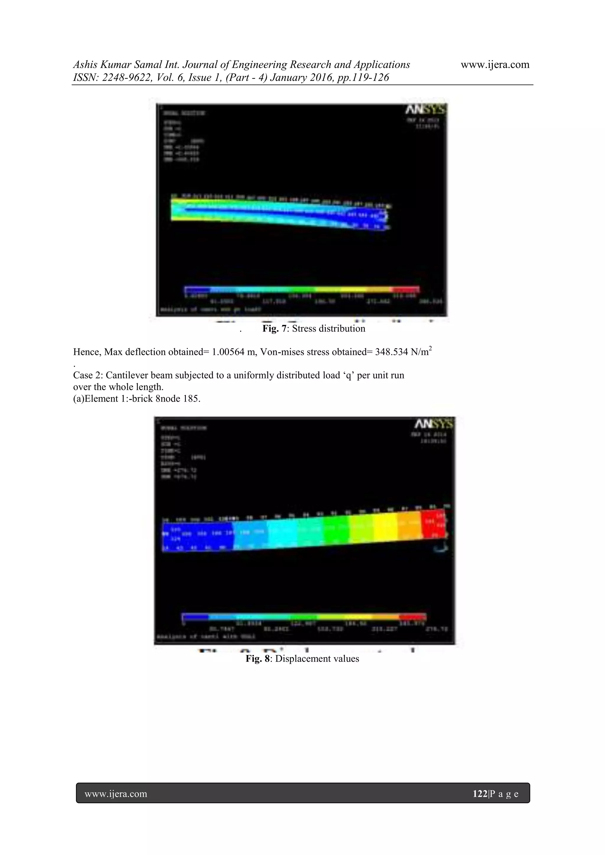
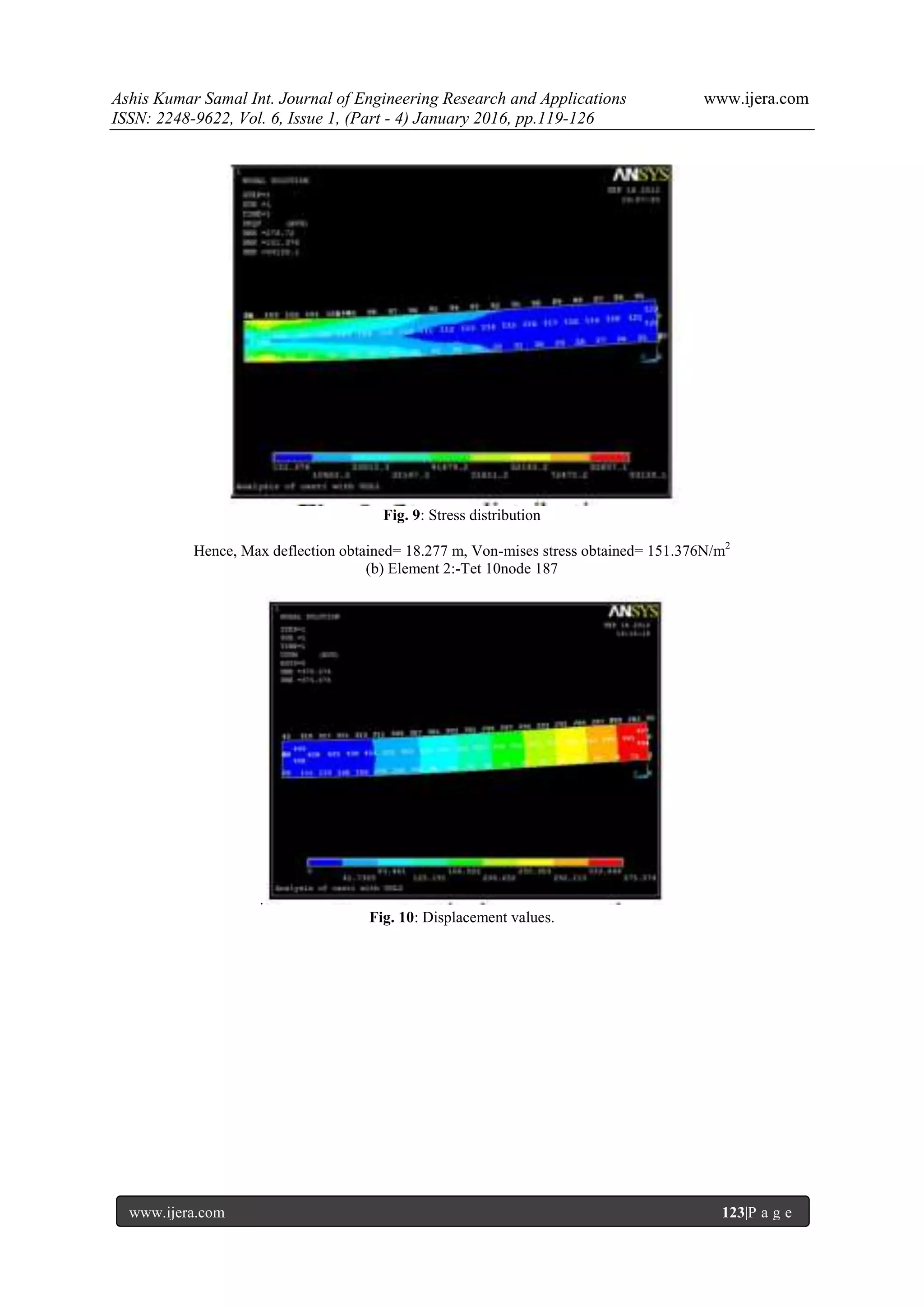
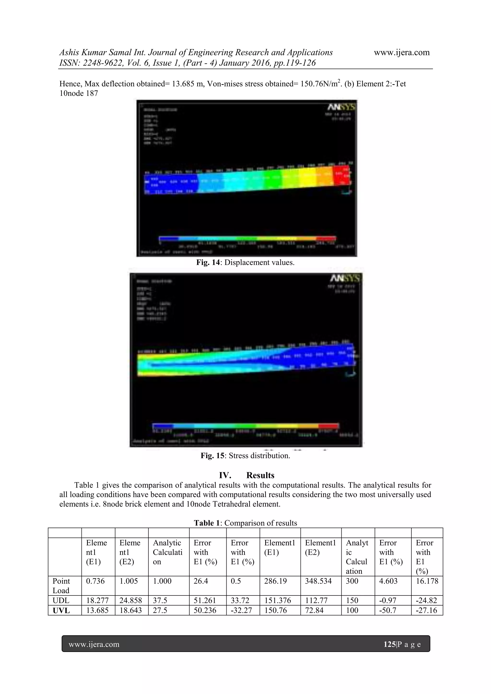
V. Conclusions:
From the above table it can be concluded that
using Ansys the deflection is more accurate when
element 2 i.e. 10node Tetrahedral element is used but
for stresses 8node brick element gives a better results.
Hence for determination of deflection 10node
Tetrahedral element should be used whereas for
stresses 8node brick element is more appropriate.
References:
[1] Hool, George A.; Johnson, Nathan Clarke
(1920). "Elements of Structural Theory -
Definitions". Handbook of Building
Construction (Google Books).vol. 1 (1st
ed.).New York McGraw-Hill. p. 2.
Retrieved 2008-10-01. "A cantilever beam is
a beam having one end rigidly fixed and the
other end free."
[2] Timoshenko, S., (1953), History of strength
of materials, McGraw-Hill New York.
[3] ANSYS.11.0 documentation.
[4] Strang, Gilbert; Fix, George (1973). An
Analysis of The Finite Element Method.
Prentice Hall. ISBN 0-13-032946-0.
[5] Timoshenko, S.P. and D.H. Young.
Elements of Strength of Materials, 5th
edition. (MKS System).
[6 ] Babuška, Ivo; Banerjee, Uday; Osborn,
John E. (June 2004). "Generalized Finite
Element Methods: Main Ideas, Results, and
Perspective".International Journal of
Computational Methods 1 (1): 67–103.
doi:10.1142/S0219876204000083].
[7] E.A. Witmer (1991-1992). "Elementary
Bernoulli-Euler Beam Theory". MIT
Unified Engineering Course Notes.
[8] Ballarini, Roberto (April 18, 2003). "The Da
Vinci-Euler-Bernoulli Beam Theory?".
Mechanical Engineering Magazine Online.
Retrieved 2006-07-22.
[9] Truesdell, C., (1960), The rational
mechanics of flexible or elastic bodies 1638-
1788, Venditioni Exponunt Orell Fussli
Turici.](https://image.slidesharecdn.com/q6104119126-160727053429/75/Analysis-of-Stress-and-Deflection-of-Cantilever-Beam-and-its-Validation-Using-ANSYS-8-2048.jpg)

This document analyzes the stress and deflection of a cantilever beam under different loading conditions using analytical calculations and finite element analysis in ANSYS. Analytical calculations are performed for three cases: a point load at the free end, uniform distributed load, and uniform varying load. Computational analysis using 8-node brick and 10-node tetrahedral elements in ANSYS is conducted for the same cases. Results show that the 10-node tetrahedral element more accurately calculates deflection while the 8-node brick element better calculates stresses when compared to analytical solutions.