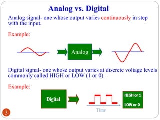
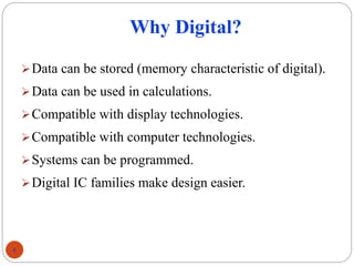
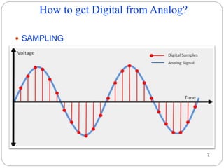
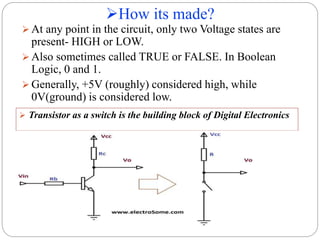
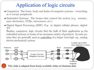
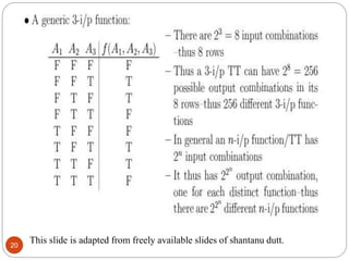
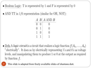
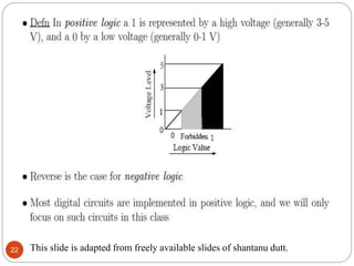
1. Digital Electronics
Presentation on
Lecture1 : Introduction to Digital
Electronics
Presented By :
Parag Parandkar
1
Presentation on
Lecture1 : Introduction to
Digital Electronics
Presented By :
Parag Parandkar
2. Contents
Analog vs. Digital
Why Digital or Analog?
Advantages of digital over analog
How to get digital from analog
How its made
Where are they used
How do they look
What’s inside
Levels of integration
Digital design as Logic Circuits and its applications
Number System and Interconversions
2
3. Analog vs. Digital
Analog signal- one whose output varies continuously in step
with the input.
Example:
Analog
Analog
Digital signal- one whose output varies at discrete voltage levels
commonly called HIGH or LOW (1 or 0).
Example:
3
4. Why Digital?
Data can be stored (memory characteristic of digital).
Data can be used in calculations.
Compatible with display technologies.
Compatible with computer technologies.
Systems can be programmed.
Digital IC families make design easier.
4
5. Why Analog?
Most “real-world” events are analog in
nature.
Analog processing is usually simpler.
Analog processing is usually faster.
Traditional electronic systems were
mostly analog in nature.
5
6. Benefits of Digital over Analog
Reproducibility
Not effected by noise means quality
Ease of design
Data protection
Programmable
Speed
Economy
6
8. How its made?
8
At any point in the circuit, only two Voltage states are
present- HIGH or LOW.
Also sometimes called TRUE or FALSE. In Boolean
Logic, 0 and 1.
Generally, +5V (roughly) considered high, while
0V(ground) is considered low.
Transistor as a switch is the building block of Digital Electronics
9. Where are they used?
9
Think of any Real Life Application of Logic Gates!
• What are the
inputs?
• What’s the
output?
• Which logic gate
should be used?
12. Complexity in a digital design
Complexity can, and generally does,
surpass human capability.
– 10-100 million transistors/cm2 now.
– 100-1000 million transistors/cm2 in 10
years.
Provides motivation for computer-based
design techniques.
Most engineering work is done with CAD
packages.
12
13. Levels of Integration
Integration levels
SSI (small scale integration)
Introduced in late 1960s
1-10 gates (previous examples)
MSI (medium scale integration)
Introduced in late 1960s
10-100 gates
LSI (large scale integration)
Introduced in early 1970s
100-10,000 gates
VLSI (very large scale integration)
Introduced in late 1970s
More than 10,000 gates
13
14. Digital Circuits
A digital circuit is often constructed from small electronic
circuits called logic gates that can be used to create
combinational logic. Each logic gate represents a function of
boolean logic.
A logic gate is an arrangement of electrically controlled
switches, better known as transistors.
The output of a logic gate is an electrical flow or voltage, that
can, in turn, control more logic gates.
Integrated circuits are the least expensive way to make logic
gates in large volumes.
Another form of digital circuit is constructed from PLD for
small volume.
When the volumes are medium to large, microcontroller is
programmed to make an embedded system. These are usually
programmed by software engineers.
14
15. Application of logic circuits
This slide is adapted from freely available slides of shantanu dutt.
15
16. This slide is adapted from freely available slides of shantanu dutt.
16
17. The role of logic
This slide is adapted from freely available slides of shantanu dutt.
17
18. This slide is adapted from freely available slides of shantanu dutt.
18
19. This slide is adapted from freely available slides of shantanu dutt.
19
20. This slide is adapted from freely available slides of shantanu dutt.
20
21. This slide is adapted from freely available slides of shantanu dutt.
21
22. This slide is adapted from freely available slides of shantanu dutt.
22