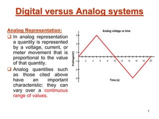
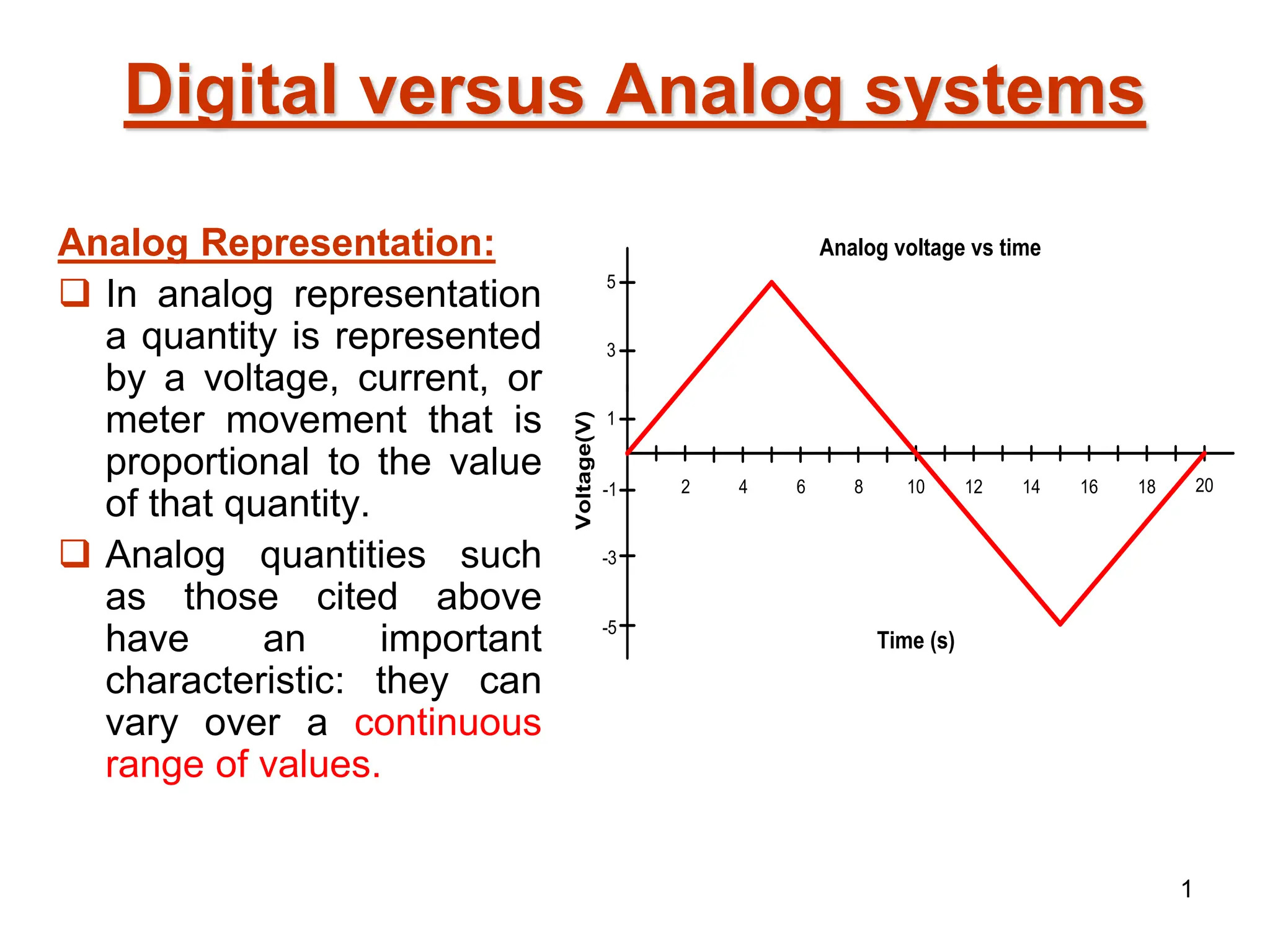
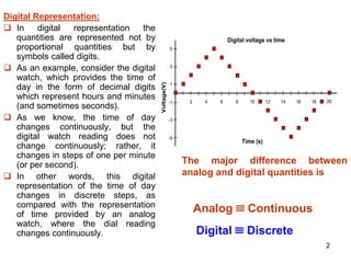
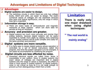
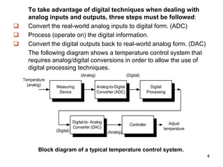
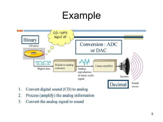
The document describes the syllabus for the Logic Design course 10CS33. It covers 8 units: 1) Digital Principles and Logic, 2) Combinational Logic Circuits, 3) Data Processing Circuits, 4) Clocks and Flip-Flops, 5) Registers, 6) Counters, 7) Design of Sequential Circuits, and 8) D/A and A/D Conversion. Each unit covers basic concepts in digital logic and their implementation in hardware description language. The document also lists reference books for the course.
This document provides an introduction to digital logic design concepts. It defines analog and digital quantities, explaining that digital systems represent information using discrete binary values of 1s and 0s. The advantages of digital systems are ease of design, accuracy, programmability and reliability. Common digital components like logic gates, flip-flops, and integrated circuits are described. Fundamental logic functions such as arithmetic, comparison, encoding/decoding are also introduced.
1. The document discusses digital circuits and introduces the key differences between analog and digital signals. Analog signals are continuous in time and value, while digital signals are discrete in time and value, taking only binary values of 1 and 0.
2. It then covers digital systems, explaining they use a building block approach with logic gates. Digital signals only have two values, 1 and 0, representing the presence or absence of a condition.
3. The document compares analog and digital systems, noting digital systems are easier to design, more flexible, efficient at information storage, and less affected by noise than analog systems. Digital systems also have lower costs and greater accuracy.
Logic Gates
This information sheet purposes to explain details on logic gates. The emphasis is on the operation, application and troubleshooting of logic gates. The relationship of input and output waveforms of a gate using timing diagram and truth table are thoroughly covered.
Introduction to Analog and Digital Systems - Basic definition, Representation, Examples and applications of Analog and Digital Systems - Advantages of Digital system over Analog system - Process of conversion from Analog to Digital and Digital to Analog signal - Digitization Examples - Signal representation of voltage and current in terms of Binary values - Representations of Binary quantities using different terminologies - IC Complexity classification - IC Layout - Development of ICs in terms of size
The hybrid energy storage system is the technological development to enhance the life of the primary energy storage device. Secondary storage system need to be identified based on the power or energy density to support accordingly to meet the power balance is a challenging task, The increasing demand for achieving high voltage from low voltage levels has become a challenging task. Low voltage DC supply could be easily extracted using Solar PV (Photo Voltaic) System. High power applications demand is moving towards HVDC, drive train, DC microgrid, Electric Vehicle (4 wheeler, 3wheeler, and 2wheeler), Elevators, and robotic applications. The extraction of power from a low voltage DC source to meet the higher power application requires high efficient, high step-up with high gain DC-DC Converters. Therefore, to boost the voltage from solar PV to a high level a high step-up and efficient DC-DC converter need to be designed and developed which paves way for research problem identification in the converter topology. Even using a multi-level inverter for high-power electric vehicle application is also another research area in electric vehicle technology for improved power output.
This document provides an introduction to digital logic. It begins with an overview of analog versus digital signals, noting that digital signals can only take discrete values while analog signals are continuous. It then defines digital systems as those that process digital signals using components like logic gates and flip-flops. Some disadvantages of digital systems are that they use more energy and can be fragile if data is lost. The document also discusses how information is represented using binary values and physical signal examples over time. It concludes with some applications of logic circuits in computers, embedded systems, and digital signal processing.
This document discusses units, standards, and definitions used in instrumentation. It covers the International System of Units (SI) which defines seven base units and two supplementary units. It also discusses analog and digital representations of data, common units like current and pressure used to transmit analog signals, conversions between analog and digital formats, and different types of control systems from simple on/off control to networked digital control and programmable logic controllers. Finally, it examines sensor time response and how the output of a sensor may lag behind rapid changes in its input due to its finite response time.
This chapter discusses digital control systems, including their components and operation. Digital control systems consist of a digital controller, analog to digital converter (ADC), and digital to analog converter (DAC). The ADC converts analog signals from sensors into digital signals for the controller. The controller processes the digital signals and outputs digital signals to the DAC. The DAC then converts the digital outputs back into analog signals to act on the physical system. Key aspects covered include comparing analog and digital control loops, describing the operation of ADCs and DACs, and selecting appropriate sampling frequencies to avoid signal distortion.
The document provides an introduction to analog and digital electronics. It discusses:
1) The prerequisites for the course including basic electrical engineering, C programming, and basic electronics.
2) The differences between analog and digital representations, with analog being continuous and digital being discrete.
3) Some key aspects of digital electronics including binary numbers, parallel vs serial transmission, memory, and the major parts of a digital computer like input, output, memory, arithmetic/logic, and control units.
4) An overview of semiconductor devices like photodiodes, light emitting diodes (LEDs), and photocouplers along with their basic construction, working principles, and applications.
5) Different biasing
This document discusses the design of an embedded system for electronic voting with voter tracking. It begins with an introduction to embedded systems, their characteristics, and applications. It then discusses the components of embedded systems, including microcontrollers, power supplies, LCD displays, and GSM modules. It covers the hardware and software components, and describes future enhancements and conclusions. The overall purpose is to present the design of a GSM-based electronic voting machine that sends polling results to a base station via the mobile network while also tracking voters using infrared sensors.
This document provides information on transducers and sensors. It begins with an introduction to basic principles and classifications of instruments such as moving coil, moving iron, digital multimeter, and digital storage oscilloscope. It then discusses transducer classification including capacitive, inductive, linear variable differential transformer (LVDT), thermistors, thermocouples, piezoelectric, photoelectric, Hall effect, and introduction to optoelectronics devices. Specific sensors like light dependent resistor, photodiodes, phototransistors, photovoltaic cells, optocouplers, liquid crystal display, proximity, IR, pressure, and biosensors are also introduced. Workings of digital multimeters and digital
The document provides an overview of digital number systems and codes. It discusses binary, octal, hexadecimal, signed magnitude, one's complement, two's complement and excess representations. Binary is the base system for digital circuits due to its two voltage levels. Negative numbers can be represented using the sign bit in signed magnitude or by taking the complement. Two's complement is commonly used as it allows addition/subtraction of positive and negative numbers without checking signs.
1) The document discusses analog and digital representation of physical quantities. It explains that analog representation uses proportional quantities that vary continuously, while digital representation uses discrete symbols or digits.
2) It then describes different types of data acquisition systems - analog systems that use continuously varying representations and digital systems that use discrete representations.
3) The key techniques of analog to digital conversion (ADC) and digital to analog conversion (DAC) are explained. ADC converts a continuous analog signal to a discrete digital signal, while DAC performs the reverse conversion.
Digital electronics handles discrete digital signals rather than continuous analog signals. The document discusses the history of digital electronics from vacuum tubes to transistors to integrated circuits. It describes logic gates as basic building blocks and CMOS as the basic building block of today's ICs. Applications of digital electronics include secure data transmission and encryption. The future of digital electronics is promising due to advantages like smaller size, lower power consumption, and ability to add new functions through software.
Is an introduction for digital design crash course using Verilog,
Those slides are just quick refreshment for most important parts in logic circuits, Brief history about the field and steps we follow to get a chip.
Telemetry and data acquisition systems allow measurement data to be transmitted over long distances. There are two main types - analog and digital systems. Analog systems transmit continuous signals, while digital systems convert signals to discrete numeric values. Key components include sensors, signal conditioners, multiplexers, analog-to-digital converters, and recorders. Telemetry is used in applications like environmental monitoring, spacecraft, and medical devices to transmit sensor measurements from remote locations.
This document provides information about a digital electronics course syllabus, including:
1. The course is titled EC8392 Digital Electronics and covers topics such as digital fundamentals, combinational and sequential circuit design, memory devices, and digital integrated circuits.
2. The syllabus is divided into 5 units that cover these topics in more detail over 45 class periods.
3. The objectives of the course are to present digital fundamentals, design digital circuits, explain sequential circuits and memory technology, and introduce electronic circuit implementation.
This document discusses numerical data representation and digital and analog systems. It notes that there are two types of numerical representation: analog and digital. It also describes two types of systems: analog systems, which use analog representations, and digital systems, which use digital representations. The document outlines several advantages of digital systems, such as being easier to design, having greater accuracy and precision, and being less affected by noise. It also notes a limitation of digital systems is that the real world is analog. To take advantage of digital techniques, analog inputs must be converted to digital forms, operations performed digitally, and digital outputs converted back to analog forms.
temperature dependent dc fan speed controller withou using micrcontrollerDeepak Yadav
This document describes the development of an automatic fan system that controls fan speed based on room temperature. It uses a LM35 temperature sensor to detect temperature changes and an LM3914 integrated circuit to automatically adjust the fan speed through relays. The system aims to enable automatic fan speed control, develop an automatic fan system that changes speed according to temperature, and allow users to view the temperature and speed status on an LCD display. It works by sensing temperature with the LM35 sensor and sending the output to the LM3914 IC, which activates relays to change the fan speed as the temperature rises or falls.
1) Today's fast growing technology needs the evolution of digital electronics as speed, space, and accuracy are key parameters of digital systems.
2) While every signal is analog by nature, conversions are made for signals to work in digital systems. Conversion from analog to digital and back occurs, though information is lost.
3) Digital electronics have infinite applications seen everywhere from computing to communication. Their applications explain the need for digital electronics.
unit 4 smartsensors and application.pptxAanshuSingh3
This document discusses smart sensors and their applications. It defines smart sensors as sensors that can perform ranging, calibration, and decision making for communication when combined with interface electronics. It describes the key components of smart sensors including primary sensors, excitation, amplification, filters, converters, compensation, information coding/processing, and data communication. It also discusses standards for smart sensor interfaces and gives examples of sensor applications in automobiles, homes, aerospace, manufacturing, and environmental monitoring.
This document provides information about digital electronics and different number systems used in digital systems. It begins with an overview of digital electronics and its applications beyond just computers. It then discusses analog vs digital quantities and representations. The main number systems covered are decimal, binary, octal, and hexadecimal. The document explains that computers use binary numbers internally and discusses why binary is used over decimal. It provides details on the characteristics and bases of each number system.
In digital logic and computing, a counter is a device which stores the number of times a particular event or process has occurred, often in relationship to a clock signal. CMOS devices are designed for high noise immunity and low static power consumption. CMOS accomplishes current reduction by complementing every nMOSFET with a pMOSFET and connecting both gates and both drains together. A high voltage on the gates will cause the nMOSFET to conduct and the pMOSFET to not conduct, while a low voltage on the gate causes the reverse. This arrangement greatly reduces power consumption and heat generation .Finally we proposed counter using SRAM model, provides the best resolution, high output current and good output-input current linearity.
Use PyCharm for remote debugging of WSL on a Windo cf5c162d672e4e58b4dde5d797...shadow0702a
This document serves as a comprehensive step-by-step guide on how to effectively use PyCharm for remote debugging of the Windows Subsystem for Linux (WSL) on a local Windows machine. It meticulously outlines several critical steps in the process, starting with the crucial task of enabling permissions, followed by the installation and configuration of WSL.
The guide then proceeds to explain how to set up the SSH service within the WSL environment, an integral part of the process. Alongside this, it also provides detailed instructions on how to modify the inbound rules of the Windows firewall to facilitate the process, ensuring that there are no connectivity issues that could potentially hinder the debugging process.
The document further emphasizes on the importance of checking the connection between the Windows and WSL environments, providing instructions on how to ensure that the connection is optimal and ready for remote debugging.
It also offers an in-depth guide on how to configure the WSL interpreter and files within the PyCharm environment. This is essential for ensuring that the debugging process is set up correctly and that the program can be run effectively within the WSL terminal.
Additionally, the document provides guidance on how to set up breakpoints for debugging, a fundamental aspect of the debugging process which allows the developer to stop the execution of their code at certain points and inspect their program at those stages.
Finally, the document concludes by providing a link to a reference blog. This blog offers additional information and guidance on configuring the remote Python interpreter in PyCharm, providing the reader with a well-rounded understanding of the process.
More Related Content
Similar to chapter1.pptx digital logic design for electrical engineering
This document discusses units, standards, and definitions used in instrumentation. It covers the International System of Units (SI) which defines seven base units and two supplementary units. It also discusses analog and digital representations of data, common units like current and pressure used to transmit analog signals, conversions between analog and digital formats, and different types of control systems from simple on/off control to networked digital control and programmable logic controllers. Finally, it examines sensor time response and how the output of a sensor may lag behind rapid changes in its input due to its finite response time.
This chapter discusses digital control systems, including their components and operation. Digital control systems consist of a digital controller, analog to digital converter (ADC), and digital to analog converter (DAC). The ADC converts analog signals from sensors into digital signals for the controller. The controller processes the digital signals and outputs digital signals to the DAC. The DAC then converts the digital outputs back into analog signals to act on the physical system. Key aspects covered include comparing analog and digital control loops, describing the operation of ADCs and DACs, and selecting appropriate sampling frequencies to avoid signal distortion.
The document provides an introduction to analog and digital electronics. It discusses:
1) The prerequisites for the course including basic electrical engineering, C programming, and basic electronics.
2) The differences between analog and digital representations, with analog being continuous and digital being discrete.
3) Some key aspects of digital electronics including binary numbers, parallel vs serial transmission, memory, and the major parts of a digital computer like input, output, memory, arithmetic/logic, and control units.
4) An overview of semiconductor devices like photodiodes, light emitting diodes (LEDs), and photocouplers along with their basic construction, working principles, and applications.
5) Different biasing
This document discusses the design of an embedded system for electronic voting with voter tracking. It begins with an introduction to embedded systems, their characteristics, and applications. It then discusses the components of embedded systems, including microcontrollers, power supplies, LCD displays, and GSM modules. It covers the hardware and software components, and describes future enhancements and conclusions. The overall purpose is to present the design of a GSM-based electronic voting machine that sends polling results to a base station via the mobile network while also tracking voters using infrared sensors.
This document provides information on transducers and sensors. It begins with an introduction to basic principles and classifications of instruments such as moving coil, moving iron, digital multimeter, and digital storage oscilloscope. It then discusses transducer classification including capacitive, inductive, linear variable differential transformer (LVDT), thermistors, thermocouples, piezoelectric, photoelectric, Hall effect, and introduction to optoelectronics devices. Specific sensors like light dependent resistor, photodiodes, phototransistors, photovoltaic cells, optocouplers, liquid crystal display, proximity, IR, pressure, and biosensors are also introduced. Workings of digital multimeters and digital
The document provides an overview of digital number systems and codes. It discusses binary, octal, hexadecimal, signed magnitude, one's complement, two's complement and excess representations. Binary is the base system for digital circuits due to its two voltage levels. Negative numbers can be represented using the sign bit in signed magnitude or by taking the complement. Two's complement is commonly used as it allows addition/subtraction of positive and negative numbers without checking signs.
1) The document discusses analog and digital representation of physical quantities. It explains that analog representation uses proportional quantities that vary continuously, while digital representation uses discrete symbols or digits.
2) It then describes different types of data acquisition systems - analog systems that use continuously varying representations and digital systems that use discrete representations.
3) The key techniques of analog to digital conversion (ADC) and digital to analog conversion (DAC) are explained. ADC converts a continuous analog signal to a discrete digital signal, while DAC performs the reverse conversion.
Digital electronics handles discrete digital signals rather than continuous analog signals. The document discusses the history of digital electronics from vacuum tubes to transistors to integrated circuits. It describes logic gates as basic building blocks and CMOS as the basic building block of today's ICs. Applications of digital electronics include secure data transmission and encryption. The future of digital electronics is promising due to advantages like smaller size, lower power consumption, and ability to add new functions through software.
Is an introduction for digital design crash course using Verilog,
Those slides are just quick refreshment for most important parts in logic circuits, Brief history about the field and steps we follow to get a chip.
Telemetry and data acquisition systems allow measurement data to be transmitted over long distances. There are two main types - analog and digital systems. Analog systems transmit continuous signals, while digital systems convert signals to discrete numeric values. Key components include sensors, signal conditioners, multiplexers, analog-to-digital converters, and recorders. Telemetry is used in applications like environmental monitoring, spacecraft, and medical devices to transmit sensor measurements from remote locations.
This document provides information about a digital electronics course syllabus, including:
1. The course is titled EC8392 Digital Electronics and covers topics such as digital fundamentals, combinational and sequential circuit design, memory devices, and digital integrated circuits.
2. The syllabus is divided into 5 units that cover these topics in more detail over 45 class periods.
3. The objectives of the course are to present digital fundamentals, design digital circuits, explain sequential circuits and memory technology, and introduce electronic circuit implementation.
This document discusses numerical data representation and digital and analog systems. It notes that there are two types of numerical representation: analog and digital. It also describes two types of systems: analog systems, which use analog representations, and digital systems, which use digital representations. The document outlines several advantages of digital systems, such as being easier to design, having greater accuracy and precision, and being less affected by noise. It also notes a limitation of digital systems is that the real world is analog. To take advantage of digital techniques, analog inputs must be converted to digital forms, operations performed digitally, and digital outputs converted back to analog forms.
temperature dependent dc fan speed controller withou using micrcontrollerDeepak Yadav
This document describes the development of an automatic fan system that controls fan speed based on room temperature. It uses a LM35 temperature sensor to detect temperature changes and an LM3914 integrated circuit to automatically adjust the fan speed through relays. The system aims to enable automatic fan speed control, develop an automatic fan system that changes speed according to temperature, and allow users to view the temperature and speed status on an LCD display. It works by sensing temperature with the LM35 sensor and sending the output to the LM3914 IC, which activates relays to change the fan speed as the temperature rises or falls.
1) Today's fast growing technology needs the evolution of digital electronics as speed, space, and accuracy are key parameters of digital systems.
2) While every signal is analog by nature, conversions are made for signals to work in digital systems. Conversion from analog to digital and back occurs, though information is lost.
3) Digital electronics have infinite applications seen everywhere from computing to communication. Their applications explain the need for digital electronics.
unit 4 smartsensors and application.pptxAanshuSingh3
This document discusses smart sensors and their applications. It defines smart sensors as sensors that can perform ranging, calibration, and decision making for communication when combined with interface electronics. It describes the key components of smart sensors including primary sensors, excitation, amplification, filters, converters, compensation, information coding/processing, and data communication. It also discusses standards for smart sensor interfaces and gives examples of sensor applications in automobiles, homes, aerospace, manufacturing, and environmental monitoring.
This document provides information about digital electronics and different number systems used in digital systems. It begins with an overview of digital electronics and its applications beyond just computers. It then discusses analog vs digital quantities and representations. The main number systems covered are decimal, binary, octal, and hexadecimal. The document explains that computers use binary numbers internally and discusses why binary is used over decimal. It provides details on the characteristics and bases of each number system.
In digital logic and computing, a counter is a device which stores the number of times a particular event or process has occurred, often in relationship to a clock signal. CMOS devices are designed for high noise immunity and low static power consumption. CMOS accomplishes current reduction by complementing every nMOSFET with a pMOSFET and connecting both gates and both drains together. A high voltage on the gates will cause the nMOSFET to conduct and the pMOSFET to not conduct, while a low voltage on the gate causes the reverse. This arrangement greatly reduces power consumption and heat generation .Finally we proposed counter using SRAM model, provides the best resolution, high output current and good output-input current linearity.
Similar to chapter1.pptx digital logic design for electrical engineering (20)
Use PyCharm for remote debugging of WSL on a Windo cf5c162d672e4e58b4dde5d797...shadow0702a
This document serves as a comprehensive step-by-step guide on how to effectively use PyCharm for remote debugging of the Windows Subsystem for Linux (WSL) on a local Windows machine. It meticulously outlines several critical steps in the process, starting with the crucial task of enabling permissions, followed by the installation and configuration of WSL.
The guide then proceeds to explain how to set up the SSH service within the WSL environment, an integral part of the process. Alongside this, it also provides detailed instructions on how to modify the inbound rules of the Windows firewall to facilitate the process, ensuring that there are no connectivity issues that could potentially hinder the debugging process.
The document further emphasizes on the importance of checking the connection between the Windows and WSL environments, providing instructions on how to ensure that the connection is optimal and ready for remote debugging.
It also offers an in-depth guide on how to configure the WSL interpreter and files within the PyCharm environment. This is essential for ensuring that the debugging process is set up correctly and that the program can be run effectively within the WSL terminal.
Additionally, the document provides guidance on how to set up breakpoints for debugging, a fundamental aspect of the debugging process which allows the developer to stop the execution of their code at certain points and inspect their program at those stages.
Finally, the document concludes by providing a link to a reference blog. This blog offers additional information and guidance on configuring the remote Python interpreter in PyCharm, providing the reader with a well-rounded understanding of the process.
Design and optimization of ion propulsion dronebjmsejournal
Electric propulsion technology is widely used in many kinds of vehicles in recent years, and aircrafts are no exception. Technically, UAVs are electrically propelled but tend to produce a significant amount of noise and vibrations. Ion propulsion technology for drones is a potential solution to this problem. Ion propulsion technology is proven to be feasible in the earth’s atmosphere. The study presented in this article shows the design of EHD thrusters and power supply for ion propulsion drones along with performance optimization of high-voltage power supply for endurance in earth’s atmosphere.
Introduction- e - waste – definition - sources of e-waste– hazardous substances in e-waste - effects of e-waste on environment and human health- need for e-waste management– e-waste handling rules - waste minimization techniques for managing e-waste – recycling of e-waste - disposal treatment methods of e- waste – mechanism of extraction of precious metal from leaching solution-global Scenario of E-waste – E-waste in India- case studies.
Electric vehicle and photovoltaic advanced roles in enhancing the financial p...IJECEIAES
Climate change's impact on the planet forced the United Nations and governments to promote green energies and electric transportation. The deployments of photovoltaic (PV) and electric vehicle (EV) systems gained stronger momentum due to their numerous advantages over fossil fuel types. The advantages go beyond sustainability to reach financial support and stability. The work in this paper introduces the hybrid system between PV and EV to support industrial and commercial plants. This paper covers the theoretical framework of the proposed hybrid system including the required equation to complete the cost analysis when PV and EV are present. In addition, the proposed design diagram which sets the priorities and requirements of the system is presented. The proposed approach allows setup to advance their power stability, especially during power outages. The presented information supports researchers and plant owners to complete the necessary analysis while promoting the deployment of clean energy. The result of a case study that represents a dairy milk farmer supports the theoretical works and highlights its advanced benefits to existing plants. The short return on investment of the proposed approach supports the paper's novelty approach for the sustainable electrical system. In addition, the proposed system allows for an isolated power setup without the need for a transmission line which enhances the safety of the electrical network
Rainfall intensity duration frequency curve statistical analysis and modeling...bijceesjournal
Using data from 41 years in Patna’ India’ the study’s goal is to analyze the trends of how often it rains on a weekly, seasonal, and annual basis (1981−2020). First, utilizing the intensity-duration-frequency (IDF) curve and the relationship by statistically analyzing rainfall’ the historical rainfall data set for Patna’ India’ during a 41 year period (1981−2020), was evaluated for its quality. Changes in the hydrologic cycle as a result of increased greenhouse gas emissions are expected to induce variations in the intensity, length, and frequency of precipitation events. One strategy to lessen vulnerability is to quantify probable changes and adapt to them. Techniques such as log-normal, normal, and Gumbel are used (EV-I). Distributions were created with durations of 1, 2, 3, 6, and 24 h and return times of 2, 5, 10, 25, and 100 years. There were also mathematical correlations discovered between rainfall and recurrence interval.
Findings: Based on findings, the Gumbel approach produced the highest intensity values, whereas the other approaches produced values that were close to each other. The data indicates that 461.9 mm of rain fell during the monsoon season’s 301st week. However, it was found that the 29th week had the greatest average rainfall, 92.6 mm. With 952.6 mm on average, the monsoon season saw the highest rainfall. Calculations revealed that the yearly rainfall averaged 1171.1 mm. Using Weibull’s method, the study was subsequently expanded to examine rainfall distribution at different recurrence intervals of 2, 5, 10, and 25 years. Rainfall and recurrence interval mathematical correlations were also developed. Further regression analysis revealed that short wave irrigation, wind direction, wind speed, pressure, relative humidity, and temperature all had a substantial influence on rainfall.
Originality and value: The results of the rainfall IDF curves can provide useful information to policymakers in making appropriate decisions in managing and minimizing floods in the study area.
An improved modulation technique suitable for a three level flying capacitor ...IJECEIAES
This research paper introduces an innovative modulation technique for controlling a 3-level flying capacitor multilevel inverter (FCMLI), aiming to streamline the modulation process in contrast to conventional methods. The proposed
simplified modulation technique paves the way for more straightforward and
efficient control of multilevel inverters, enabling their widespread adoption and
integration into modern power electronic systems. Through the amalgamation of
sinusoidal pulse width modulation (SPWM) with a high-frequency square wave
pulse, this controlling technique attains energy equilibrium across the coupling
capacitor. The modulation scheme incorporates a simplified switching pattern
and a decreased count of voltage references, thereby simplifying the control
algorithm.
Batteries -Introduction – Types of Batteries – discharging and charging of battery - characteristics of battery –battery rating- various tests on battery- – Primary battery: silver button cell- Secondary battery :Ni-Cd battery-modern battery: lithium ion battery-maintenance of batteries-choices of batteries for electric vehicle applications.
Fuel Cells: Introduction- importance and classification of fuel cells - description, principle, components, applications of fuel cells: H2-O2 fuel cell, alkaline fuel cell, molten carbonate fuel cell and direct methanol fuel cells.
chapter1.pptx digital logic design for electrical engineering
1. Digital versus Analog systems
Analog Representation:
In analog representation
a quantity is represented
by a voltage, current, or
meter movement that is
proportional to the value
of that quantity.
Analog quantities such
as those cited above
have an important
characteristic: they can
vary over a continuous
range of values.
2 10
8
6
4 16
14
12 20
18
Analog voltage vs time
Voltage(V)
Time (s)
5
3
1
-5
-3
-1
1
2. Digital Representation:
In digital representation the
quantities are represented not by
proportional quantities but by
symbols called digits.
As an example, consider the digital
watch, which provides the time of
day in the form of decimal digits
which represent hours and minutes
(and sometimes seconds).
As we know, the time of day
changes continuously, but the
digital watch reading does not
change continuously; rather, it
changes in steps of one per minute
(or per second).
In other words, this digital
representation of the time of day
changes in discrete steps, as
compared with the representation
of time provided by an analog
watch, where the dial reading
changes continuously.
2 10
8
6
4 16
14
12 20
18
Digital voltage vs time
Voltage(V)
Time (s)
5
3
1
-5
-3
-1
The major difference between
analog and digital quantities is
Analog Continuous
Digital Discrete
2
3. Advantages
Digital systems are easier to design.
The switching circuits in which there are only two voltage
levels, HIGH and LOW, are easier to design. The exact
numerical values of voltages are not important because
they have only logical significance; only the range in which
they fall is important.
Information storage is easy.
There are many types of semiconductor and magnetic
memories of large capacity which can store data for
periods as long as necessary.
Accuracy and precision are greater.
Digital systems are much more accurate and precise than
analog systems, because digital systems can be easily
expanded to handle more digits by adding more switching
circuits. Analog systems will be quite complex and costly for
the same accuracy and precision.
Digital systems are more versatile.
It is fairly easy to design digital systems whose operation is
controlled by a set of stored instructions called the
program. Any time the system operation is to be changed, it
can easily be accomplished by modifying the program
Digital circuits are less affected by noise.
Unwanted electrical signals are called noise. Noise is
unavoidable in any system. Since in analog systems the
exact values of voltages are important and in digital
systems only the range of values is important, the effect of
noise is more severe in analog systems. In digital systems,
noise is not critical as long as it is not large enough to
prevent us from distinguishing a HIGH from a LOW.
Advantages and Limitations of Digital Techniques
Limitation
There is really only
one major drawback
when using digital
techniques:
“ The real world is
mainly analog”
3
4. To take advantage of digital techniques when dealing with
analog inputs and outputs, three steps must be followed:
Convert the real-world analog inputs to digital form. (ADC)
Process (operate on) the digital information.
Convert the digital outputs back to real-world analog form. (DAC)
The following diagram shows a temperature control system that
requires analog/digital conversions in order to allow the use of
digital processing techniques.
Measuring
Device
Analog-to-Digital
Converter (ADC)
Digital
Processing
Digital-to- Analog
Converter (DAC)
Controller
Temperature
(analog)
(Analog) (Digital)
(Digital) (Analog)
Adjust
temperature
Block diagram of a typical temperature control system.
4
6. The need for conversion between analog and digital forms of
information can be considered a drawback because of the
added complexity and expense.
Another factor that is often important is the extra time required
to perform these conversions.
In many applications, these factors are outweighed by the
numerous advantages of using digital techniques, and so the
conversion between analog and digital quantities has become
quite commonplace in the current technology.
There are situations, however, where using only analog
techniques is simpler and more economical.
For example, the process of signal amplification is most easily accomplished
using analog circuitry.
It is becoming more and more common to see both digital and
analog techniques employed within the same system in order
to profit from the advantages of each.
In these hybrid systems, one of the most important parts of the
design phase involves determining what parts of the system
are to be analog and what parts are to be digital.
6
7. Binary logic Gates
The general public as being magical sometimes looks upon
computers, calculators, and other digital devices.
Actually, digital electronic devices are extremely logical in
their operation.
The basic building block of any digital circuit is a logic gate.
The logic gates we will use operate with binary numbers,
hence the term binary logic gates.
Logic gates are the building blocks for even the most
complex computers.
Logic gates can be constructed by using simple switches,
relays, transistors and diodes, or lCs.
Because of their availability, wide use, and low cost, ICs will
be used to construct digital circuits.
A variety of logic gates are available in all logic families
including TTL and CMOS. 7
8. Logic families
• There are a variety of circuit configurations
or more appropriately various approaches
used to produce different types of digital
integrated circuit.
• Each such fundamental approach is called
a logic family
• The idea is that different logic functions,
when fabricated in the form of an IC with
the same approach,or in other words
belonging to the same logic family, will
have identical electrical characteristics.8
9. Logic Families
• A digital system in general comprises
digital ICs performing different logic
functions, and choosing these ICs from the
same logic family guarantees that different
ICs are compatible with respect to each
other and that the system as a whole
performs the intended logic function
9
10. Logic Families
• The entire range of digital ICs is fabricated
using either bipolar devices(BJT) or MOS
devices or a combination of the two
• Different logic families falling in the first
category are called bipolar families,and
these include:
– diode logic (DL),
– resistor transistor logic (RTL),
– diode transistor logic (DTL),
10
11. Logic Families
– transistor transistor logic (TTL),
– emitter coupled logic (ECL), also known as
current mode logic(CML), and
– integrated injection logic (I2L).
11
12. Logic families
• The logic families that use MOS devices
as their basis are known as MOS families,
and the prominent members belonging to
this category are:
– the PMOS family(using P-channel
MOSFETs),
– the NMOS family (using N-channel
MOSFETs) and
– the CMOS family(using both N- and P-
channel devices).
• The Bi-MOS logic family uses both bipolar
and MOS devices.
12
13. Logic families
• Logic families that are still in widespread
use include TTL, CMOS, ECL, NMOS and
Bi-CMOS.
• The PMOS and I2L logic families, which
were mainly intended for use in custom
large-scale integrated(LSI) circuit devices,
have also been rendered more or less
obsolete, with the NMOS logic family
replacing them for LSI and VLSI
applications.
13
14. Digital Signals
Digital systems use the binary number system.
Therefore, two-state devices are used to represent the two binary digits 1 and 0 by
two different voltage levels, called HIGH and LOW.
If the HIGH voltage level is used to represent 1 and the LOW voltage level to
represent 0, the system is called the positive logic system.
On the other hand, if the HIGH voltage level represents 0 and the LOW voltage level
represents 1, the system is called the negative logic system.
Normally, the binary 0 and 1 are represented by the logic voltage levels 0V and +5 V.
So, in positive logic system, 1 is represented by + 5 V (HIGH) and 0 is represented
by 0 V (LOW); and in a negative logic system, 0 is represented by + 5 V (HIGH) and l
is represented by 0 V ( LOW).
Both positive and negative logics are used in digital systems, but the positive logic
is more common.
HIGH
LOW
Leading
edge
Trailing
edge
a) Positive pulse
HIGH
LOW
Leading
edge
Trailing
edge
b) Negative pulse
14
15. In reality, because of circuit variations, the 0 and 1 would be
represented by voltage ranges instead of particular voltage
levels.
Example of Voltages Level in TTL family
0V
2.0 V
0.8V
5.0V HIGH
(Logic 1)
Indeterminate
range
LOW
(Logic 0)
15
16. Waveform Characteristics
Most waveforms encountered in digital
systems are composed of series of pulses,
sometimes called pulse trains, and can be
classified as either periodic or nonperiodic.
A periodic pulse waveform is one that repeats
itself at a fixed interval, called a period (T).
The frequency (f) is the rate at which it
repeats itself and is measured in hertz (Hz).
A nonperiodic pulse waveform, of course,
does not repeat itself at fixed intervals and
may be composed of pulses of randomly
differing pulse widths and/or randomly differing
time intervals between the pulses. An example
of each type is shown in Figure 1.5.
The frequency (f) of a pulse (digital) waveform
is the reciprocal of the period. The relationship
between frequency and period is expressed as
follows:
An important characteristic of a periodic digital
waveform is its duty cycle. The duty cycle is
the ratio of the pulse width (tW) to the period
(T) and can be expressed as a percentage.
T1 T2 T3
Period = T1 = T2 =T3 =…=Tn
Frequency=1/T
T
1
f
f
1
T
100%
T
t
cycle
Duty W
T
Tw
Duty cycle = 50%
Periodic pulse-train
Non-Periodic pulse-train
T
Tw
Duty cycle = 75%
16
17. Pulse width(tw)
• Pulse width (tW): A measure of the
duration of the pulse. Is often defined as
time interval between 50% points on the
rising and falling edges
17
18. Timing diagram
• Clock:in digital system, all waveforms are
synchronized with basic timing waveform
called clock. The clock is periodic
waveform in which each interval between
pulses(period) equals the time for one bit
18
19. Timing Diagram
• Is a graph of digital waveform showing the
actual time relationship of two or more
waveform and how each waveform
changes in relation to the others.
19
20. application
• Digital technology is widely used.
Examples:
– Computers
– Manufacturing systems
– Medical Science
– Transportation
– Entertainment
– Telecommunications
20