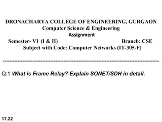
Here are the key points about Frame Relay and SONET/SDH:
Frame Relay:
- Frame relay is a standardized wide-area data networking technology that implements standards-based protocols.
- It is a packet switching protocol and operates at the physical and data link layer (layers 1 and 2) of the OSI model.
- Frame relay networks allow sharing of bandwidth and routes among multiple applications and users.
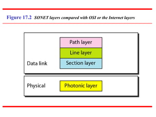
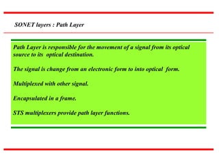
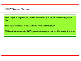
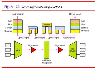
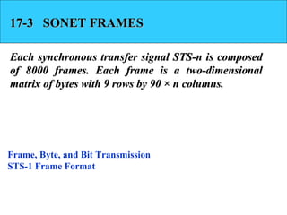
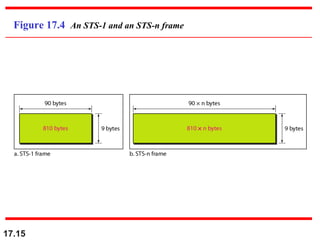
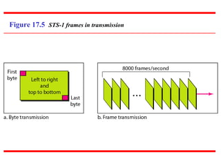
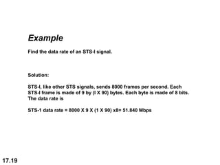
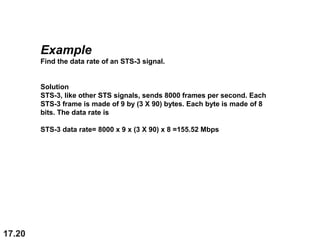
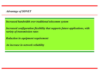
SONET/SDH:
- SONET is a telecommunications standard for synchronous data transmission on optical media. It was developed by ANSI.
- SDH is the international counterpart to SONET, developed by ITU-T. Though independent, they are fundamentally similar and