SlideShare a Scribd company logo
Lathe
2.1 Introduction
Lathe is the oldest machine tool invented, starting with the Egyptian tree lathes. In
the Egyptian tree lathe, one end of the rope wound round the work-piece is attached
to a flexible branch of a tree while the other end is pulled by the operator, thus
giving the rotary motion to the work-piece. This primitive device has evolved over
the last two centuries to be one of the most fundamental and versatile machine tools
with a large number of uses in all manufacturing shops.
2.2 Principle of Lathe
The principle form of surface produced in a lathe is the cylindrical surface. This is
achieved by rotating the work-piece while the single point cutting tool removes the
material by traversing in a direction parallel to the axis of rotation and termed as
turning as shown in Fig.2.1. The popularity of the lathe due to the fact that a large
variety of surfaces can be produced.
Fig.2.1. Cylindrical turning operation in a lathe
2.2
2.3 Classification of Lathe
Lathes of various designs and constructions have been developed to suit the various
conditions of metal machining. But all types of lathes work on the same principle of
operation and perform the same function.
The types generally used are:
i) Bench lathe
11J OUGGQ 13.1116
iii) Engine lathe
iv) Tool room lathe
v) Capstan and turret lathe
vi) Automatic lathe
vii) Special-purpose lathe.
2.3.1 Bench lathe
It is a very small lathe and is mounted on bench or cabinet. It is used for small and;
precision work since it is very accurate. It is usually provided with all the attachments
and is capable of performing all the operations.
2.3.2 Speed lathe
It is power driven simplest type of lathe mostly used for wood turning. Tools are
hand operated. Cone pulley is the only source provided for speed variation of the spindle.
2.3.3 Engine lathe or center lathe
It is a general-purpose lathe. It is normally used in all types of machine shops. It
carries a great historical significance that in the very early days of the development
of this machine it was driven by a steam engine. So it is called as engine lathe. The
stepped cone pulley arrangement is often used for varrying the speed of the lathe
spindle. The cutting tools are controlled either by hand or by power.
2.3.4 Tool room lathe
It is nothing but the same engine lathe but equipped with certain extra attachments
to make it suitable for relatively more accurate and precision type of work carried
out in a tool room.
2.3.5 Capstan and turret lathes
These are production lathes. Several tools are set on a revolving turret to facilitate in
doing large number of operations on a job with the minimum wastage of time.
2.3.6 Automatic lathes
These are high speed, heavy duty, mass production lathes with complete automatic
control. They are so designed that all the working and job handling movements of
Engine Lathe 2.3
the complete manufacturing process for a job are done automatically. After the job
is completed, the machine will continue to repeat the cycles producing identical
parts even with out the attention of an operator.
Another variety of this type of lathes includes the semi-automatic lathes in which
the mounting and removal of the work is done by the operator whereas all the
operations are performed by the machine automatically. Automatic lathes are available
having single or multi spindles.
2.3.7 Special-purpose lathes
As the name implies, they are used for special purposes and for jobs, which cannot
be accommodated for conveniently machined on a standard lathe. This category of
lathes include such machines as crank shaft turning lathes, wheel lathe, canOshaft
lathe, duplicating lathe, T-lathe and vertical lathe, Gap-bed lathe etc.
2.4 Constructional features of a engine lathe
A typical engine lathe is shown in Fig.2.2.
Fig.2.2. General view of a centre lathe showing various
mechanisms and features
2.4
The headstock is towards the left-most end on the bed and is fixed to it, which
houses the power source, the power transmission, gear box and the spindle. The
spindle is hollow and is sufficiently rigid to provide accurate rotary motion and
maintains perfect alignment with the lathe axis. A live centre fits into the Morse
taper is the spindle hole for the purpose of locating the work piece axis.
The main gear box provides the necessary spindle speeds considering the range
of materials to be turned in the lathe. The headstock also houses the feed gear box to
provide the various feed rates and thread cutting ranges.
The tailstock is towards the right most end on the bed, which provides a tailstock
spindle for the purpose of locating the long components by the use of centers. The
tailstock is movable on the inner guide ways provided on the bed to accommodate
the different lengths of work-pieces. It also serves the purpose of holding tools such
as center drill, twist drill, reamer, and etc. for making and finishing and finishing
holes in the components which are located in line with the axis of rotation.
The third major element in the lathe mechanism is the carriage, which provides
the necessary longitudinal motion to the cutting tool to generate the necessary surfaces.
This also houses the cross-slide for giving the motion (cross feed) to the cutting tool
in a direction perpendicular to the axis of rotation, the compound slide which provides
an auxiliary slide to get the necessary special motion for specific surface generations
and the tool post which allows for the mounting of the cutting tool.
The motion from the spindle motor is communicated to the carriage through a
lead screw. Engagement of the lead screw with the carriage is through the use of a
half nut. Though the lead screw could be used for feeding the cutting tool in a
direction parallel to the axis of rotating, many a time a separate feed rod is provided
for this function. The main reason is that the lead screw is more accurate and is used
only for thread cutting, such that it maintains its accuracy.
2.5 Description of various parts of lathe
2.5.1 BED
It is supported on broad box-section columns and is made of cast iron. Its upper
surface is either scraped or ground and the guiding and sliding surfaces are provided.
The bed consists of two heavy metal slides running lengthwise, with ways or V's
formed upon them. It is rigidly supported by cross girths. The outer guide ways
provide bearing and sliding surface for the carriage, and the inner ways for the
tailstock. Three major units mounted on bed are the headstock, the tailstock, and the
carriage. The scraped or ground guiding and sliding surfaces on the lathe bed ensure
the accuracy of alignment of these three units. The headstock is permanently fixed
to the bed; the tailstock is adjustable for position to accommodate work-pieces of
different lengths. The carriage can be traversed to and between the headstock and
the tailstock either manually or by power.
Lathe bed is made of high grade special cast iron having high vibration damping
qualities. Lathe bed is secured rigidly over cabinet leg and end leg and all other
parts are fitted on it (Refer Fig.2.3)
Engine Lathe 2.5
Top surface of bed is machined accurately.
The important considerations in design of lathe bed are its rigidity, alignment
and accuracy. In its use, every care should be taken to avoid formation of scratches;
nicks and dents by falling tools spanners and it should be lubricated regularly to
avoid rusting.
The lathe bed being the main guiding member for accurate machining work, it
should be sufficiently rigid to prevent deflection under cutting forces: should be
designed to resist the twisting stresses set up due to resultant of two forces: should
be seasoned naturally to relive the stresses set up during casting.
Fig.2.3
Fig.2.4 (a) shows a section through a typical lathe bed. It may be noted that while
top surfaces take the weight of the headstock, Carriage and tailstock, narrow surfaces
like 'G' act as guiding surfaces for movement of carriage and tailstock.
Fig.2.4 (b) shows some alternative arrangements of guides and supports. It is
important to note that guiding surfaces should not be too far apart to avoid cross-wind
or jamming effect.
Fig.2.4 (a) Section through lathe bed
Fig.2.4 (b) Alternative arrangements of guides on lathe bed
2.5.2 Headstock
It supports the main spindle in the bearings and aligns it properly. It also houses
necessary transmission mechanism with speed changing levers to obtain different
speeds cone pulley or gears or combination of both could be used to change speed
of spindle.
Accessories mounted on head stock spindle:
1) Three jaw chuck
2) Four jaw chuck
3) Lathe center and lathe dog
4) Collect chuck
5) Face plate
6) Magnetic chuck.
The complete head stock consists of the headstock casting which is located on the
ways of the bed at the lift side of the operator, the hollow spindle in which the live
center is rigidly held by a taper and the necessary gears and mechanisms for obtaining
the various spindly speeds. The centerline of the headstock is parallel to the guide
ways, in both horizontal and vertical planes. All the modern lathe employ all-geared
headstock. However, where greater simplicity and low cost are the criteria, cone-drive
headstock can be used. A geared headstock may be driven either direct from a line
shaft or from an independent motor, the drive being transmitted to the constant
speed main drive pulley. Headstock also incorporates the self-contained clutch and
brake mechanism by which the pulley may be coupled to the starting in the headstock
as required. Usually arrangements are provided so that when the pulley is running
free the spindle is braked automatically sliding gearing is generally employed for
obtaining the various speed changes, the gears being mounted on multi spindle
shafts and traversed axially thereon by external control levers through selector
mechanism.
2.6
Engine Lathe 2.7
A separate speed change gearbox is placed below headstock to reduce the speed
in order to have different feed rates for threading and automatic lateral movements
of carriage. The feed shaft is used for lost turning operations and lead screw is used
for cutting threads etc.
2.5.3 Main Spindle
It is a hollow cylindrical shaft and long slender jobs can pass through it. The spindle
end facing the fail stock is called the spindle nose. The spindle nose has a more
taper hole (Self-locking taper) and threads on outside. The morse taper is used to
accommodate lathe center or collet chuck and threaded portion for chuck or face
plate.
The design of the lathe spindle and its bearings forms important feature, as the
thrust of the cutting tool tends to deflect the spindle.
Fig.2.5. Main Spindle
Anti friction bearings are used in the headstock, and the spindle, which is made of
high-tensile steel suitably hardened and tempered, is supported in roller bearings.
The front spindle bearings take both the axial and radial loads on the spindle and
the rear bearing is so designed that the spindle may float axially from the front
bearings to allow the expansion and contraction. The front bearing is made adjustable
by a flanged plate and is preloaded in assembly to avoid any possibility of slackness
during the cut, with consequent vibration.
Fig.2.6. Schematic sketch of lathe
The spindle nose is designed for rapid mounting and removal of chucks and
fixtures on it, and also for positioning them accurately and securely. For this purpose,
2.8
screwed type spindle nose with two locating cylindrical surfaces in front and rear,
and threads in between is used. The overhang of the spindle nose is kept to minimum
to guard against bending. The spindle is made hollow to allow long bars to pass
through. On the front side, it has a taper socket to mount a live center, which rotates
with the spindle. The various face plates and chucks are secured to the flange of the
spindle nose by bolts or studs, and positioned by taper spigot.
2.5.4 Tailstock
It is movable casting located opposite to the headstock on the ways of the bed. It is
used for two purposes, (i) to support the other end of the work when being
machined, and (ii) to hold a tool for performing operations like drilling, reaming,
taping etc. it contains the dead centers the adjusting screw and the hand wheel. The
body of the tailstock is adjustable on the base which is mounted on the guide ways
of the bed and can be moved to and fro. The object of making the body adjustable on
the base is to provide means for lining up the center, carried in the moving spindle,
with the headstock center, or for offsetting this center to permit tapers to be turned.
Axial adjustment of the dead center in the movable spindle in the tailstock body is
provided for by means of a hand-wheel, which is attached to a screw engaging the
nuts in the rear of the movable spindle. It can be located by any position in the body
by means of a lever. The spindle is bored or ground to a taper gauge to take center
which may be of the fixed or revolving type.
Fig.2.7. Tailstock
Fig.2.7 shows sketch of tailstock. Tailstock spindle 4 is displayed in body 1 by
turning screw 5 with the hand wheel 7. Spindle is fixed in position by operating
lever 3. The spindle carries a taper-shank center 2. The tailstock is moved along the
machine's slide ways by hand or with the aid of the saddle. The tailstock can be
Engine Lathe 2.9
locked with lever 6, which is connected to the rod 8 and lever 9. Clamping pressure
can be adjusted with nut 11 and screw 12. Greater force in clamping can be exerted
with nut 13 and screw 14 which holds lever 10 against the bed.
2.5.5 End of bed Gearing
The motion of the headstock spindle is also transmitted to the feed gear box through
the gearing at the end of the bed. The drive is than transmitted through the feed gear
box: selectively to the lead screw or the feed shaft, depending on whether the machine
is being used for screw cutting of plane turning. The position of end of bed gearing
ensures a constant relationship between the traverse speed of the carriage and the
spindle speed, irrespective of how the latter may be varied. Provision is also made
for reversing the direction on the traverse of the carriage at the end of the bed gearing.
The traverse rate of carriage on the bed gearing. The traverse rate of carriage on the
bed is controlled by means of the gearing at the end of the bed in conjunction with
the feed gear box. Most of the latest types of lathes have the reversing mechanism
built into the headstock and actuated by means of a separate lever.
In certain lathes, the lead screw and feed shaft may be run, constantly in one
direction, and the reversal of the saddle traverse is obtained by means of reverse
gearing in the apron. The changes in the feed rate normally required for turning or
threading can be made in the feed gear box, but when special threads have to be cut,
it may be necessary to alter the ratio of gearing at the end of the bed.
2.5.6 Carriage (Fig.2.8)
Fig.2.8. Carriage
It is located between the headstock and tailstock. It is fitted on the bed and slides
along the bed guide ways and can be locked on the bed at any desired position by
tightening the carriage lock screw. It can be moved manually with a hand wheel or
with power feed.
2.10
It consists of following 5 main parts
1) Saddle
2) Cross slide
3) Compound rest consisting of a swivel and top slide
4) Tool post
5) Apron.
2.5.7 The apron (Fig.2.9)
It is fastened to the saddle and hangs over the
front of the bed. It contains the gears and
clutches for transmitting motion from the feed
rod to the carriage, and the split nut, which
engages with the lead screw during cutting
threads. It converts the rotary motion of the
feed shaft or the lead screw to a translator
motion of the carriage longitudinally on the
bed or at the cross slide transversely on the
carriage. The lead screw is coupled to the
carriage by means of a split nut fixed in the
apron, and the feed shaft generally drives the
carriage through worm gearing. Two types of aprons are
extensively used, one type incorporating drop
worm mechanism and the other
friction or dog clutches. The apron is fitted to the front position of the saddle facing
the operator. It consists of a hand wheel for saddle movement, pinion to engaged
with the rack for saddle movement, a lever to engage the automatic feed for the
saddle automatic feed clutch, split nut (half nut) and lead screw. It houses control of
carriage and cross slide. It contains controls to transmit motion from the feed rod or
lead screw to the carriage and the cross slide. It houses gears, levers, hand wheels
and clutches to operate-the carriage by hand or by automatic power feed. A lever is
provided to engage the split nut for cutting the thread.
2.5.8 Saddle (Fig.2.10)
It is made up at a H shaded casting
Generally it has a V guide and a flat guide
on one side for mounting it on the lathe bed
guide ways. It also aids the saddle to slide
along the bed guide ways by operating a hand
wheel; The other side of a saddle is provided
with a male dovetail to accommodate the cross
slide with a jib.
Fig.2.10. Saddle
Fig.2.9. Apron
Engine Lathe 2.11
2.5.9 Compound Rest (Fig.2.11)
It supports the tool post and cutting tool in its various
positions. It may be swiveled on the cross-slide to any
angle in the horizontal plane: its base being graduated
suitably. A compound rest is necessary in turning
angles and boring short tapers and forms on forming
tools.
2.5.10 Cross slide (Fig.2.12)
It provided with a female dovetail on one side and
assembled on the top of the saddle with its male dovetail. A tapered gib is provided
between the saddle and cross slide dovetails to permit required fit for movement of
cross slide on saddle. Top surface of cross slide is provided with T slots to enable
fixing of rear tool post or coolant attachment. Front side is graduated in degrees to
facilitate swiveling of the compound rest to the desired angle.
Fig.2.12. Cross slide
Compound rest consists of swivel and top slide
and is mounted on the cross slide.
Swivel is directly assembled on the cross
slide and can be swiveled on either side to give
the desired angle to the compound rest. It is
provided with a male dovetail on the top surface.
Top slide is provided with a female dovetail
and is assembled on the swivel with a tapered job
for adjustments. Top slide can be made to
slide on the swivel by a precision screw rod
and is moved manually.
With the help of the top slide, the tool post can get horizontal, perpendicular, or
angular movements to one axis of the bed guide ways depending upon the position
of the swivel.
Fig.2.11. Compound rest
Fig.2.13. Assembly of cross
slides and saddle
2.12
2.5.11 Tool post
It is used to hold various cutting tool holders. The holders rest on a wedge which is
shaped on the bottom to fit into a concave-shaped ring (segmental type), which
permits the height of the cutting edge to be adjusted by tilting the tool (Refer Fig.2.14)
It is fixed on the top slide. It gets its movement by the movement of the saddle,
cross slide and top slide. Three types of tool posts care commonly used.
1) Ring and rocker tool post.
2) Quick change tool post
3) Square head tool post
Ring and rocker tool post consists of a circular tool
post with a slot for accommodating the tool or tool
holder, a ring a rocker and a tool clamping screw
one side of the ring is flat and other side is spherical
on which the rocker sits. The tool is clamped on the
rocker. The height of the tool tip can be adjusted with
the help of the ring and rocker arrangement.
Four way tool post has provision for holding
four separate tool holders, which may be swiveled
to a variety of positions.
The square-turret type tool holder is illustrated
in Fig.2.15. Tapered arbor 3 with a threaded end is Fig.2.14
secured in the locating bore of top slide 5. Square
turret 6 is fitted over the taper, on turning handle 4
clock wise its boss 2 goes down on the thread of arbor 3 end exerts pressure through
spacer 1 and thrust bearing on the turret, making it sit tight on the taper. When being
tightened, the turret is held against rotation by a ball, which is jammed between the
surfaces formed by a slot on the arbor base and a hole in the turret.
To change the position of the tool, handle 4 is turned counterclockwise. Boss 2
goes up the thread of arbor 3, releasing turret 6. At the same time boss 2 turns turret
6 by means of friction elements, which engage the annular recess on the underside
of the boss. The friction elements are fastened to the turret by pins 7.
The spring-loaded ball, which is forced into its hole, does not prevent the turret
from turning.
If handle 4 takes an inconvenient position when tightened, the necessary adjustment
can be made by changing the thickness of spacer 1.
2.5.12 Overload safety devices
Important parts of lathe like gears, feed screws lead screws may get overloaded due
to one reason or other. Shear pins and slip clutches are used to prevent damage by
overloading. A shear pin is designed to be of a particular diameter and shape and
can withstand a particular torque. When the machine motion stops.
Engine Lathe 2.13
Fig.2.15. Tool holder
A slip clutch also protects the feed rod and connecting mechanisms. It is designed
to release the feed rod when a specific force is exceeded. It also permits the feed rod
to be automatically re-engaged when the force is reduced.
2.6 Lathe specifications
In order to specify a lathe, a number of parameters could be used based on the
specific application. However, the major elements used for specification should
invariably be based on the components that would be manufactured in the lathe.
Fig.2.16. Capacity specifications for a lathe
Thus the following are the basic elements generally specified for the capability of
the lathe machine (Fig. 2.16)
1) Distance between centers-this would be specifying the maximum length of
the job that can be turned in the lathe.
2) Swing over the bed-this specifies the maximum diameter of the job that can be
turned in the lathe machine, generally restricted to small length jobs.
3) Swing over the cross slide-this specifies the maximum diameter of the job that can
be turned in the lathe diameter of the job across the cross slide, which is generally
the case.
2.14
Though the above gives the basic capacity of the machine as shown in fig.2.16,
There are a number of other factors that should also be specified to fully describe
the lathe machine. They are:
1) Horse power of the motor
2) Cutting speed range
3) Feed range
4) Screw cutting capacity
5) Accuracy achievable
6) Spindle nose diameter and hole size.
Typical specifications of some center lathes are given in table 2.1
Table.2.1 specifications of engine lathes
Center height, mm 250, 300 375, 450 525, 600 750, 900
Bed width, mm 325, 375 450, 550 650, 750 900, 1050
Sizes available,
mm
1650 to 4200 2400 to
9600
2400 to
9600
2400 to
9600
Distance between
centers (mm)
500 to 3100 1000 to
8200
800 to
8000 mm
800 to 8000
mm
Power capacity, H.P 3 5 7.5/10 10/15
Spindle speed
range
30 to 550 30 to 350 15 to 200 15 to 200
Further specification would be based on the accessories used with the machine tool
and their respective capabilities.
2.7 Operations performed in a engine lathe
2.7.1 Turning
Turning is the most generally used operation in a lathe. In this the work held in the
spindle is rotated while the tool is fed past the work-piece in a direction parallel to
the axis of rotation. The surface thus generated is the cylindrical surface as shown
inFig.2.1.
2.7.2 Facing
Facing is an operation for generating flat surfaces in lathes as shown in fig.2.17. The
feed in this case is given in a direction perpendicular to the axis of revolution. The
tool used should thus have an approach angle suitable so that it would not interfere
with the work-piece during the tool feeding.
Engine Lathe 2.15
Fig.2.17. Facing
The-radius of work-piece at the contact point of tool varies continuously as the tool
approaches the center and thus the resultant cutting speed varies in facing starting
at the highest value at the circumference to almost zero near the center. Since the
cutting action and the surface finish generated depend upon the actual surface, the
finish becomes very poor as the tool approaches the center. While choosing the
rotational speed of the work-piece due to care has to be taken of this fact.
2.7.3 Knurling
Knurling is a metal working operation done in a lathe. In this a knurling tool having
the requisite serrations is forced ori the work-piece material, thus deforming the top
layers as shown in Fig.2.18. This forms atop surface which is rough and provides a
proper gripping surface.
Fig.2.18. Knurling
2.16
2.7.4 Parting
Parting and grooving are similar operations. In this a flat nosed tool plunge cuts the
work-piece with a feed in the direction perpendicular to the axis of revolution as
shown in Fig.2.19. This operation is generally carried out for cutting off the part
from the parent material. When the tool goes beyond the center, the part would be
severed. Other wise a rectangular groove would be obtained. It is also possible in
similar operations to use a special form of tool to obtain the specific groove shape.
Fig.2.19. Parting tool in operation
2.7.5 Drilling
Drilling is the operation of making cylindrical holes in to the solid material as shown
in Fig.2.20. A twist drill is held in the quill of the tailstock and is fed in to the
rotating work-piece by feeding the tailstock quill. Since the work-piece keeps rotating,
the axis of the hole is very well maintained, even when the drill enters at an angle
initially. The same operation can also be used for other hole making operations such
as center drilling counter sinking and counter boring. The operation is limited to
holes through the axis of rotating of the work-piece and from any of the ends.
Fig.2.20. Drilling operation in a lathe
Engine Lathe 2.17
2.7.6 Boring
Boring is the operation of enlarging a hole already made by a single point boring
tool termed as boring bar as shown in Fig.2.21. The operation is somewhat similar
to the external turning operation. However, in view of the internal operation. The
tool used is less rigid compared to the turning tool and as a result it cannot with-
stand the large cutting forces. Thus the process parameters used are some that lower
than those used for turning. Boring is used for generating an accurate hole with
good surface finish.
Fig.2.21. Boring operation in a lathe
2.8 Work holding devices
The work holding devices normally used should have the following provisions:
1) Suitable location
2) Effective clamping, and
3) Support when required.
2.8.1 Chucks
The most common form of work holding device used in a lathe is the chuck. Chucks
come in various forms with varying number of jaws.
2.8.1.1 3-jaw chuck
3-jaw chuck or the self-centring chuck as shown in fig.2.22. is the most common one. The
main advantage of this chuck is the quick way in which the typical round job is cent red.
All the three jaws mesh with the flat scroll plate. Rotating the scroll plate through a bevel
pinion moves all the three jaws radialy inward or out ward by the same amount. Thus the
jaws are able to center any job whose external locating surface is cylindrical or
symmetrical, like hexagonal. Through it is good for quick centering it has limitations in
terms of the gripping force accuracy, which is gradually lost due to the wearing of the
mating parts.
2.8.1.2 4-jaw chuck
The independent jaw chuck has four jaws, which can be moved in their slots, which are
independent of each other (fig.2.23), thus clamping any type of configuration.
2.18
Fig.2.22. Schematic layout of a three-jaw chuck
Since each of these jaws can be moved independently any irregular surface can be
effectively centred. Better accuracy in location can be maintained because of the
independent movement. However more times is spent in fixturing a component in a
4-jaw compared to the 3-jaw chuck. This is generally used for heavy work-pieces
and for any configuration.
Fig.2.23. Schematic layout of a four-jaw chuck
The jaws in a 4-jaw chuck can be reversed
for clamping large diameter work-piece as
shown in Fig.2.24. The soft jaws are sometimes
used in these chucks for clamping surface of a
component whose surface is.already finished
and which is likely to be disfigured by the hard
surface of the normal jaws used in them.
2.8.2 Centres
The three-jaw and four-jaw chucks are normally
suitable for short components. However along
component supporting at only one end would
make it to deflect under the influence of the
Fig.2.24. Chuck and reverse
jaw usage
Engine Lathe 2.19
cutting force. In such cases the long work-piece ends are provided with a centre
hole as a shown in Fig.2.25. Through these centre holes the centers mounted in the
spindle and the tailstock would rigidly locate the axis of the work-piece.
Fig.2.25. Centre hole locating between centres
Centres as shown in fig.2.25 would be able to locate the central axis of the work-
piece, however would not be able to transmit the motion to the work-piece from the
spindle. For this purpose, generally a carrier plate and dog as shown in Fig.2.26.
would be used. The centre located in the spindle is termed as live canter while that
in the tailstock is termed the dead centre. The shank of the center is generally finished
with a morse a taper, which fits into the tapered hole of the spindle or tailstock.
The live centre rotates which the work-piece and hence it remains soft. The dead
centre does not rotate, and hence it is hardened as it forms the bearing surface.
However, in case of heavier work-piece the relative movement between the work-
piece and the dead centre causes a large amount of heat generated. In such cases, a
revolving centre is used. In this the centre is mounted in a roller bearing and it thus
rotates freely, reducing the heat generated at the tailstock end. In cases where a
facing operation is to be carried out with centres, a half centre is sometimes used.
Fig.2.26. Dog carrier and revolving centre, half centre, steady
2.20
Some of the precautions to be observed during the use of centres are:
1) The centre hole in the work must be clean and smooth and have an angle of
60° bearing surface, large enough to be consistent with the diameter of the
work. For heavier work this may be made 75° to 90°.
2) The bearing must take place on the countersunk surfaces and not on the
bottom of the drilled hole.
2.8.3 Steady
When the job becomes very long, then it is likely to deflect because of its owr
weight as well as due to the cutting force acting away from the supports provided at
both the maximum deflection point. Sometimes a steady is fixed to the carriage, so
that it moves with the tool, thus effectively compensating for the acting cutting
force.
2.8.4 Faceplate
Fig.2.27. Fixturing using a face plate for odd shaped parts
For odd shaped components a faceplate is more widely used where the locating and
clamping surfaces need not be circular. This has radial slots on the plate as shown
in Fig.2.27, for the purpose of locating the component and clamped by means of any
standard clamps. The method is somewhat similar to the clamping of work-piece on
a milling machine table using the T-slots on the table. However, in view of the fact
Engine Lathe 2.21
that the faceplate rotates, the component is likely to be off centre. This would cause
vibrations due to the mass unbalance. A balancing mass would therefore have to be
provided as shown in Fig.2.27. Sometimes angle plates along with the faceplate may
have to be used for typical components where the locating surface is perpendicular to
the plane of the plate as shown in fig.2.27.
2.8.5 Mandrels
For holding components with locating holes for the purpose of generating external
surfaces, a mandrel is generally used. Various types of mandrels used are shown in
Fig.2.28.
Fig.2.28. Types of mandrels used for work holding
The above types of work holding devices are more useful for general-purpose work.
However, for production work using the above work holding devices would lead to
considerable time being spent in locating and holding individual work-pieces. In
production machine tools it is therefore necessary to use work-holding devices,
which require very less time for clamping purpose. A collet is one such device,
which provides good clamping accuracy with very little time required for clamping
and unclamping.
2.8.6 Collet chuck
A collet has a sleeve as the holding part, which is slit along the length at a number
of points along the circumference as shown in fig.2.29. When uniform pressure is
applied along the circumference of the sleeve, these segments elastically deflect
2.22
and clamp the component located inside. Since the deflection of the sleeve is in the
elastic range, it springs back once the clamping pressure is removed, thus releasing
the component located inside. This clamping method is very accurate and fast in
operation and holds the work uniformly over the entire circumference. However, the
size range in which a collet becomes operation is very small in view of the limit on
the elastic deformation allowed. Thus a large number of chucks need to be main-
tained in the inventory to the variety of diameters to be worked in the machine tool.
This is normally used for large-scale production where saving in terms of the locat-
ing and clamping time is desirable.
Fig.2.29. Collet chuck principle
2.9 Taper turning methods
Cutting tapers on a lathe is a common application. A number of methods are available
for cutting tapers in a lathe. They are:
1) Using a compound slide
2) Using form tools
3) Offsetting the tailstock'
4) Using taper turning attachment.
The compound slide is an auxiliary slide underneath the tool post and above the
carriage. It is possible to swivel the compound slide to the desired angle of the taper
as shown in fig.2.30 for cutting the tapers. The tool is then made perpendicular to
the work-piece and feed is given manually by the operator.
Some of the features of this method are:
1) Short and steep taper can be easily done.
2) Limited movement of the compound slide.
3) Feeding is by hand and is non-uniform. This is responsible for low
productivity and poor surface finish.
Engine Lathe 2.23
Fig.2.30. Compound slide method for taper turning
Another method that is normally
used for production applications
is the use of special form tool for
generating the tapers as shown in
Fig.2.31. The feed is given by
plunging the tool directly into
work. This method is useful for
short tapers, where the steepness
is of no consequence such as for
chamfering when turning long
tapers with form tools, the tool
would likely to chatter (Vibrate)
resulting in poor surface finish.
However care of the form tools . « . _ . . . .
.. , , r .j. Fig.2.31. Taper turning using forms tools.
particularly for regrinding is a
careful exercise. The cutting edge should be perfectly straight for good accuracy.
Fig.2.32. Tail stock offset.
2.24
Another method used is that of offsetting the tailstock from the centre position,
By offsetting the tailstock, the axis of rotation of the job is inclined by the half angle
of taper as shown in Fig.2.32. The feed to the tool is given in the normal manner
parallel to the guide ways. Thus the conical surface is generated.
Refer to Fig.2.32, the offset can be calculated as follows:
S = AB Since = L Sina If
ais very small, then we can be approximate
This is the most general situation where the taper is to be obtained over a small
portion of the length 1 of the job while the actual length of the work piece L could be
long. However when they are equal
If L = 1, Then
The offset'S' that is possible would generally be limited, and as such this method
is suitable for small tapers over a long length. The disadvantage is that the centres
would not be properly bearing in the centre holes and as such there would be non-
uniform wearing.
Example 2.1
Find the setting required for turning a taper of 85mm diameter to 75mm diameter
over a length of 200mm, while the tool length of the job is 300mm between centres.
Tailstock offset is to be used for generating the prescribed taper.
Another method for turning tapers over a comprehensive range is the use of taper
turning attachment. In this method a separate slide way is arranged at the rear of the
cross slide. This slide can be rotated at any angle to be set up. The block that can
slide in this taper slide way is rigidly connected to the cross slide as shown in
Fig.2.33. The cross slide is made floating by disconnecting it from its lead screw. As
the carriage moves for feeding the block moves in the inclined track of the slide, gets
the proportional cross movement perpendicular to the feed direction and the cross
slide and in turn the cutting tool gets the proportional movement. Thus the tool tip
followed the taper direction set in the attachment. However, in this condition the
cross slide cannot be used for normal turning operation.
Engine Lathe 2.25
Fig.2.33. Taper turning attachment
This method is commonly used for arrange of tapers. Setting of the cutting tool is
most important, since the form of the taper cut would be affected by the position of
the cutting tool with respect to the work-piece. For example, consider the case of a
cutting tool set below the centre line of the work-piece as shown in fig.2.34. If the
work-piece is to hove r as radius at the small end and R the radius at the big end
with L as the length of the taper, the original taper angle a to be produced is given by
Fig.2.34. Possible error in taper turning using taper turning attachment because of
wrong positioning of the cutting tool
Where R = radius of the work at the big end
2.26
R = radius of the work at the small end L =
length of the taper.
If we consider a section along the length at a
distance of x from the small end, the radius Y at that point is given by
This can be rearranged as
This is the equation of the taper being produced, which is a hyperbola. Thus the surface
produced by a tool located away from the centre is hyperboloid.
To find the taper angle, we may calculate the radius at the big end for a corresponding
small end diameter r as follows. From Fig
OC2
= OE2
+ CE2
= OE2
+ (CD + DE)2
Since OC = OB = radius of big end, AB = OB -r The
taper angle generated is given by
tana = —
Example 2.2
While turning a taper using taper turning attachment the setting is done for 4°, but the tool is
set 3mm below the centre. If the work-piece at the small end is 40mm, calculate the actual
taper produced.
The taper angle is 4°, and the big end of the work-piece considering the length of the
taper is 100mm.
R = 100 tan 4 = 6.9927mm
= 725.44
Engine Lathe 2.27
= 26.933mm
The produced taper angle is there fore
The error produced is
Error in half taper = 4-3.9697
= 0.0303°
= 2'
2.10 Thread cutting methods
Cutting screws is another important task carried out in lathes. A typical form is
shown in Fig.2.35. There are a large number of thread forms that can be machined
in a lathe such as whit worth, acme, ISO metric, etc.
Fig.2.35. Simple thread definition
Thread cutting can be considered, as turning the path to be travelled by the cutting
tool is helical. However there are some major differences between turning and thread
cutting, while in turning the interest is in generating a smooth cylindrical surface, in
thread cutting the interest is in cutting a helical thread of a given form and depth
which can be calculated from different forms of threads as given in table.2.2.
2.28
Table.2.2: Formula for some common thread forms
Thread form Formula for calculating the parameters
British standard whit
worth (BSW)
Depth = 0.6403 x pitch
Angle = 55° in the plane of the axis
Radius at the crest and root = 0.137329 xpitch
British association (BA) Depth = 0.6 x pitch
Angle = 47.5° in the plane of the axis
Radius at the crest and
2 x pitch root = ] (
International standards
organization (ISO)
metric thread
Max. Depth = 0.7035 x pitch Min.Depth = 0.6855
x pitch
Angle = 60° in the plane of the axis Root radius:
Maximum =0.0633 x pitch Minimum - 0.054 x
pitch
American standard
ACME
Height of thread = 0.5 x pitch + 0.254 mm Angle =
29° in the plane of the axis Width at tip = 0.3707 x
pitch Width at root = 0.3707 x pitch-0.132mm
The shape of the cutting tool is the same form as the thread; the feed is given by the
lead screw. Feed is same as the lead of the pitch to be generated. In the normal
turning the thickness of the uncut chip is same as the feed rate chosen, whereas in
the thread cutting case it is controlled by the depth of cut d, in view of the thread
form being generated as shown in Fig.2.36 (a). The uncut chip thickness tu can be
shown to be
Tu = 2 x d x tan ^
The depth of cut in the case of thread cutting can be given in two ways, i.e.
component cutting as in Fig.2.36 (a) or plunge cutting as shown in Fig.2.36 (b).
Fig.2.36. Depth of cut in screw cutting
In the case of plunge cutting, the cutting of the thread takes place along both the
flanks of the tool. This means that the cutting tool will have to be provided with a
zero or negative rake angle. In addition the relief along the cutting edge cannot be
Engine Lathe 2.29
provided in view of the form to be achieved. Cutting takes place along a longer
length of the tool. This gives rise to difficulties in machining in terms of higher
cutting forces and consequently chattering (violent vibrations). This results in poor
surface finish and lower tool life, thus this method is not generally preferred.
With the compound feeding, the tool needs to be moved in the both the directions
along the bed as well as a direction perpendicular to it simultaneously to position
the tool tip along one flank of the thread. The configuration helps in a smooth flow
of chips as the cutting takes place only along one cutting edge. This method thus
more preferred to the earlier method. The only problem is to move the tool for
giving the depth of cut along the flank of the thread, which can be achieved by the
use of a compound slide for giving the depth of cut as shown infig.2.37. while the
feed is given by the carriage in the conventional manner.
Fig.2.37. Thread cutting using compound slide
The compound slide is rotated by the half angle of the thread and the cutting tool is
adjusted to make it perpendicular to the work-piece surface. For this purpose a
thread setting gauge which contains the required form of the thread being cut is
kept perpendicular to the surface of the work-piece and the tool tip is set as shown
inFig.2.38.
The next important consideration for thread cutting is the feeding of the tool
along the helical path. For this purpose the lead screw is normally employed for
feeding the tool along the length of the job. In turning, the engaging of the tool at any
point would be of no consequence since the surface to be generated is cylindrical.
However in thread cutting it is same thread profile generated in the first cut, other-
wise no thread would be generated.
One of the methods that can be followed in this case is to reverse the spindle
while retaining the engagement between the tool and the work-piece. The spindle
2.30
reversal would bring the cutting tool
to the starting point of the thread
following the same path in reverse.
After giving a further depth of cut the
spindle is again reversed and the
thread cutting is continued in the
normal way. This is easy to work and
is somewhat more time consuming
due to the idle time involved in
stopping and reversing of the spindle
at the end of each stroke. Fig.2.38. Setting the cutting tool for
thread cutting in a lathe
Fig.2.39. Chasing dial principle
It is also possible to cut threads on a tapered surface by combining the thread cutting
concepts as explained above with the taper turning attachment as shown in Fig.2.40
Another method is to use a chasing dial to help in following the thread. As
shown infig.2.39. The chasing dial consists of a worm gear located inside the
carriage which is in mesh with the lead screw. A vertical shaft connected with the
worm gear has a dial with separate markings to indicated equal divisions of the
circumference lead screw which is in continuous engagement with the spindle,
markings on its surface indicate the precise position of the thread being cut on the
work-piece, thus it is possible to engage with the work-piece at any desired
location.
Engine Lathe 2.31
Fig. 2.40. Set-up for thread cutting on a taper
2.11 Tool Holders
When the cutting tool is made of
expensive material like high-speed
steel, it is not necessary that the
whole shank be made of same mate-
rial. Instead the cutter can be made
quite small and inserted in a holder. A
common and useful type of tool
holder for high-speed steel cutters is
shown in Fig.2.41. it may be noted that
it is also possible to adjusted the cutting
edge for height without shifting the
tool holder.
The square hole in the nose holder to take the cutter is usually set and angle of
15-20° with the horizontal. A flat-faced cutter when in position will have an effective
front rake equal to the angle of tool. The actual front clearance however will have to
be increased in order to obtain the necessary effective front clearance.
2.12 Special Attachments
Most of the details discussed so far allow for general-purpose machining operations
to be carried using a centre lathe. In addition it is possible to provide special
enhancements to the capability of a lathe where by it could be used for special
application using special attachments one such attachment discussed earlier is the
taper turning attachment for obtaining cylindrical tapers or conical surfaces.
2.32
2.12.1 Copy turning Attachment
Sometimes there arises a need for machine complex contours, which require the
feeding of the tool in two axes (X and Y) simultaneously, similar to taper turning.
For such purpose copy turning a stylus, which can trace a master for the actual
contour to be produced. The cross slide is made free similar to the taper turning
attachment.
2.12.2 Radius turning attachment
In this attachment the cross slide is attached to the bed by means of a radius arm
whose length is same as the radius of the spherical component to be produced as
shown in Fig 2.42. The radius arm tip traces a radius R as shown infig.2.42.
Fig.2.42. Radius turning attachment
2.13 Types of tools used in engine lathes
A large variety of tools are used in centre lathes in view of the large types of surfaces
that are generated. The actual type of tool used depends upon the surface of job
being generated as well as the work-piece.
Fig.2.43 (a) Different kinds of tools used for external surfaces
Engine Lathe 2.33
A variety of tools used for normal generation of external surfaces are shown in Fig. 2.4 3
(a). Similar tools are available for generating the internal surfaces as well. The choice
of a particular tool depends upon the actual surface to be generated as shown in
Fig.2.43 (b).
Fig.2.43 (b) Different kinds of tools used for internal surfaces
The tools have primary cutting edge by means of, which the direction of the movement
of the tool for removing the metal is indicated. The direction is termed as right or
left depending upon the movement direction the tool is termed right when it cuts
during the movement towards the headstock. It is derived by the fact that when the
right palm is placed on the tool, the direction of the thumb indicates the direction of
tool motion similarly the left hand tool cuts during its motion in the direction of
tailstock.
Fig.2.44. Form tool types used in center lathes a) Circular
form tool b) Straight forming tool
2.34
The variations in the type of tools are indicative of the variety of applications for
which theses tools are used. A large variety is needed because of the large number
of surfaces to be generated. For example, by the side cutting edge angle of the tool, it
is possible to known the application of pockets for which the tool can be used.
Similarly some tools are required for facing applications while others are used for
boring.
2.14 Errors in tool setting
The tool should be set exactly at the center of the work-piece for proper cutting. If
the tool is kept below or above the work-piece, the tool geometry gets affected as
shown in fig.2.45. For example if the tool is set at a position below the work-piece
center by a distance, then the expected changes are
Fig.2.45. Tool setting errors
The above angle decreases the actual rake angle a while the clearance angle increases
by the same amount. Thus the cutting forces increase because of the reduction in
the rake angle. Setting the tool above the center causes the rake angle to increase,
while the clearance angle reduces. This leads to more rubbing, which takes place in
the flank face.
The following example shows the magnitude of error that is involved in a cutting
tool setting.
Example 2.3
While turning a diameter of 90mm, the turning tool is set below the centerline by an
amount equal to 5mm. Find out the change in the effective cutting tool geometry.
Where R is the actual radius of the component produced and r is the radius set
Engine Lathe 2.35
If the actual back rank is 10°, the effective rake angle would be (10-6.38) = 3.62°.
Similarly if the clearance angle is 5°, the effective clearance angle would be
(5+6.38) = 11.38°. If the tool is set at a point above the centre line, there would be
a corresponding increase in the rakd angle by the same amount, while the cleatance
angle would be (5-6.38) = -1.38°, which would cause rubbing (interference) with
the work-piece.
2.15 Machining time and power estimation
Table.2.3: Suggested Cutting Process Parameters for Turning
High speed steel tool Carbide tool
Speed Feed Speed Feed
Work material Hardness
BHN
m/min mm/rev m/min mm/rev
Gray cast iron 150-180 30 0.25 140 0.30
Gray cast iron 220-260 20 0.25 90 0.30
Malleable iron 160-220 33 0.25 50 0.25
Malleable iron 240-270 - - 45 0.30
Cast steel 140-180 40 0.25 150 0.30
Cast steel 190-240 26 0.25 125 0.30
C20 steel 110-160 40 0.3.0 150 0.38
C40 steel 120-185 30 0.30 145 0.38
C80 steel 170-200 26 0.30 130 0.30
Alloy steel 150-240 30 0.25 110 0.38
Alloy steel 240-310 20 0.25 100 0.38
Alloy steel 315-370 15 0.25 85 0.25
Alloy steel 380-440 10 0.20 75 0.25
Alloy steel 450-500 8 0.20 55 0.25
Tool steel 150-200 18 0.25 70 0.25
Hot work die steel 160-220 25 0.25 120 0.25
Hot work die steel 240-375 15 0.25 75 0.25
Hot work die steel 515-560 5 0.20 23 0.20
Stainless steel 160-220 30 0.20 120 0.25
Stainless steel 300-350 14 0.20 70 0.25
Stainless steel 375-440 10 0.20 30 0.25
Aluminum alloys 70-105 210 0.30 400 0.38
Copper alloys 120-160 200 0.25 300 0.25
Copper alloys 165-180 85 0.25 230 0.25
To estimate the machining times, it is necessary to select the proper process parameters.
For this purpose it is necessary to known the work-piece material and the cutting
tool material combinations to arrive at the right combination of the process parameters,
cutting speed, feed and depth of cut their choice is somewhat difficult and a lot
depends upon the shop practices as well as experience of the operator/ planner.
2.36
Some typical values of these parameters are given in table for the materials that
are generally used. These should be considered as starting values and should be
modified further, based on shop experience. Some of the problems that are likely to
be noticed during machining process are identified and shown in table with the
possible causes. If any of these problems are observed during actual machining, the
operator should take care of it by solving the root problem.
Table.2.4: possible causes for turning problems.
Observed problem Possible cause
Vibration Work or chuck out of balance.
Chatter Work improperly supported
Feed rate too high. Tool overhang too large
Tool is not properly ground or length of tool edge
contact is high.
Work-piece not turned Headstock and tailstock centers not aligned
straight Work improperly supported
Tool not in the center
Work-piece out of Work loose between centers
round Centers are excessively worn
Center out of round
2.15.1 Turning
The cutting speed in turning is the surface speed of the work-piece. Thus
(2.1)
where V = Cutting speed (Surface), m/min
D = diameter of the work piece, mm
N = rotational speed of the workpiece, rpm
The diameter D to be used can be either the inital diameter of the blank or the
final diameter of the workpiece after giving the depth of cut. However, there is
practically not much change in the values obtained by using either of the values. To
be realistic, the average of the two diameters would be better.
From the above equation, we get
(2.2)
The rpm obtained from the previous equation may not be an exact value of the
speed available on the lathe machine, since any lathe would only have limited range
of rpms available. It is therefore necessary to adjust the value so obtained to that
available in the speed range considering the work and tool material combination.
This is demonstrated later using an example.
Engine Lathe 2.37
(2.3)
where L = length of the job, mm
L0 = over travel of the tool beyond the lenght of the job to help in the
setting of the tool, mm
/ = feed rate, mm/rev
The over travel to be provided depends upon the operator's choice but usual values could
be 2 to 3 mm on either side.
The number of passes required to machine a component depends upon the left over stock
(stock allowance). Also depending upon the specified surface finish and the tolerance on a
given dimension, the choice would have to be made as to the number of finishing passes (I
or 2) while the rest of the allowance is to be removed through the roughing passes. The
roughing passes P. is given by
(2.4)
Where A = total machining allowance, mm
A, = finish machining allowance, mm dr = depth of cut in roughing ,mm The value
calculated from the above equation is to be rounded to the next integer. Similarly
the finishing passes, P. is given by
(2.5)
Where dr = depth of cut in finishing, mm
Example. 2.4
Estimate the actual machining time required
for the component (C40 steel) shown
inFig.2.46. The available spindle speeds are
70,110,176, 280, 440, 700, 1100, 1760, and
2800. Use a roughing speed of 30m/min at d
finish speed of 60 m/min. The feed for rough-
ing is 0.24 mm/rev while that for finishing is
0.10 mm/rev. The maximum depth of the cut
for roughing is 2mm. Finish allowance may be
taken as 0.75 mm. Blank to be used for
machining is 50mm in diameter.
Fig.2.46. Machining time
2.38 Metal Cutting & Machine Tools
Stock to be removed = = 4mm
Finish allowance == 0.75mm.
Roughing
Roughing stock available = 4-0.75
= 3.25mm.
Since max.depth of cut to be taken is 2 mm, there are two roughing passes.
Given cutting spend V = 3 0 m/min
Average depth of cut = = 46 mm
Spindle speed N =
= 207.56 RPM
The nearrst RPM available from the list is 176 RPM as 280 is very high compared to 207 as
calculated.
Machining time for one pass =
= 2.898 minutes.
Finishing
Given cutting speed V =60 m/min
Spindle speed N =
= 439.05 RPM
The nearst RPM available from the list is 440 RPM
Machining time for one pass =
= 2.77 minutes
Total machining time = 2 x 2.888 + 2.77
= 8.546 minutes.
Facing
In facing the choice of the spindle speed is affected by the fact that the cutting tool is
engaged with the work-piece at gradually changing radius. As a result the actual cutting
speed is changing from the highest value at the surface to almost zero at the
Engine Lathe 2.39
center. Thus the diameter used for calculating the rpm in Eq.2.3. Should be the
average of blank diameter and the lowest diameter (Zero in case of complete facing)
of the face being generated.
TaperTurning
The time calculation of taper turning depends upon the method used for the purpose.
In the case of taper turning attachment, the calculation is similar to turning as the
feed motion is given by the carriage parallel to the axis of rotation. However, when
the tailstock off set method is used, the motion of the tool is parallel to the actual
taper surface generated and that length should be used in Eq.2.4.
All the other operations are similar to turning where care has to be taken to find
the actual distance traveled in the operation.
Example.2.5
In Fig.2.47 a component to be machined from a stock of CRS C40 steel, 40 mm in
diameter and 75 mm long is shown. Calculate the machining times required for
completing the part with (a) HSS tool and (b) carbide tool.
Fig.2.47. Machining time
The machining is to be carried out in two stages as pockets marked in Fig (b) as 1
and 2.
Pocket-1: HSS Tool
Assume cutting speed V = 30 m/min
Feed rate/ =0.30 mm/rev
Depth of cut = 2 mm
Spindle speed =
= 265.25 RPM =
265 RPM
Time for machining one pass =
= 0.9686 mintues
2.40 Metal Cutting & Machine Tools
Number of passes required =
= 2
Carbide Tool
Assume cutting speed, V =145 m/min
Feed rate/ =0.38 mm/rev
Depth of cut = 2 mm
Spindle speed =
= 1282.05RPM =
1280 RPM
Time for machining one pass =
= 0.158 mintues
Pocket-2: HSS Tool
Number of passes required =
= 2.5 «3
Spindle speed =
= 353.677 RPM «355 RPM
Time for machining one pass =
= 0.394 mintues
Carbide Tool
Spindle speed =
= 1709.44 RPM « 1710 RPM
Time for machining one pass =
= 0.065 mintues
Engine Lathe 2.41
Total machining time
For HSS tool 2 x 0.9686 + 3 x 0.394 = 3.1192 minutes
For carbide tool 2 x 0.158 + 3 x 0.065 - 0.511 minutes
The above gives only the estimation of actual machining time taken by the
machine (tool in contact with the workpiece). In addition to this there are certain
other times, often termed as idle times, associated with machining which have to be
estimated, some representative values of these elemental times are given in table
Table.2.5: Idle time elements for lathe.
Time element Weight Time seconds
Load and unload between centers with dog carrier
with a work-piece
Load and unload in a 3-jaw chuck with a work-piece
weight
lkg 2
kg 4
kg 8
kg lkg
2 kg
4kg 8
kg
20
30
40
50
30
40
50
60
Start/stop spindle
Reverse spindle
Change speed
Change feed
Engage/disengage feed
Index tool post
Approach tool, set to mark, return in turning
Approach tool, set to mark, return in boring
Move cross slide up to 100 mm
Move saddle up to 150 mm
Move saddle up to 500 mm
Fit/remove tool in tailstock
Approach/ remove tailstock
Advance/return tail stock quill up to 50 mm
2
2
3
4
1
2
3
5
6
3
6
10
15
8
2.15.2 Power required in turning
The power required at the spindle for turning depends upon the cutting speed, depth
of cut, feed rate and the work piece material hardness and machinability. The
power required depends upon the cutting force to be a power function of feed rate, f
and depth of cut d, However, for the sake of gross estimation it can be safely
assumed that cutting force F = k x d x f.
2.42
Table. 2.8: Constant K for power calculation
Material being cut K (N/mm2
)
Steel, 100-150 BHN 1200
Steel, 150-200 BHN 1600
Steel, 200-300 BHN 2400
Steel, 300-400 BHN 3000
Cast iron 900
Brass 1250
Bronze 1750
Aluminium 700
Then power P =F x V
combing the abive two equations, power P = k x d x f x v .
Example.2.6
Calculate the power required for Touching and finishing passes in example
Roughing
Given feed rate/ = 0.24 mm/rev
Depth of cut d = 2 mm
Cutting speed V =
= 25.43 m/min
The value of k from table = 1600 N/mm2
Power =
= 325.5 w
= 0.326 kw
Finishing
Given feed rate/ =0.10 mm/rev
Depth of cut d =0.75 mm
Cutting speed V =
= 60.13 m/min
Power =
= 120.26 w
= 0.120 kw
Engine Lathe 2.43
Example.2.7
Calculate the power required for roughing and finishing passes in Example Pocket 1:
HSS Tool
Assume cutting speed, V = 30 m/min
Feed rate/ =0.30 mm/rev
Depth of cut = 2 mm
The value of from table = 1600 N/mm2
Power =
= 480 w = 0.48 kw Carbide Tool
Assume cutting speed, V =145 m/min
Feed rate/ =0.38 mm/rev
Depth of cut = 2 mm
The value of from table = 1600 N/mm2
Power =
= 2.939 w
= 2.94 kw
For the pocket also, the power required ramains the same since the processing parameters
do not change.
2.16 Cutting Speed
The cutting speed (V) of a tool is the speed at which the metal is removed by the tool from
the work-piece. In a lathe it is the peripheral speed of the work past the cutting tool
expressed in meters per minute.
Cutting speed = (2.6)
where d -> is the dinmeter of the work in mm,and n —» is the r.p.m. of the work.
In the British system, cutting speed is expressed in feed per minute and dismeter of the
work in inches.
Cutting speed = (2.7)
2.44
Where d —»is the diameter of the work in inches, and n —> is the r.p.m. of the work.
The cutting speed, directionof feed and depth of cut to be given to a workpiece
are illustrated in Fig.2.48.
1. Diameter on which cutting speed is
calculated, 2. Feed, 3. Depth of cut.
Fig.2.48. Cutting speed, feed and
depth of cut
2.17 Feed
The feeds of a cutting tool in a lathe work is the distance the tool advances for each
revolution of the work. Feed is expressed in millimeters per revolution.
In the British system it is expressed in inches per revolution. Increased feed
reduces cutting time. But increased feed greatly reduces the tool life. The' fed
depends on factors such as size, shape, strength and method of holding the
component, the tool shape and its setting as regards overhang, the rigidity of the
machine, depth of cut, power available,etc..Coarser feeds are used for roughing and
finer feeds for finishing cuts.
2.18 Depth of cut
The depth of cut (t) is the perpendicular distance measured from the machined
surface to the uncut surface of the work piece. In a lathe the depth of cut is expressed
as follows:
(2.8)
Where, c/7 = diameter of the work surface before machining,
and d2 = diameter of the machined surface.
Other factors remaining constant, the depth of cut varies inversely as the cutting
speed. For general purpose, the ratio of the depth of cut to the feed varies from 10:1

More Related Content

What's hot

Specification of lathe and operating parameters
Specification of lathe and operating parametersSpecification of lathe and operating parameters
Specification of lathe and operating parameters
cpandiv
 
Jig and fixture
Jig and fixtureJig and fixture
Jig and fixture
Naman Dave
 
Uint 1 locating and clamping devices
Uint 1 locating and clamping devicesUint 1 locating and clamping devices
Uint 1 locating and clamping devices
S.DHARANI KUMAR
 
Jigs and Fixture
Jigs and FixtureJigs and Fixture
Jigs and Fixture
Kondayya Devarakonda
 
Milling machine(husain)
Milling machine(husain)Milling machine(husain)
Milling machine(husain)
husain252
 
ME 2029 - DESIGN OF JIGS AND FIXTURES NOTES BY Mr.K.SATHISHKUMAR/AP/MECH/KIT/CBE
ME 2029 - DESIGN OF JIGS AND FIXTURES NOTES BY Mr.K.SATHISHKUMAR/AP/MECH/KIT/CBEME 2029 - DESIGN OF JIGS AND FIXTURES NOTES BY Mr.K.SATHISHKUMAR/AP/MECH/KIT/CBE
ME 2029 - DESIGN OF JIGS AND FIXTURES NOTES BY Mr.K.SATHISHKUMAR/AP/MECH/KIT/CBE
KIT-Kalaignar Karunanidhi Institute of Technology
 
Limits, fits and tolerances
Limits, fits and tolerancesLimits, fits and tolerances
Limits, fits and tolerances
GAURAVBHARDWAJ160
 
Shaper, slotter, planer
Shaper, slotter, planerShaper, slotter, planer
Shaper, slotter, planer
akashpatel281996
 
Capston and turrent lathe
Capston and turrent latheCapston and turrent lathe
Capston and turrent lathe
Yuga Aravind Kumar
 
Shaper, Planer and Slotter
Shaper, Planer and SlotterShaper, Planer and Slotter
Shaper, Planer and Slotter
Avinash Navin
 
Drilling machine
Drilling machineDrilling machine
Drilling machine
kalyana sreenivasan
 
Machine Tools
Machine ToolsMachine Tools
Machine Tools
rgbimbochamp
 
Workshop technology hand basic tools
Workshop technology hand basic toolsWorkshop technology hand basic tools
Workshop technology hand basic toolsnanishajieha
 
Ch 7 milling
Ch 7 millingCh 7 milling
Ch 7 milling
Nandan Choudhary
 
Lathe machine ppt
Lathe machine pptLathe machine ppt
Lathe machine ppt
garfield Tulloch
 
Jigs & fixtures
Jigs & fixturesJigs & fixtures
Jigs & fixtures
Rahul Pasale
 
Manufacturing Technology -II Unit 2
Manufacturing Technology -II Unit 2Manufacturing Technology -II Unit 2
Manufacturing Technology -II Unit 2
Ravi Sankar
 
Milling Fixture
Milling FixtureMilling Fixture
Milling Fixture
Amruta Rane
 
Machine shop notes.pdf
Machine shop notes.pdfMachine shop notes.pdf

What's hot (20)

Specification of lathe and operating parameters
Specification of lathe and operating parametersSpecification of lathe and operating parameters
Specification of lathe and operating parameters
 
Jig and fixture
Jig and fixtureJig and fixture
Jig and fixture
 
Uint 1 locating and clamping devices
Uint 1 locating and clamping devicesUint 1 locating and clamping devices
Uint 1 locating and clamping devices
 
Jigs and Fixture
Jigs and FixtureJigs and Fixture
Jigs and Fixture
 
Milling machine(husain)
Milling machine(husain)Milling machine(husain)
Milling machine(husain)
 
ME 2029 - DESIGN OF JIGS AND FIXTURES NOTES BY Mr.K.SATHISHKUMAR/AP/MECH/KIT/CBE
ME 2029 - DESIGN OF JIGS AND FIXTURES NOTES BY Mr.K.SATHISHKUMAR/AP/MECH/KIT/CBEME 2029 - DESIGN OF JIGS AND FIXTURES NOTES BY Mr.K.SATHISHKUMAR/AP/MECH/KIT/CBE
ME 2029 - DESIGN OF JIGS AND FIXTURES NOTES BY Mr.K.SATHISHKUMAR/AP/MECH/KIT/CBE
 
Limits, fits and tolerances
Limits, fits and tolerancesLimits, fits and tolerances
Limits, fits and tolerances
 
Shaper, slotter, planer
Shaper, slotter, planerShaper, slotter, planer
Shaper, slotter, planer
 
Capston and turrent lathe
Capston and turrent latheCapston and turrent lathe
Capston and turrent lathe
 
Shaper, Planer and Slotter
Shaper, Planer and SlotterShaper, Planer and Slotter
Shaper, Planer and Slotter
 
Drilling machine
Drilling machineDrilling machine
Drilling machine
 
Machine Tools
Machine ToolsMachine Tools
Machine Tools
 
Workshop technology hand basic tools
Workshop technology hand basic toolsWorkshop technology hand basic tools
Workshop technology hand basic tools
 
Milling cutter
Milling cutterMilling cutter
Milling cutter
 
Ch 7 milling
Ch 7 millingCh 7 milling
Ch 7 milling
 
Lathe machine ppt
Lathe machine pptLathe machine ppt
Lathe machine ppt
 
Jigs & fixtures
Jigs & fixturesJigs & fixtures
Jigs & fixtures
 
Manufacturing Technology -II Unit 2
Manufacturing Technology -II Unit 2Manufacturing Technology -II Unit 2
Manufacturing Technology -II Unit 2
 
Milling Fixture
Milling FixtureMilling Fixture
Milling Fixture
 
Machine shop notes.pdf
Machine shop notes.pdfMachine shop notes.pdf
Machine shop notes.pdf
 

Similar to LATHE MACHINE

Chapter 2 notes
Chapter   2 notesChapter   2 notes
Chapter 2 notes
sudhanvavk
 
Lathe Machine
Lathe MachineLathe Machine
Lathe Machine
abhimanyu karnade
 
Project documents on weight optimization of lathe bed
Project documents on weight optimization of lathe bedProject documents on weight optimization of lathe bed
Project documents on weight optimization of lathe bed
College
 
Turning Machines
Turning MachinesTurning Machines
Turning Machines
laxtwinsme
 
2. lathe
2. lathe2. lathe
2. lathe
Prof.Mayur Modi
 
Turning, shaper & planner machines
Turning, shaper & planner machinesTurning, shaper & planner machines
Turning, shaper & planner machines
Arul R
 
LATHE MACHINE NOTES BY POLAYYA CHINTADA
LATHE MACHINE NOTES BY POLAYYA CHINTADALATHE MACHINE NOTES BY POLAYYA CHINTADA
LATHE MACHINE NOTES BY POLAYYA CHINTADA
POLAYYA CHINTADA
 
Lathe( Machine Tools-KTU)
Lathe( Machine Tools-KTU) Lathe( Machine Tools-KTU)
Lathe( Machine Tools-KTU)
Jim Alex
 
Review Paper on Lathe Machine Components and It’s Application
Review Paper on Lathe Machine Components and It’s ApplicationReview Paper on Lathe Machine Components and It’s Application
Review Paper on Lathe Machine Components and It’s Application
IRJET Journal
 
Slotting machine
Slotting machineSlotting machine
Slotting machine
nmahi96
 
lathe machine
lathe machinelathe machine
lathe machine
dataniyaarunkumar
 
Machine Tools
Machine ToolsMachine Tools
Machine Tools
Nitin Shekapure
 
Automatic lathes
Automatic lathesAutomatic lathes
Automatic lathes
nmahi96
 
Lathe
LatheLathe
Introduction.ppt
Introduction.pptIntroduction.ppt
Introduction.ppt
DeepakMahapatra20
 
multi operational machine
multi operational machinemulti operational machine
multi operational machine
SivarajA33
 

Similar to LATHE MACHINE (20)

Chapter 2 notes
Chapter   2 notesChapter   2 notes
Chapter 2 notes
 
Lathe Machine
Lathe MachineLathe Machine
Lathe Machine
 
Project documents on weight optimization of lathe bed
Project documents on weight optimization of lathe bedProject documents on weight optimization of lathe bed
Project documents on weight optimization of lathe bed
 
Turning Machines
Turning MachinesTurning Machines
Turning Machines
 
2. lathe
2. lathe2. lathe
2. lathe
 
Turning, shaper & planner machines
Turning, shaper & planner machinesTurning, shaper & planner machines
Turning, shaper & planner machines
 
LATHE MACHINE NOTES BY POLAYYA CHINTADA
LATHE MACHINE NOTES BY POLAYYA CHINTADALATHE MACHINE NOTES BY POLAYYA CHINTADA
LATHE MACHINE NOTES BY POLAYYA CHINTADA
 
Lathe( Machine Tools-KTU)
Lathe( Machine Tools-KTU) Lathe( Machine Tools-KTU)
Lathe( Machine Tools-KTU)
 
Review Paper on Lathe Machine Components and It’s Application
Review Paper on Lathe Machine Components and It’s ApplicationReview Paper on Lathe Machine Components and It’s Application
Review Paper on Lathe Machine Components and It’s Application
 
Lathe classification
Lathe classificationLathe classification
Lathe classification
 
Lathe classification
Lathe classificationLathe classification
Lathe classification
 
Lathe classification
Lathe classificationLathe classification
Lathe classification
 
Slotting machine
Slotting machineSlotting machine
Slotting machine
 
lathe machine
lathe machinelathe machine
lathe machine
 
Machine Tools
Machine ToolsMachine Tools
Machine Tools
 
Automatic lathes
Automatic lathesAutomatic lathes
Automatic lathes
 
Lathe
LatheLathe
Lathe
 
Lathe
LatheLathe
Lathe
 
Introduction.ppt
Introduction.pptIntroduction.ppt
Introduction.ppt
 
multi operational machine
multi operational machinemulti operational machine
multi operational machine
 

More from nmahi96

Matlab lab manual
Matlab lab manualMatlab lab manual
Matlab lab manual
nmahi96
 
Heat transfer(HT) lab manual
Heat transfer(HT) lab manualHeat transfer(HT) lab manual
Heat transfer(HT) lab manual
nmahi96
 
STSDSD
STSDSDSTSDSD
STSDSD
nmahi96
 
Personal Survival Techniques(PST)
Personal Survival Techniques(PST)Personal Survival Techniques(PST)
Personal Survival Techniques(PST)
nmahi96
 
Personal Survival and Social Responsibilities(PSSR)
Personal Survival and Social Responsibilities(PSSR)Personal Survival and Social Responsibilities(PSSR)
Personal Survival and Social Responsibilities(PSSR)
nmahi96
 
Fire prevention and Fire Fighting(FPFF)
Fire prevention and Fire Fighting(FPFF)Fire prevention and Fire Fighting(FPFF)
Fire prevention and Fire Fighting(FPFF)
nmahi96
 
Elementary First Aid(EFA)
Elementary First Aid(EFA)Elementary First Aid(EFA)
Elementary First Aid(EFA)
nmahi96
 
INERT GAS SYSTEM(IG)
INERT GAS SYSTEM(IG)INERT GAS SYSTEM(IG)
INERT GAS SYSTEM(IG)
nmahi96
 
Practical Marine Electrical Knowledge 2ed 1999
Practical Marine Electrical Knowledge 2ed 1999Practical Marine Electrical Knowledge 2ed 1999
Practical Marine Electrical Knowledge 2ed 1999
nmahi96
 
Sensors
SensorsSensors
Sensors
nmahi96
 
Graduate marine engineering(GME)important questions
Graduate marine engineering(GME)important questionsGraduate marine engineering(GME)important questions
Graduate marine engineering(GME)important questions
nmahi96
 
FEA intro patran_nastran
FEA intro patran_nastranFEA intro patran_nastran
FEA intro patran_nastran
nmahi96
 
Ansys beam problem
Ansys beam problemAnsys beam problem
Ansys beam problem
nmahi96
 
Ansys
Ansys Ansys
Ansys
nmahi96
 
Screw thread measurement
Screw thread measurementScrew thread measurement
Screw thread measurement
nmahi96
 
Optical measuring instruments
Optical measuring instrumentsOptical measuring instruments
Optical measuring instruments
nmahi96
 
Tolerance and Fits
Tolerance and FitsTolerance and Fits
Tolerance and Fits
nmahi96
 
Ignition system
Ignition systemIgnition system
Ignition system
nmahi96
 
Clutch system
Clutch systemClutch system
Clutch system
nmahi96
 
Braking system
Braking systemBraking system
Braking system
nmahi96
 

More from nmahi96 (20)

Matlab lab manual
Matlab lab manualMatlab lab manual
Matlab lab manual
 
Heat transfer(HT) lab manual
Heat transfer(HT) lab manualHeat transfer(HT) lab manual
Heat transfer(HT) lab manual
 
STSDSD
STSDSDSTSDSD
STSDSD
 
Personal Survival Techniques(PST)
Personal Survival Techniques(PST)Personal Survival Techniques(PST)
Personal Survival Techniques(PST)
 
Personal Survival and Social Responsibilities(PSSR)
Personal Survival and Social Responsibilities(PSSR)Personal Survival and Social Responsibilities(PSSR)
Personal Survival and Social Responsibilities(PSSR)
 
Fire prevention and Fire Fighting(FPFF)
Fire prevention and Fire Fighting(FPFF)Fire prevention and Fire Fighting(FPFF)
Fire prevention and Fire Fighting(FPFF)
 
Elementary First Aid(EFA)
Elementary First Aid(EFA)Elementary First Aid(EFA)
Elementary First Aid(EFA)
 
INERT GAS SYSTEM(IG)
INERT GAS SYSTEM(IG)INERT GAS SYSTEM(IG)
INERT GAS SYSTEM(IG)
 
Practical Marine Electrical Knowledge 2ed 1999
Practical Marine Electrical Knowledge 2ed 1999Practical Marine Electrical Knowledge 2ed 1999
Practical Marine Electrical Knowledge 2ed 1999
 
Sensors
SensorsSensors
Sensors
 
Graduate marine engineering(GME)important questions
Graduate marine engineering(GME)important questionsGraduate marine engineering(GME)important questions
Graduate marine engineering(GME)important questions
 
FEA intro patran_nastran
FEA intro patran_nastranFEA intro patran_nastran
FEA intro patran_nastran
 
Ansys beam problem
Ansys beam problemAnsys beam problem
Ansys beam problem
 
Ansys
Ansys Ansys
Ansys
 
Screw thread measurement
Screw thread measurementScrew thread measurement
Screw thread measurement
 
Optical measuring instruments
Optical measuring instrumentsOptical measuring instruments
Optical measuring instruments
 
Tolerance and Fits
Tolerance and FitsTolerance and Fits
Tolerance and Fits
 
Ignition system
Ignition systemIgnition system
Ignition system
 
Clutch system
Clutch systemClutch system
Clutch system
 
Braking system
Braking systemBraking system
Braking system
 

Recently uploaded

power quality voltage fluctuation UNIT - I.pptx
power quality voltage fluctuation UNIT - I.pptxpower quality voltage fluctuation UNIT - I.pptx
power quality voltage fluctuation UNIT - I.pptx
ViniHema
 
The role of big data in decision making.
The role of big data in decision making.The role of big data in decision making.
The role of big data in decision making.
ankuprajapati0525
 
Gen AI Study Jams _ For the GDSC Leads in India.pdf
Gen AI Study Jams _ For the GDSC Leads in India.pdfGen AI Study Jams _ For the GDSC Leads in India.pdf
Gen AI Study Jams _ For the GDSC Leads in India.pdf
gdsczhcet
 
Halogenation process of chemical process industries
Halogenation process of chemical process industriesHalogenation process of chemical process industries
Halogenation process of chemical process industries
MuhammadTufail242431
 
在线办理(ANU毕业证书)澳洲国立大学毕业证录取通知书一模一样
在线办理(ANU毕业证书)澳洲国立大学毕业证录取通知书一模一样在线办理(ANU毕业证书)澳洲国立大学毕业证录取通知书一模一样
在线办理(ANU毕业证书)澳洲国立大学毕业证录取通知书一模一样
obonagu
 
The Benefits and Techniques of Trenchless Pipe Repair.pdf
The Benefits and Techniques of Trenchless Pipe Repair.pdfThe Benefits and Techniques of Trenchless Pipe Repair.pdf
The Benefits and Techniques of Trenchless Pipe Repair.pdf
Pipe Restoration Solutions
 
Top 10 Oil and Gas Projects in Saudi Arabia 2024.pdf
Top 10 Oil and Gas Projects in Saudi Arabia 2024.pdfTop 10 Oil and Gas Projects in Saudi Arabia 2024.pdf
Top 10 Oil and Gas Projects in Saudi Arabia 2024.pdf
Teleport Manpower Consultant
 
road safety engineering r s e unit 3.pdf
road safety engineering  r s e unit 3.pdfroad safety engineering  r s e unit 3.pdf
road safety engineering r s e unit 3.pdf
VENKATESHvenky89705
 
一比一原版(SFU毕业证)西蒙菲莎大学毕业证成绩单如何办理
一比一原版(SFU毕业证)西蒙菲莎大学毕业证成绩单如何办理一比一原版(SFU毕业证)西蒙菲莎大学毕业证成绩单如何办理
一比一原版(SFU毕业证)西蒙菲莎大学毕业证成绩单如何办理
bakpo1
 
Event Management System Vb Net Project Report.pdf
Event Management System Vb Net  Project Report.pdfEvent Management System Vb Net  Project Report.pdf
Event Management System Vb Net Project Report.pdf
Kamal Acharya
 
DESIGN A COTTON SEED SEPARATION MACHINE.docx
DESIGN A COTTON SEED SEPARATION MACHINE.docxDESIGN A COTTON SEED SEPARATION MACHINE.docx
DESIGN A COTTON SEED SEPARATION MACHINE.docx
FluxPrime1
 
Hybrid optimization of pumped hydro system and solar- Engr. Abdul-Azeez.pdf
Hybrid optimization of pumped hydro system and solar- Engr. Abdul-Azeez.pdfHybrid optimization of pumped hydro system and solar- Engr. Abdul-Azeez.pdf
Hybrid optimization of pumped hydro system and solar- Engr. Abdul-Azeez.pdf
fxintegritypublishin
 
CME397 Surface Engineering- Professional Elective
CME397 Surface Engineering- Professional ElectiveCME397 Surface Engineering- Professional Elective
CME397 Surface Engineering- Professional Elective
karthi keyan
 
ASME IX(9) 2007 Full Version .pdf
ASME IX(9)  2007 Full Version       .pdfASME IX(9)  2007 Full Version       .pdf
ASME IX(9) 2007 Full Version .pdf
AhmedHussein950959
 
NO1 Uk best vashikaran specialist in delhi vashikaran baba near me online vas...
NO1 Uk best vashikaran specialist in delhi vashikaran baba near me online vas...NO1 Uk best vashikaran specialist in delhi vashikaran baba near me online vas...
NO1 Uk best vashikaran specialist in delhi vashikaran baba near me online vas...
Amil Baba Dawood bangali
 
Industrial Training at Shahjalal Fertilizer Company Limited (SFCL)
Industrial Training at Shahjalal Fertilizer Company Limited (SFCL)Industrial Training at Shahjalal Fertilizer Company Limited (SFCL)
Industrial Training at Shahjalal Fertilizer Company Limited (SFCL)
MdTanvirMahtab2
 
WATER CRISIS and its solutions-pptx 1234
WATER CRISIS and its solutions-pptx 1234WATER CRISIS and its solutions-pptx 1234
WATER CRISIS and its solutions-pptx 1234
AafreenAbuthahir2
 
block diagram and signal flow graph representation
block diagram and signal flow graph representationblock diagram and signal flow graph representation
block diagram and signal flow graph representation
Divya Somashekar
 
MCQ Soil mechanics questions (Soil shear strength).pdf
MCQ Soil mechanics questions (Soil shear strength).pdfMCQ Soil mechanics questions (Soil shear strength).pdf
MCQ Soil mechanics questions (Soil shear strength).pdf
Osamah Alsalih
 
Nuclear Power Economics and Structuring 2024
Nuclear Power Economics and Structuring 2024Nuclear Power Economics and Structuring 2024
Nuclear Power Economics and Structuring 2024
Massimo Talia
 

Recently uploaded (20)

power quality voltage fluctuation UNIT - I.pptx
power quality voltage fluctuation UNIT - I.pptxpower quality voltage fluctuation UNIT - I.pptx
power quality voltage fluctuation UNIT - I.pptx
 
The role of big data in decision making.
The role of big data in decision making.The role of big data in decision making.
The role of big data in decision making.
 
Gen AI Study Jams _ For the GDSC Leads in India.pdf
Gen AI Study Jams _ For the GDSC Leads in India.pdfGen AI Study Jams _ For the GDSC Leads in India.pdf
Gen AI Study Jams _ For the GDSC Leads in India.pdf
 
Halogenation process of chemical process industries
Halogenation process of chemical process industriesHalogenation process of chemical process industries
Halogenation process of chemical process industries
 
在线办理(ANU毕业证书)澳洲国立大学毕业证录取通知书一模一样
在线办理(ANU毕业证书)澳洲国立大学毕业证录取通知书一模一样在线办理(ANU毕业证书)澳洲国立大学毕业证录取通知书一模一样
在线办理(ANU毕业证书)澳洲国立大学毕业证录取通知书一模一样
 
The Benefits and Techniques of Trenchless Pipe Repair.pdf
The Benefits and Techniques of Trenchless Pipe Repair.pdfThe Benefits and Techniques of Trenchless Pipe Repair.pdf
The Benefits and Techniques of Trenchless Pipe Repair.pdf
 
Top 10 Oil and Gas Projects in Saudi Arabia 2024.pdf
Top 10 Oil and Gas Projects in Saudi Arabia 2024.pdfTop 10 Oil and Gas Projects in Saudi Arabia 2024.pdf
Top 10 Oil and Gas Projects in Saudi Arabia 2024.pdf
 
road safety engineering r s e unit 3.pdf
road safety engineering  r s e unit 3.pdfroad safety engineering  r s e unit 3.pdf
road safety engineering r s e unit 3.pdf
 
一比一原版(SFU毕业证)西蒙菲莎大学毕业证成绩单如何办理
一比一原版(SFU毕业证)西蒙菲莎大学毕业证成绩单如何办理一比一原版(SFU毕业证)西蒙菲莎大学毕业证成绩单如何办理
一比一原版(SFU毕业证)西蒙菲莎大学毕业证成绩单如何办理
 
Event Management System Vb Net Project Report.pdf
Event Management System Vb Net  Project Report.pdfEvent Management System Vb Net  Project Report.pdf
Event Management System Vb Net Project Report.pdf
 
DESIGN A COTTON SEED SEPARATION MACHINE.docx
DESIGN A COTTON SEED SEPARATION MACHINE.docxDESIGN A COTTON SEED SEPARATION MACHINE.docx
DESIGN A COTTON SEED SEPARATION MACHINE.docx
 
Hybrid optimization of pumped hydro system and solar- Engr. Abdul-Azeez.pdf
Hybrid optimization of pumped hydro system and solar- Engr. Abdul-Azeez.pdfHybrid optimization of pumped hydro system and solar- Engr. Abdul-Azeez.pdf
Hybrid optimization of pumped hydro system and solar- Engr. Abdul-Azeez.pdf
 
CME397 Surface Engineering- Professional Elective
CME397 Surface Engineering- Professional ElectiveCME397 Surface Engineering- Professional Elective
CME397 Surface Engineering- Professional Elective
 
ASME IX(9) 2007 Full Version .pdf
ASME IX(9)  2007 Full Version       .pdfASME IX(9)  2007 Full Version       .pdf
ASME IX(9) 2007 Full Version .pdf
 
NO1 Uk best vashikaran specialist in delhi vashikaran baba near me online vas...
NO1 Uk best vashikaran specialist in delhi vashikaran baba near me online vas...NO1 Uk best vashikaran specialist in delhi vashikaran baba near me online vas...
NO1 Uk best vashikaran specialist in delhi vashikaran baba near me online vas...
 
Industrial Training at Shahjalal Fertilizer Company Limited (SFCL)
Industrial Training at Shahjalal Fertilizer Company Limited (SFCL)Industrial Training at Shahjalal Fertilizer Company Limited (SFCL)
Industrial Training at Shahjalal Fertilizer Company Limited (SFCL)
 
WATER CRISIS and its solutions-pptx 1234
WATER CRISIS and its solutions-pptx 1234WATER CRISIS and its solutions-pptx 1234
WATER CRISIS and its solutions-pptx 1234
 
block diagram and signal flow graph representation
block diagram and signal flow graph representationblock diagram and signal flow graph representation
block diagram and signal flow graph representation
 
MCQ Soil mechanics questions (Soil shear strength).pdf
MCQ Soil mechanics questions (Soil shear strength).pdfMCQ Soil mechanics questions (Soil shear strength).pdf
MCQ Soil mechanics questions (Soil shear strength).pdf
 
Nuclear Power Economics and Structuring 2024
Nuclear Power Economics and Structuring 2024Nuclear Power Economics and Structuring 2024
Nuclear Power Economics and Structuring 2024
 

LATHE MACHINE

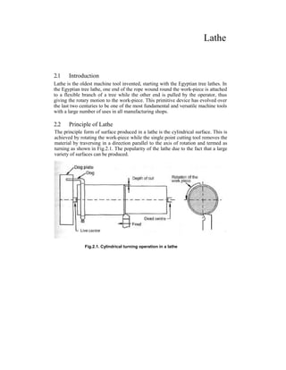
  • 1. Lathe 2.1 Introduction Lathe is the oldest machine tool invented, starting with the Egyptian tree lathes. In the Egyptian tree lathe, one end of the rope wound round the work-piece is attached to a flexible branch of a tree while the other end is pulled by the operator, thus giving the rotary motion to the work-piece. This primitive device has evolved over the last two centuries to be one of the most fundamental and versatile machine tools with a large number of uses in all manufacturing shops. 2.2 Principle of Lathe The principle form of surface produced in a lathe is the cylindrical surface. This is achieved by rotating the work-piece while the single point cutting tool removes the material by traversing in a direction parallel to the axis of rotation and termed as turning as shown in Fig.2.1. The popularity of the lathe due to the fact that a large variety of surfaces can be produced. Fig.2.1. Cylindrical turning operation in a lathe
  • 2. 2.2 2.3 Classification of Lathe Lathes of various designs and constructions have been developed to suit the various conditions of metal machining. But all types of lathes work on the same principle of operation and perform the same function. The types generally used are: i) Bench lathe 11J OUGGQ 13.1116 iii) Engine lathe iv) Tool room lathe v) Capstan and turret lathe vi) Automatic lathe vii) Special-purpose lathe. 2.3.1 Bench lathe It is a very small lathe and is mounted on bench or cabinet. It is used for small and; precision work since it is very accurate. It is usually provided with all the attachments and is capable of performing all the operations. 2.3.2 Speed lathe It is power driven simplest type of lathe mostly used for wood turning. Tools are hand operated. Cone pulley is the only source provided for speed variation of the spindle. 2.3.3 Engine lathe or center lathe It is a general-purpose lathe. It is normally used in all types of machine shops. It carries a great historical significance that in the very early days of the development of this machine it was driven by a steam engine. So it is called as engine lathe. The stepped cone pulley arrangement is often used for varrying the speed of the lathe spindle. The cutting tools are controlled either by hand or by power. 2.3.4 Tool room lathe It is nothing but the same engine lathe but equipped with certain extra attachments to make it suitable for relatively more accurate and precision type of work carried out in a tool room. 2.3.5 Capstan and turret lathes These are production lathes. Several tools are set on a revolving turret to facilitate in doing large number of operations on a job with the minimum wastage of time. 2.3.6 Automatic lathes These are high speed, heavy duty, mass production lathes with complete automatic control. They are so designed that all the working and job handling movements of
  • 3. Engine Lathe 2.3 the complete manufacturing process for a job are done automatically. After the job is completed, the machine will continue to repeat the cycles producing identical parts even with out the attention of an operator. Another variety of this type of lathes includes the semi-automatic lathes in which the mounting and removal of the work is done by the operator whereas all the operations are performed by the machine automatically. Automatic lathes are available having single or multi spindles. 2.3.7 Special-purpose lathes As the name implies, they are used for special purposes and for jobs, which cannot be accommodated for conveniently machined on a standard lathe. This category of lathes include such machines as crank shaft turning lathes, wheel lathe, canOshaft lathe, duplicating lathe, T-lathe and vertical lathe, Gap-bed lathe etc. 2.4 Constructional features of a engine lathe A typical engine lathe is shown in Fig.2.2. Fig.2.2. General view of a centre lathe showing various mechanisms and features
  • 4. 2.4 The headstock is towards the left-most end on the bed and is fixed to it, which houses the power source, the power transmission, gear box and the spindle. The spindle is hollow and is sufficiently rigid to provide accurate rotary motion and maintains perfect alignment with the lathe axis. A live centre fits into the Morse taper is the spindle hole for the purpose of locating the work piece axis. The main gear box provides the necessary spindle speeds considering the range of materials to be turned in the lathe. The headstock also houses the feed gear box to provide the various feed rates and thread cutting ranges. The tailstock is towards the right most end on the bed, which provides a tailstock spindle for the purpose of locating the long components by the use of centers. The tailstock is movable on the inner guide ways provided on the bed to accommodate the different lengths of work-pieces. It also serves the purpose of holding tools such as center drill, twist drill, reamer, and etc. for making and finishing and finishing holes in the components which are located in line with the axis of rotation. The third major element in the lathe mechanism is the carriage, which provides the necessary longitudinal motion to the cutting tool to generate the necessary surfaces. This also houses the cross-slide for giving the motion (cross feed) to the cutting tool in a direction perpendicular to the axis of rotation, the compound slide which provides an auxiliary slide to get the necessary special motion for specific surface generations and the tool post which allows for the mounting of the cutting tool. The motion from the spindle motor is communicated to the carriage through a lead screw. Engagement of the lead screw with the carriage is through the use of a half nut. Though the lead screw could be used for feeding the cutting tool in a direction parallel to the axis of rotating, many a time a separate feed rod is provided for this function. The main reason is that the lead screw is more accurate and is used only for thread cutting, such that it maintains its accuracy. 2.5 Description of various parts of lathe 2.5.1 BED It is supported on broad box-section columns and is made of cast iron. Its upper surface is either scraped or ground and the guiding and sliding surfaces are provided. The bed consists of two heavy metal slides running lengthwise, with ways or V's formed upon them. It is rigidly supported by cross girths. The outer guide ways provide bearing and sliding surface for the carriage, and the inner ways for the tailstock. Three major units mounted on bed are the headstock, the tailstock, and the carriage. The scraped or ground guiding and sliding surfaces on the lathe bed ensure the accuracy of alignment of these three units. The headstock is permanently fixed to the bed; the tailstock is adjustable for position to accommodate work-pieces of different lengths. The carriage can be traversed to and between the headstock and the tailstock either manually or by power. Lathe bed is made of high grade special cast iron having high vibration damping qualities. Lathe bed is secured rigidly over cabinet leg and end leg and all other parts are fitted on it (Refer Fig.2.3)
  • 5. Engine Lathe 2.5 Top surface of bed is machined accurately. The important considerations in design of lathe bed are its rigidity, alignment and accuracy. In its use, every care should be taken to avoid formation of scratches; nicks and dents by falling tools spanners and it should be lubricated regularly to avoid rusting. The lathe bed being the main guiding member for accurate machining work, it should be sufficiently rigid to prevent deflection under cutting forces: should be designed to resist the twisting stresses set up due to resultant of two forces: should be seasoned naturally to relive the stresses set up during casting. Fig.2.3 Fig.2.4 (a) shows a section through a typical lathe bed. It may be noted that while top surfaces take the weight of the headstock, Carriage and tailstock, narrow surfaces like 'G' act as guiding surfaces for movement of carriage and tailstock. Fig.2.4 (b) shows some alternative arrangements of guides and supports. It is important to note that guiding surfaces should not be too far apart to avoid cross-wind or jamming effect. Fig.2.4 (a) Section through lathe bed
  • 6. Fig.2.4 (b) Alternative arrangements of guides on lathe bed 2.5.2 Headstock It supports the main spindle in the bearings and aligns it properly. It also houses necessary transmission mechanism with speed changing levers to obtain different speeds cone pulley or gears or combination of both could be used to change speed of spindle. Accessories mounted on head stock spindle: 1) Three jaw chuck 2) Four jaw chuck 3) Lathe center and lathe dog 4) Collect chuck 5) Face plate 6) Magnetic chuck. The complete head stock consists of the headstock casting which is located on the ways of the bed at the lift side of the operator, the hollow spindle in which the live center is rigidly held by a taper and the necessary gears and mechanisms for obtaining the various spindly speeds. The centerline of the headstock is parallel to the guide ways, in both horizontal and vertical planes. All the modern lathe employ all-geared headstock. However, where greater simplicity and low cost are the criteria, cone-drive headstock can be used. A geared headstock may be driven either direct from a line shaft or from an independent motor, the drive being transmitted to the constant speed main drive pulley. Headstock also incorporates the self-contained clutch and brake mechanism by which the pulley may be coupled to the starting in the headstock as required. Usually arrangements are provided so that when the pulley is running free the spindle is braked automatically sliding gearing is generally employed for obtaining the various speed changes, the gears being mounted on multi spindle shafts and traversed axially thereon by external control levers through selector mechanism. 2.6
  • 7. Engine Lathe 2.7 A separate speed change gearbox is placed below headstock to reduce the speed in order to have different feed rates for threading and automatic lateral movements of carriage. The feed shaft is used for lost turning operations and lead screw is used for cutting threads etc. 2.5.3 Main Spindle It is a hollow cylindrical shaft and long slender jobs can pass through it. The spindle end facing the fail stock is called the spindle nose. The spindle nose has a more taper hole (Self-locking taper) and threads on outside. The morse taper is used to accommodate lathe center or collet chuck and threaded portion for chuck or face plate. The design of the lathe spindle and its bearings forms important feature, as the thrust of the cutting tool tends to deflect the spindle. Fig.2.5. Main Spindle Anti friction bearings are used in the headstock, and the spindle, which is made of high-tensile steel suitably hardened and tempered, is supported in roller bearings. The front spindle bearings take both the axial and radial loads on the spindle and the rear bearing is so designed that the spindle may float axially from the front bearings to allow the expansion and contraction. The front bearing is made adjustable by a flanged plate and is preloaded in assembly to avoid any possibility of slackness during the cut, with consequent vibration. Fig.2.6. Schematic sketch of lathe The spindle nose is designed for rapid mounting and removal of chucks and fixtures on it, and also for positioning them accurately and securely. For this purpose,
  • 8. 2.8 screwed type spindle nose with two locating cylindrical surfaces in front and rear, and threads in between is used. The overhang of the spindle nose is kept to minimum to guard against bending. The spindle is made hollow to allow long bars to pass through. On the front side, it has a taper socket to mount a live center, which rotates with the spindle. The various face plates and chucks are secured to the flange of the spindle nose by bolts or studs, and positioned by taper spigot. 2.5.4 Tailstock It is movable casting located opposite to the headstock on the ways of the bed. It is used for two purposes, (i) to support the other end of the work when being machined, and (ii) to hold a tool for performing operations like drilling, reaming, taping etc. it contains the dead centers the adjusting screw and the hand wheel. The body of the tailstock is adjustable on the base which is mounted on the guide ways of the bed and can be moved to and fro. The object of making the body adjustable on the base is to provide means for lining up the center, carried in the moving spindle, with the headstock center, or for offsetting this center to permit tapers to be turned. Axial adjustment of the dead center in the movable spindle in the tailstock body is provided for by means of a hand-wheel, which is attached to a screw engaging the nuts in the rear of the movable spindle. It can be located by any position in the body by means of a lever. The spindle is bored or ground to a taper gauge to take center which may be of the fixed or revolving type. Fig.2.7. Tailstock Fig.2.7 shows sketch of tailstock. Tailstock spindle 4 is displayed in body 1 by turning screw 5 with the hand wheel 7. Spindle is fixed in position by operating lever 3. The spindle carries a taper-shank center 2. The tailstock is moved along the machine's slide ways by hand or with the aid of the saddle. The tailstock can be
  • 9. Engine Lathe 2.9 locked with lever 6, which is connected to the rod 8 and lever 9. Clamping pressure can be adjusted with nut 11 and screw 12. Greater force in clamping can be exerted with nut 13 and screw 14 which holds lever 10 against the bed. 2.5.5 End of bed Gearing The motion of the headstock spindle is also transmitted to the feed gear box through the gearing at the end of the bed. The drive is than transmitted through the feed gear box: selectively to the lead screw or the feed shaft, depending on whether the machine is being used for screw cutting of plane turning. The position of end of bed gearing ensures a constant relationship between the traverse speed of the carriage and the spindle speed, irrespective of how the latter may be varied. Provision is also made for reversing the direction on the traverse of the carriage at the end of the bed gearing. The traverse rate of carriage on the bed gearing. The traverse rate of carriage on the bed is controlled by means of the gearing at the end of the bed in conjunction with the feed gear box. Most of the latest types of lathes have the reversing mechanism built into the headstock and actuated by means of a separate lever. In certain lathes, the lead screw and feed shaft may be run, constantly in one direction, and the reversal of the saddle traverse is obtained by means of reverse gearing in the apron. The changes in the feed rate normally required for turning or threading can be made in the feed gear box, but when special threads have to be cut, it may be necessary to alter the ratio of gearing at the end of the bed. 2.5.6 Carriage (Fig.2.8) Fig.2.8. Carriage It is located between the headstock and tailstock. It is fitted on the bed and slides along the bed guide ways and can be locked on the bed at any desired position by tightening the carriage lock screw. It can be moved manually with a hand wheel or with power feed.
  • 10. 2.10 It consists of following 5 main parts 1) Saddle 2) Cross slide 3) Compound rest consisting of a swivel and top slide 4) Tool post 5) Apron. 2.5.7 The apron (Fig.2.9) It is fastened to the saddle and hangs over the front of the bed. It contains the gears and clutches for transmitting motion from the feed rod to the carriage, and the split nut, which engages with the lead screw during cutting threads. It converts the rotary motion of the feed shaft or the lead screw to a translator motion of the carriage longitudinally on the bed or at the cross slide transversely on the carriage. The lead screw is coupled to the carriage by means of a split nut fixed in the apron, and the feed shaft generally drives the carriage through worm gearing. Two types of aprons are extensively used, one type incorporating drop worm mechanism and the other friction or dog clutches. The apron is fitted to the front position of the saddle facing the operator. It consists of a hand wheel for saddle movement, pinion to engaged with the rack for saddle movement, a lever to engage the automatic feed for the saddle automatic feed clutch, split nut (half nut) and lead screw. It houses control of carriage and cross slide. It contains controls to transmit motion from the feed rod or lead screw to the carriage and the cross slide. It houses gears, levers, hand wheels and clutches to operate-the carriage by hand or by automatic power feed. A lever is provided to engage the split nut for cutting the thread. 2.5.8 Saddle (Fig.2.10) It is made up at a H shaded casting Generally it has a V guide and a flat guide on one side for mounting it on the lathe bed guide ways. It also aids the saddle to slide along the bed guide ways by operating a hand wheel; The other side of a saddle is provided with a male dovetail to accommodate the cross slide with a jib. Fig.2.10. Saddle Fig.2.9. Apron
  • 11. Engine Lathe 2.11 2.5.9 Compound Rest (Fig.2.11) It supports the tool post and cutting tool in its various positions. It may be swiveled on the cross-slide to any angle in the horizontal plane: its base being graduated suitably. A compound rest is necessary in turning angles and boring short tapers and forms on forming tools. 2.5.10 Cross slide (Fig.2.12) It provided with a female dovetail on one side and assembled on the top of the saddle with its male dovetail. A tapered gib is provided between the saddle and cross slide dovetails to permit required fit for movement of cross slide on saddle. Top surface of cross slide is provided with T slots to enable fixing of rear tool post or coolant attachment. Front side is graduated in degrees to facilitate swiveling of the compound rest to the desired angle. Fig.2.12. Cross slide Compound rest consists of swivel and top slide and is mounted on the cross slide. Swivel is directly assembled on the cross slide and can be swiveled on either side to give the desired angle to the compound rest. It is provided with a male dovetail on the top surface. Top slide is provided with a female dovetail and is assembled on the swivel with a tapered job for adjustments. Top slide can be made to slide on the swivel by a precision screw rod and is moved manually. With the help of the top slide, the tool post can get horizontal, perpendicular, or angular movements to one axis of the bed guide ways depending upon the position of the swivel. Fig.2.11. Compound rest Fig.2.13. Assembly of cross slides and saddle
  • 12. 2.12 2.5.11 Tool post It is used to hold various cutting tool holders. The holders rest on a wedge which is shaped on the bottom to fit into a concave-shaped ring (segmental type), which permits the height of the cutting edge to be adjusted by tilting the tool (Refer Fig.2.14) It is fixed on the top slide. It gets its movement by the movement of the saddle, cross slide and top slide. Three types of tool posts care commonly used. 1) Ring and rocker tool post. 2) Quick change tool post 3) Square head tool post Ring and rocker tool post consists of a circular tool post with a slot for accommodating the tool or tool holder, a ring a rocker and a tool clamping screw one side of the ring is flat and other side is spherical on which the rocker sits. The tool is clamped on the rocker. The height of the tool tip can be adjusted with the help of the ring and rocker arrangement. Four way tool post has provision for holding four separate tool holders, which may be swiveled to a variety of positions. The square-turret type tool holder is illustrated in Fig.2.15. Tapered arbor 3 with a threaded end is Fig.2.14 secured in the locating bore of top slide 5. Square turret 6 is fitted over the taper, on turning handle 4 clock wise its boss 2 goes down on the thread of arbor 3 end exerts pressure through spacer 1 and thrust bearing on the turret, making it sit tight on the taper. When being tightened, the turret is held against rotation by a ball, which is jammed between the surfaces formed by a slot on the arbor base and a hole in the turret. To change the position of the tool, handle 4 is turned counterclockwise. Boss 2 goes up the thread of arbor 3, releasing turret 6. At the same time boss 2 turns turret 6 by means of friction elements, which engage the annular recess on the underside of the boss. The friction elements are fastened to the turret by pins 7. The spring-loaded ball, which is forced into its hole, does not prevent the turret from turning. If handle 4 takes an inconvenient position when tightened, the necessary adjustment can be made by changing the thickness of spacer 1. 2.5.12 Overload safety devices Important parts of lathe like gears, feed screws lead screws may get overloaded due to one reason or other. Shear pins and slip clutches are used to prevent damage by overloading. A shear pin is designed to be of a particular diameter and shape and can withstand a particular torque. When the machine motion stops.
  • 13. Engine Lathe 2.13 Fig.2.15. Tool holder A slip clutch also protects the feed rod and connecting mechanisms. It is designed to release the feed rod when a specific force is exceeded. It also permits the feed rod to be automatically re-engaged when the force is reduced. 2.6 Lathe specifications In order to specify a lathe, a number of parameters could be used based on the specific application. However, the major elements used for specification should invariably be based on the components that would be manufactured in the lathe. Fig.2.16. Capacity specifications for a lathe Thus the following are the basic elements generally specified for the capability of the lathe machine (Fig. 2.16) 1) Distance between centers-this would be specifying the maximum length of the job that can be turned in the lathe. 2) Swing over the bed-this specifies the maximum diameter of the job that can be turned in the lathe machine, generally restricted to small length jobs. 3) Swing over the cross slide-this specifies the maximum diameter of the job that can be turned in the lathe diameter of the job across the cross slide, which is generally the case.
  • 14. 2.14 Though the above gives the basic capacity of the machine as shown in fig.2.16, There are a number of other factors that should also be specified to fully describe the lathe machine. They are: 1) Horse power of the motor 2) Cutting speed range 3) Feed range 4) Screw cutting capacity 5) Accuracy achievable 6) Spindle nose diameter and hole size. Typical specifications of some center lathes are given in table 2.1 Table.2.1 specifications of engine lathes Center height, mm 250, 300 375, 450 525, 600 750, 900 Bed width, mm 325, 375 450, 550 650, 750 900, 1050 Sizes available, mm 1650 to 4200 2400 to 9600 2400 to 9600 2400 to 9600 Distance between centers (mm) 500 to 3100 1000 to 8200 800 to 8000 mm 800 to 8000 mm Power capacity, H.P 3 5 7.5/10 10/15 Spindle speed range 30 to 550 30 to 350 15 to 200 15 to 200 Further specification would be based on the accessories used with the machine tool and their respective capabilities. 2.7 Operations performed in a engine lathe 2.7.1 Turning Turning is the most generally used operation in a lathe. In this the work held in the spindle is rotated while the tool is fed past the work-piece in a direction parallel to the axis of rotation. The surface thus generated is the cylindrical surface as shown inFig.2.1. 2.7.2 Facing Facing is an operation for generating flat surfaces in lathes as shown in fig.2.17. The feed in this case is given in a direction perpendicular to the axis of revolution. The tool used should thus have an approach angle suitable so that it would not interfere with the work-piece during the tool feeding.
  • 15. Engine Lathe 2.15 Fig.2.17. Facing The-radius of work-piece at the contact point of tool varies continuously as the tool approaches the center and thus the resultant cutting speed varies in facing starting at the highest value at the circumference to almost zero near the center. Since the cutting action and the surface finish generated depend upon the actual surface, the finish becomes very poor as the tool approaches the center. While choosing the rotational speed of the work-piece due to care has to be taken of this fact. 2.7.3 Knurling Knurling is a metal working operation done in a lathe. In this a knurling tool having the requisite serrations is forced ori the work-piece material, thus deforming the top layers as shown in Fig.2.18. This forms atop surface which is rough and provides a proper gripping surface. Fig.2.18. Knurling
  • 16. 2.16 2.7.4 Parting Parting and grooving are similar operations. In this a flat nosed tool plunge cuts the work-piece with a feed in the direction perpendicular to the axis of revolution as shown in Fig.2.19. This operation is generally carried out for cutting off the part from the parent material. When the tool goes beyond the center, the part would be severed. Other wise a rectangular groove would be obtained. It is also possible in similar operations to use a special form of tool to obtain the specific groove shape. Fig.2.19. Parting tool in operation 2.7.5 Drilling Drilling is the operation of making cylindrical holes in to the solid material as shown in Fig.2.20. A twist drill is held in the quill of the tailstock and is fed in to the rotating work-piece by feeding the tailstock quill. Since the work-piece keeps rotating, the axis of the hole is very well maintained, even when the drill enters at an angle initially. The same operation can also be used for other hole making operations such as center drilling counter sinking and counter boring. The operation is limited to holes through the axis of rotating of the work-piece and from any of the ends. Fig.2.20. Drilling operation in a lathe
  • 17. Engine Lathe 2.17 2.7.6 Boring Boring is the operation of enlarging a hole already made by a single point boring tool termed as boring bar as shown in Fig.2.21. The operation is somewhat similar to the external turning operation. However, in view of the internal operation. The tool used is less rigid compared to the turning tool and as a result it cannot with- stand the large cutting forces. Thus the process parameters used are some that lower than those used for turning. Boring is used for generating an accurate hole with good surface finish. Fig.2.21. Boring operation in a lathe 2.8 Work holding devices The work holding devices normally used should have the following provisions: 1) Suitable location 2) Effective clamping, and 3) Support when required. 2.8.1 Chucks The most common form of work holding device used in a lathe is the chuck. Chucks come in various forms with varying number of jaws. 2.8.1.1 3-jaw chuck 3-jaw chuck or the self-centring chuck as shown in fig.2.22. is the most common one. The main advantage of this chuck is the quick way in which the typical round job is cent red. All the three jaws mesh with the flat scroll plate. Rotating the scroll plate through a bevel pinion moves all the three jaws radialy inward or out ward by the same amount. Thus the jaws are able to center any job whose external locating surface is cylindrical or symmetrical, like hexagonal. Through it is good for quick centering it has limitations in terms of the gripping force accuracy, which is gradually lost due to the wearing of the mating parts. 2.8.1.2 4-jaw chuck The independent jaw chuck has four jaws, which can be moved in their slots, which are independent of each other (fig.2.23), thus clamping any type of configuration.
  • 18. 2.18 Fig.2.22. Schematic layout of a three-jaw chuck Since each of these jaws can be moved independently any irregular surface can be effectively centred. Better accuracy in location can be maintained because of the independent movement. However more times is spent in fixturing a component in a 4-jaw compared to the 3-jaw chuck. This is generally used for heavy work-pieces and for any configuration. Fig.2.23. Schematic layout of a four-jaw chuck The jaws in a 4-jaw chuck can be reversed for clamping large diameter work-piece as shown in Fig.2.24. The soft jaws are sometimes used in these chucks for clamping surface of a component whose surface is.already finished and which is likely to be disfigured by the hard surface of the normal jaws used in them. 2.8.2 Centres The three-jaw and four-jaw chucks are normally suitable for short components. However along component supporting at only one end would make it to deflect under the influence of the Fig.2.24. Chuck and reverse jaw usage
  • 19. Engine Lathe 2.19 cutting force. In such cases the long work-piece ends are provided with a centre hole as a shown in Fig.2.25. Through these centre holes the centers mounted in the spindle and the tailstock would rigidly locate the axis of the work-piece. Fig.2.25. Centre hole locating between centres Centres as shown in fig.2.25 would be able to locate the central axis of the work- piece, however would not be able to transmit the motion to the work-piece from the spindle. For this purpose, generally a carrier plate and dog as shown in Fig.2.26. would be used. The centre located in the spindle is termed as live canter while that in the tailstock is termed the dead centre. The shank of the center is generally finished with a morse a taper, which fits into the tapered hole of the spindle or tailstock. The live centre rotates which the work-piece and hence it remains soft. The dead centre does not rotate, and hence it is hardened as it forms the bearing surface. However, in case of heavier work-piece the relative movement between the work- piece and the dead centre causes a large amount of heat generated. In such cases, a revolving centre is used. In this the centre is mounted in a roller bearing and it thus rotates freely, reducing the heat generated at the tailstock end. In cases where a facing operation is to be carried out with centres, a half centre is sometimes used. Fig.2.26. Dog carrier and revolving centre, half centre, steady
  • 20. 2.20 Some of the precautions to be observed during the use of centres are: 1) The centre hole in the work must be clean and smooth and have an angle of 60° bearing surface, large enough to be consistent with the diameter of the work. For heavier work this may be made 75° to 90°. 2) The bearing must take place on the countersunk surfaces and not on the bottom of the drilled hole. 2.8.3 Steady When the job becomes very long, then it is likely to deflect because of its owr weight as well as due to the cutting force acting away from the supports provided at both the maximum deflection point. Sometimes a steady is fixed to the carriage, so that it moves with the tool, thus effectively compensating for the acting cutting force. 2.8.4 Faceplate Fig.2.27. Fixturing using a face plate for odd shaped parts For odd shaped components a faceplate is more widely used where the locating and clamping surfaces need not be circular. This has radial slots on the plate as shown in Fig.2.27, for the purpose of locating the component and clamped by means of any standard clamps. The method is somewhat similar to the clamping of work-piece on a milling machine table using the T-slots on the table. However, in view of the fact
  • 21. Engine Lathe 2.21 that the faceplate rotates, the component is likely to be off centre. This would cause vibrations due to the mass unbalance. A balancing mass would therefore have to be provided as shown in Fig.2.27. Sometimes angle plates along with the faceplate may have to be used for typical components where the locating surface is perpendicular to the plane of the plate as shown in fig.2.27. 2.8.5 Mandrels For holding components with locating holes for the purpose of generating external surfaces, a mandrel is generally used. Various types of mandrels used are shown in Fig.2.28. Fig.2.28. Types of mandrels used for work holding The above types of work holding devices are more useful for general-purpose work. However, for production work using the above work holding devices would lead to considerable time being spent in locating and holding individual work-pieces. In production machine tools it is therefore necessary to use work-holding devices, which require very less time for clamping purpose. A collet is one such device, which provides good clamping accuracy with very little time required for clamping and unclamping. 2.8.6 Collet chuck A collet has a sleeve as the holding part, which is slit along the length at a number of points along the circumference as shown in fig.2.29. When uniform pressure is applied along the circumference of the sleeve, these segments elastically deflect
  • 22. 2.22 and clamp the component located inside. Since the deflection of the sleeve is in the elastic range, it springs back once the clamping pressure is removed, thus releasing the component located inside. This clamping method is very accurate and fast in operation and holds the work uniformly over the entire circumference. However, the size range in which a collet becomes operation is very small in view of the limit on the elastic deformation allowed. Thus a large number of chucks need to be main- tained in the inventory to the variety of diameters to be worked in the machine tool. This is normally used for large-scale production where saving in terms of the locat- ing and clamping time is desirable. Fig.2.29. Collet chuck principle 2.9 Taper turning methods Cutting tapers on a lathe is a common application. A number of methods are available for cutting tapers in a lathe. They are: 1) Using a compound slide 2) Using form tools 3) Offsetting the tailstock' 4) Using taper turning attachment. The compound slide is an auxiliary slide underneath the tool post and above the carriage. It is possible to swivel the compound slide to the desired angle of the taper as shown in fig.2.30 for cutting the tapers. The tool is then made perpendicular to the work-piece and feed is given manually by the operator. Some of the features of this method are: 1) Short and steep taper can be easily done. 2) Limited movement of the compound slide. 3) Feeding is by hand and is non-uniform. This is responsible for low productivity and poor surface finish.
  • 23. Engine Lathe 2.23 Fig.2.30. Compound slide method for taper turning Another method that is normally used for production applications is the use of special form tool for generating the tapers as shown in Fig.2.31. The feed is given by plunging the tool directly into work. This method is useful for short tapers, where the steepness is of no consequence such as for chamfering when turning long tapers with form tools, the tool would likely to chatter (Vibrate) resulting in poor surface finish. However care of the form tools . « . _ . . . . .. , , r .j. Fig.2.31. Taper turning using forms tools. particularly for regrinding is a careful exercise. The cutting edge should be perfectly straight for good accuracy. Fig.2.32. Tail stock offset.
  • 24. 2.24 Another method used is that of offsetting the tailstock from the centre position, By offsetting the tailstock, the axis of rotation of the job is inclined by the half angle of taper as shown in Fig.2.32. The feed to the tool is given in the normal manner parallel to the guide ways. Thus the conical surface is generated. Refer to Fig.2.32, the offset can be calculated as follows: S = AB Since = L Sina If ais very small, then we can be approximate This is the most general situation where the taper is to be obtained over a small portion of the length 1 of the job while the actual length of the work piece L could be long. However when they are equal If L = 1, Then The offset'S' that is possible would generally be limited, and as such this method is suitable for small tapers over a long length. The disadvantage is that the centres would not be properly bearing in the centre holes and as such there would be non- uniform wearing. Example 2.1 Find the setting required for turning a taper of 85mm diameter to 75mm diameter over a length of 200mm, while the tool length of the job is 300mm between centres. Tailstock offset is to be used for generating the prescribed taper. Another method for turning tapers over a comprehensive range is the use of taper turning attachment. In this method a separate slide way is arranged at the rear of the cross slide. This slide can be rotated at any angle to be set up. The block that can slide in this taper slide way is rigidly connected to the cross slide as shown in Fig.2.33. The cross slide is made floating by disconnecting it from its lead screw. As the carriage moves for feeding the block moves in the inclined track of the slide, gets the proportional cross movement perpendicular to the feed direction and the cross slide and in turn the cutting tool gets the proportional movement. Thus the tool tip followed the taper direction set in the attachment. However, in this condition the cross slide cannot be used for normal turning operation.
  • 25. Engine Lathe 2.25 Fig.2.33. Taper turning attachment This method is commonly used for arrange of tapers. Setting of the cutting tool is most important, since the form of the taper cut would be affected by the position of the cutting tool with respect to the work-piece. For example, consider the case of a cutting tool set below the centre line of the work-piece as shown in fig.2.34. If the work-piece is to hove r as radius at the small end and R the radius at the big end with L as the length of the taper, the original taper angle a to be produced is given by Fig.2.34. Possible error in taper turning using taper turning attachment because of wrong positioning of the cutting tool Where R = radius of the work at the big end
  • 26. 2.26 R = radius of the work at the small end L = length of the taper. If we consider a section along the length at a distance of x from the small end, the radius Y at that point is given by This can be rearranged as This is the equation of the taper being produced, which is a hyperbola. Thus the surface produced by a tool located away from the centre is hyperboloid. To find the taper angle, we may calculate the radius at the big end for a corresponding small end diameter r as follows. From Fig OC2 = OE2 + CE2 = OE2 + (CD + DE)2 Since OC = OB = radius of big end, AB = OB -r The taper angle generated is given by tana = — Example 2.2 While turning a taper using taper turning attachment the setting is done for 4°, but the tool is set 3mm below the centre. If the work-piece at the small end is 40mm, calculate the actual taper produced. The taper angle is 4°, and the big end of the work-piece considering the length of the taper is 100mm. R = 100 tan 4 = 6.9927mm = 725.44
  • 27. Engine Lathe 2.27 = 26.933mm The produced taper angle is there fore The error produced is Error in half taper = 4-3.9697 = 0.0303° = 2' 2.10 Thread cutting methods Cutting screws is another important task carried out in lathes. A typical form is shown in Fig.2.35. There are a large number of thread forms that can be machined in a lathe such as whit worth, acme, ISO metric, etc. Fig.2.35. Simple thread definition Thread cutting can be considered, as turning the path to be travelled by the cutting tool is helical. However there are some major differences between turning and thread cutting, while in turning the interest is in generating a smooth cylindrical surface, in thread cutting the interest is in cutting a helical thread of a given form and depth which can be calculated from different forms of threads as given in table.2.2.
  • 28. 2.28 Table.2.2: Formula for some common thread forms Thread form Formula for calculating the parameters British standard whit worth (BSW) Depth = 0.6403 x pitch Angle = 55° in the plane of the axis Radius at the crest and root = 0.137329 xpitch British association (BA) Depth = 0.6 x pitch Angle = 47.5° in the plane of the axis Radius at the crest and 2 x pitch root = ] ( International standards organization (ISO) metric thread Max. Depth = 0.7035 x pitch Min.Depth = 0.6855 x pitch Angle = 60° in the plane of the axis Root radius: Maximum =0.0633 x pitch Minimum - 0.054 x pitch American standard ACME Height of thread = 0.5 x pitch + 0.254 mm Angle = 29° in the plane of the axis Width at tip = 0.3707 x pitch Width at root = 0.3707 x pitch-0.132mm The shape of the cutting tool is the same form as the thread; the feed is given by the lead screw. Feed is same as the lead of the pitch to be generated. In the normal turning the thickness of the uncut chip is same as the feed rate chosen, whereas in the thread cutting case it is controlled by the depth of cut d, in view of the thread form being generated as shown in Fig.2.36 (a). The uncut chip thickness tu can be shown to be Tu = 2 x d x tan ^ The depth of cut in the case of thread cutting can be given in two ways, i.e. component cutting as in Fig.2.36 (a) or plunge cutting as shown in Fig.2.36 (b). Fig.2.36. Depth of cut in screw cutting In the case of plunge cutting, the cutting of the thread takes place along both the flanks of the tool. This means that the cutting tool will have to be provided with a zero or negative rake angle. In addition the relief along the cutting edge cannot be
  • 29. Engine Lathe 2.29 provided in view of the form to be achieved. Cutting takes place along a longer length of the tool. This gives rise to difficulties in machining in terms of higher cutting forces and consequently chattering (violent vibrations). This results in poor surface finish and lower tool life, thus this method is not generally preferred. With the compound feeding, the tool needs to be moved in the both the directions along the bed as well as a direction perpendicular to it simultaneously to position the tool tip along one flank of the thread. The configuration helps in a smooth flow of chips as the cutting takes place only along one cutting edge. This method thus more preferred to the earlier method. The only problem is to move the tool for giving the depth of cut along the flank of the thread, which can be achieved by the use of a compound slide for giving the depth of cut as shown infig.2.37. while the feed is given by the carriage in the conventional manner. Fig.2.37. Thread cutting using compound slide The compound slide is rotated by the half angle of the thread and the cutting tool is adjusted to make it perpendicular to the work-piece surface. For this purpose a thread setting gauge which contains the required form of the thread being cut is kept perpendicular to the surface of the work-piece and the tool tip is set as shown inFig.2.38. The next important consideration for thread cutting is the feeding of the tool along the helical path. For this purpose the lead screw is normally employed for feeding the tool along the length of the job. In turning, the engaging of the tool at any point would be of no consequence since the surface to be generated is cylindrical. However in thread cutting it is same thread profile generated in the first cut, other- wise no thread would be generated. One of the methods that can be followed in this case is to reverse the spindle while retaining the engagement between the tool and the work-piece. The spindle
  • 30. 2.30 reversal would bring the cutting tool to the starting point of the thread following the same path in reverse. After giving a further depth of cut the spindle is again reversed and the thread cutting is continued in the normal way. This is easy to work and is somewhat more time consuming due to the idle time involved in stopping and reversing of the spindle at the end of each stroke. Fig.2.38. Setting the cutting tool for thread cutting in a lathe Fig.2.39. Chasing dial principle It is also possible to cut threads on a tapered surface by combining the thread cutting concepts as explained above with the taper turning attachment as shown in Fig.2.40 Another method is to use a chasing dial to help in following the thread. As shown infig.2.39. The chasing dial consists of a worm gear located inside the carriage which is in mesh with the lead screw. A vertical shaft connected with the worm gear has a dial with separate markings to indicated equal divisions of the circumference lead screw which is in continuous engagement with the spindle, markings on its surface indicate the precise position of the thread being cut on the work-piece, thus it is possible to engage with the work-piece at any desired location.
  • 31. Engine Lathe 2.31 Fig. 2.40. Set-up for thread cutting on a taper 2.11 Tool Holders When the cutting tool is made of expensive material like high-speed steel, it is not necessary that the whole shank be made of same mate- rial. Instead the cutter can be made quite small and inserted in a holder. A common and useful type of tool holder for high-speed steel cutters is shown in Fig.2.41. it may be noted that it is also possible to adjusted the cutting edge for height without shifting the tool holder. The square hole in the nose holder to take the cutter is usually set and angle of 15-20° with the horizontal. A flat-faced cutter when in position will have an effective front rake equal to the angle of tool. The actual front clearance however will have to be increased in order to obtain the necessary effective front clearance. 2.12 Special Attachments Most of the details discussed so far allow for general-purpose machining operations to be carried using a centre lathe. In addition it is possible to provide special enhancements to the capability of a lathe where by it could be used for special application using special attachments one such attachment discussed earlier is the taper turning attachment for obtaining cylindrical tapers or conical surfaces.
  • 32. 2.32 2.12.1 Copy turning Attachment Sometimes there arises a need for machine complex contours, which require the feeding of the tool in two axes (X and Y) simultaneously, similar to taper turning. For such purpose copy turning a stylus, which can trace a master for the actual contour to be produced. The cross slide is made free similar to the taper turning attachment. 2.12.2 Radius turning attachment In this attachment the cross slide is attached to the bed by means of a radius arm whose length is same as the radius of the spherical component to be produced as shown in Fig 2.42. The radius arm tip traces a radius R as shown infig.2.42. Fig.2.42. Radius turning attachment 2.13 Types of tools used in engine lathes A large variety of tools are used in centre lathes in view of the large types of surfaces that are generated. The actual type of tool used depends upon the surface of job being generated as well as the work-piece. Fig.2.43 (a) Different kinds of tools used for external surfaces
  • 33. Engine Lathe 2.33 A variety of tools used for normal generation of external surfaces are shown in Fig. 2.4 3 (a). Similar tools are available for generating the internal surfaces as well. The choice of a particular tool depends upon the actual surface to be generated as shown in Fig.2.43 (b). Fig.2.43 (b) Different kinds of tools used for internal surfaces The tools have primary cutting edge by means of, which the direction of the movement of the tool for removing the metal is indicated. The direction is termed as right or left depending upon the movement direction the tool is termed right when it cuts during the movement towards the headstock. It is derived by the fact that when the right palm is placed on the tool, the direction of the thumb indicates the direction of tool motion similarly the left hand tool cuts during its motion in the direction of tailstock. Fig.2.44. Form tool types used in center lathes a) Circular form tool b) Straight forming tool
  • 34. 2.34 The variations in the type of tools are indicative of the variety of applications for which theses tools are used. A large variety is needed because of the large number of surfaces to be generated. For example, by the side cutting edge angle of the tool, it is possible to known the application of pockets for which the tool can be used. Similarly some tools are required for facing applications while others are used for boring. 2.14 Errors in tool setting The tool should be set exactly at the center of the work-piece for proper cutting. If the tool is kept below or above the work-piece, the tool geometry gets affected as shown in fig.2.45. For example if the tool is set at a position below the work-piece center by a distance, then the expected changes are Fig.2.45. Tool setting errors The above angle decreases the actual rake angle a while the clearance angle increases by the same amount. Thus the cutting forces increase because of the reduction in the rake angle. Setting the tool above the center causes the rake angle to increase, while the clearance angle reduces. This leads to more rubbing, which takes place in the flank face. The following example shows the magnitude of error that is involved in a cutting tool setting. Example 2.3 While turning a diameter of 90mm, the turning tool is set below the centerline by an amount equal to 5mm. Find out the change in the effective cutting tool geometry. Where R is the actual radius of the component produced and r is the radius set
  • 35. Engine Lathe 2.35 If the actual back rank is 10°, the effective rake angle would be (10-6.38) = 3.62°. Similarly if the clearance angle is 5°, the effective clearance angle would be (5+6.38) = 11.38°. If the tool is set at a point above the centre line, there would be a corresponding increase in the rakd angle by the same amount, while the cleatance angle would be (5-6.38) = -1.38°, which would cause rubbing (interference) with the work-piece. 2.15 Machining time and power estimation Table.2.3: Suggested Cutting Process Parameters for Turning High speed steel tool Carbide tool Speed Feed Speed Feed Work material Hardness BHN m/min mm/rev m/min mm/rev Gray cast iron 150-180 30 0.25 140 0.30 Gray cast iron 220-260 20 0.25 90 0.30 Malleable iron 160-220 33 0.25 50 0.25 Malleable iron 240-270 - - 45 0.30 Cast steel 140-180 40 0.25 150 0.30 Cast steel 190-240 26 0.25 125 0.30 C20 steel 110-160 40 0.3.0 150 0.38 C40 steel 120-185 30 0.30 145 0.38 C80 steel 170-200 26 0.30 130 0.30 Alloy steel 150-240 30 0.25 110 0.38 Alloy steel 240-310 20 0.25 100 0.38 Alloy steel 315-370 15 0.25 85 0.25 Alloy steel 380-440 10 0.20 75 0.25 Alloy steel 450-500 8 0.20 55 0.25 Tool steel 150-200 18 0.25 70 0.25 Hot work die steel 160-220 25 0.25 120 0.25 Hot work die steel 240-375 15 0.25 75 0.25 Hot work die steel 515-560 5 0.20 23 0.20 Stainless steel 160-220 30 0.20 120 0.25 Stainless steel 300-350 14 0.20 70 0.25 Stainless steel 375-440 10 0.20 30 0.25 Aluminum alloys 70-105 210 0.30 400 0.38 Copper alloys 120-160 200 0.25 300 0.25 Copper alloys 165-180 85 0.25 230 0.25 To estimate the machining times, it is necessary to select the proper process parameters. For this purpose it is necessary to known the work-piece material and the cutting tool material combinations to arrive at the right combination of the process parameters, cutting speed, feed and depth of cut their choice is somewhat difficult and a lot depends upon the shop practices as well as experience of the operator/ planner.
  • 36. 2.36 Some typical values of these parameters are given in table for the materials that are generally used. These should be considered as starting values and should be modified further, based on shop experience. Some of the problems that are likely to be noticed during machining process are identified and shown in table with the possible causes. If any of these problems are observed during actual machining, the operator should take care of it by solving the root problem. Table.2.4: possible causes for turning problems. Observed problem Possible cause Vibration Work or chuck out of balance. Chatter Work improperly supported Feed rate too high. Tool overhang too large Tool is not properly ground or length of tool edge contact is high. Work-piece not turned Headstock and tailstock centers not aligned straight Work improperly supported Tool not in the center Work-piece out of Work loose between centers round Centers are excessively worn Center out of round 2.15.1 Turning The cutting speed in turning is the surface speed of the work-piece. Thus (2.1) where V = Cutting speed (Surface), m/min D = diameter of the work piece, mm N = rotational speed of the workpiece, rpm The diameter D to be used can be either the inital diameter of the blank or the final diameter of the workpiece after giving the depth of cut. However, there is practically not much change in the values obtained by using either of the values. To be realistic, the average of the two diameters would be better. From the above equation, we get (2.2) The rpm obtained from the previous equation may not be an exact value of the speed available on the lathe machine, since any lathe would only have limited range of rpms available. It is therefore necessary to adjust the value so obtained to that available in the speed range considering the work and tool material combination. This is demonstrated later using an example.
  • 37. Engine Lathe 2.37 (2.3) where L = length of the job, mm L0 = over travel of the tool beyond the lenght of the job to help in the setting of the tool, mm / = feed rate, mm/rev The over travel to be provided depends upon the operator's choice but usual values could be 2 to 3 mm on either side. The number of passes required to machine a component depends upon the left over stock (stock allowance). Also depending upon the specified surface finish and the tolerance on a given dimension, the choice would have to be made as to the number of finishing passes (I or 2) while the rest of the allowance is to be removed through the roughing passes. The roughing passes P. is given by (2.4) Where A = total machining allowance, mm A, = finish machining allowance, mm dr = depth of cut in roughing ,mm The value calculated from the above equation is to be rounded to the next integer. Similarly the finishing passes, P. is given by (2.5) Where dr = depth of cut in finishing, mm Example. 2.4 Estimate the actual machining time required for the component (C40 steel) shown inFig.2.46. The available spindle speeds are 70,110,176, 280, 440, 700, 1100, 1760, and 2800. Use a roughing speed of 30m/min at d finish speed of 60 m/min. The feed for rough- ing is 0.24 mm/rev while that for finishing is 0.10 mm/rev. The maximum depth of the cut for roughing is 2mm. Finish allowance may be taken as 0.75 mm. Blank to be used for machining is 50mm in diameter. Fig.2.46. Machining time
  • 38. 2.38 Metal Cutting & Machine Tools Stock to be removed = = 4mm Finish allowance == 0.75mm. Roughing Roughing stock available = 4-0.75 = 3.25mm. Since max.depth of cut to be taken is 2 mm, there are two roughing passes. Given cutting spend V = 3 0 m/min Average depth of cut = = 46 mm Spindle speed N = = 207.56 RPM The nearrst RPM available from the list is 176 RPM as 280 is very high compared to 207 as calculated. Machining time for one pass = = 2.898 minutes. Finishing Given cutting speed V =60 m/min Spindle speed N = = 439.05 RPM The nearst RPM available from the list is 440 RPM Machining time for one pass = = 2.77 minutes Total machining time = 2 x 2.888 + 2.77 = 8.546 minutes. Facing In facing the choice of the spindle speed is affected by the fact that the cutting tool is engaged with the work-piece at gradually changing radius. As a result the actual cutting speed is changing from the highest value at the surface to almost zero at the
  • 39. Engine Lathe 2.39 center. Thus the diameter used for calculating the rpm in Eq.2.3. Should be the average of blank diameter and the lowest diameter (Zero in case of complete facing) of the face being generated. TaperTurning The time calculation of taper turning depends upon the method used for the purpose. In the case of taper turning attachment, the calculation is similar to turning as the feed motion is given by the carriage parallel to the axis of rotation. However, when the tailstock off set method is used, the motion of the tool is parallel to the actual taper surface generated and that length should be used in Eq.2.4. All the other operations are similar to turning where care has to be taken to find the actual distance traveled in the operation. Example.2.5 In Fig.2.47 a component to be machined from a stock of CRS C40 steel, 40 mm in diameter and 75 mm long is shown. Calculate the machining times required for completing the part with (a) HSS tool and (b) carbide tool. Fig.2.47. Machining time The machining is to be carried out in two stages as pockets marked in Fig (b) as 1 and 2. Pocket-1: HSS Tool Assume cutting speed V = 30 m/min Feed rate/ =0.30 mm/rev Depth of cut = 2 mm Spindle speed = = 265.25 RPM = 265 RPM Time for machining one pass = = 0.9686 mintues
  • 40. 2.40 Metal Cutting & Machine Tools Number of passes required = = 2 Carbide Tool Assume cutting speed, V =145 m/min Feed rate/ =0.38 mm/rev Depth of cut = 2 mm Spindle speed = = 1282.05RPM = 1280 RPM Time for machining one pass = = 0.158 mintues Pocket-2: HSS Tool Number of passes required = = 2.5 «3 Spindle speed = = 353.677 RPM «355 RPM Time for machining one pass = = 0.394 mintues Carbide Tool Spindle speed = = 1709.44 RPM « 1710 RPM Time for machining one pass = = 0.065 mintues
  • 41. Engine Lathe 2.41 Total machining time For HSS tool 2 x 0.9686 + 3 x 0.394 = 3.1192 minutes For carbide tool 2 x 0.158 + 3 x 0.065 - 0.511 minutes The above gives only the estimation of actual machining time taken by the machine (tool in contact with the workpiece). In addition to this there are certain other times, often termed as idle times, associated with machining which have to be estimated, some representative values of these elemental times are given in table Table.2.5: Idle time elements for lathe. Time element Weight Time seconds Load and unload between centers with dog carrier with a work-piece Load and unload in a 3-jaw chuck with a work-piece weight lkg 2 kg 4 kg 8 kg lkg 2 kg 4kg 8 kg 20 30 40 50 30 40 50 60 Start/stop spindle Reverse spindle Change speed Change feed Engage/disengage feed Index tool post Approach tool, set to mark, return in turning Approach tool, set to mark, return in boring Move cross slide up to 100 mm Move saddle up to 150 mm Move saddle up to 500 mm Fit/remove tool in tailstock Approach/ remove tailstock Advance/return tail stock quill up to 50 mm 2 2 3 4 1 2 3 5 6 3 6 10 15 8 2.15.2 Power required in turning The power required at the spindle for turning depends upon the cutting speed, depth of cut, feed rate and the work piece material hardness and machinability. The power required depends upon the cutting force to be a power function of feed rate, f and depth of cut d, However, for the sake of gross estimation it can be safely assumed that cutting force F = k x d x f.
  • 42. 2.42 Table. 2.8: Constant K for power calculation Material being cut K (N/mm2 ) Steel, 100-150 BHN 1200 Steel, 150-200 BHN 1600 Steel, 200-300 BHN 2400 Steel, 300-400 BHN 3000 Cast iron 900 Brass 1250 Bronze 1750 Aluminium 700 Then power P =F x V combing the abive two equations, power P = k x d x f x v . Example.2.6 Calculate the power required for Touching and finishing passes in example Roughing Given feed rate/ = 0.24 mm/rev Depth of cut d = 2 mm Cutting speed V = = 25.43 m/min The value of k from table = 1600 N/mm2 Power = = 325.5 w = 0.326 kw Finishing Given feed rate/ =0.10 mm/rev Depth of cut d =0.75 mm Cutting speed V = = 60.13 m/min Power = = 120.26 w = 0.120 kw
  • 43. Engine Lathe 2.43 Example.2.7 Calculate the power required for roughing and finishing passes in Example Pocket 1: HSS Tool Assume cutting speed, V = 30 m/min Feed rate/ =0.30 mm/rev Depth of cut = 2 mm The value of from table = 1600 N/mm2 Power = = 480 w = 0.48 kw Carbide Tool Assume cutting speed, V =145 m/min Feed rate/ =0.38 mm/rev Depth of cut = 2 mm The value of from table = 1600 N/mm2 Power = = 2.939 w = 2.94 kw For the pocket also, the power required ramains the same since the processing parameters do not change. 2.16 Cutting Speed The cutting speed (V) of a tool is the speed at which the metal is removed by the tool from the work-piece. In a lathe it is the peripheral speed of the work past the cutting tool expressed in meters per minute. Cutting speed = (2.6) where d -> is the dinmeter of the work in mm,and n —» is the r.p.m. of the work. In the British system, cutting speed is expressed in feed per minute and dismeter of the work in inches. Cutting speed = (2.7)
  • 44. 2.44 Where d —»is the diameter of the work in inches, and n —> is the r.p.m. of the work. The cutting speed, directionof feed and depth of cut to be given to a workpiece are illustrated in Fig.2.48. 1. Diameter on which cutting speed is calculated, 2. Feed, 3. Depth of cut. Fig.2.48. Cutting speed, feed and depth of cut 2.17 Feed The feeds of a cutting tool in a lathe work is the distance the tool advances for each revolution of the work. Feed is expressed in millimeters per revolution. In the British system it is expressed in inches per revolution. Increased feed reduces cutting time. But increased feed greatly reduces the tool life. The' fed depends on factors such as size, shape, strength and method of holding the component, the tool shape and its setting as regards overhang, the rigidity of the machine, depth of cut, power available,etc..Coarser feeds are used for roughing and finer feeds for finishing cuts. 2.18 Depth of cut The depth of cut (t) is the perpendicular distance measured from the machined surface to the uncut surface of the work piece. In a lathe the depth of cut is expressed as follows: (2.8) Where, c/7 = diameter of the work surface before machining, and d2 = diameter of the machined surface. Other factors remaining constant, the depth of cut varies inversely as the cutting speed. For general purpose, the ratio of the depth of cut to the feed varies from 10:1