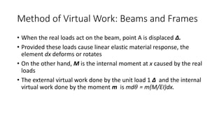
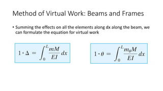
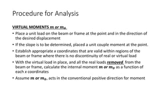
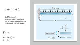
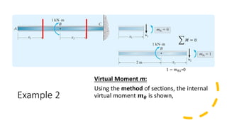
The document discusses the method of virtual work as applied to beams and frames for solving deflection and displacement problems. It outlines the processes for analyzing virtual moments and real moments using specific coordinates and provides examples for calculating vertical displacement, slope, and horizontal displacement in beam and frame structures. Key procedures include applying virtual loads, determining internal moments, and using the virtual-work equation to solve for desired outcomes.


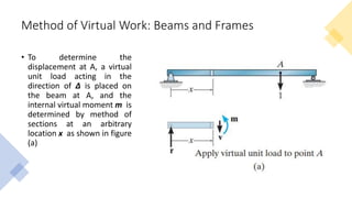


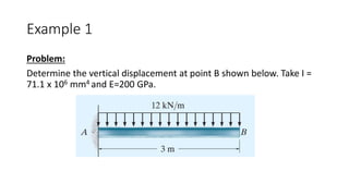


![Example 1
• Virtual-Work Equation:
Once m and M are determined, we can now apply the virtual-work
equation to solve for the displacement at B.
0
3
6𝑥3
𝐸𝐼
𝑑𝑥 =
6 3 4
4
− [
6(0)4
4
]](https://image.slidesharecdn.com/2022-02-22topic1methodofvirtualworkbeamsandframes-220620075841-2a0b5ff1/85/Topic1_Method-of-Virtual-Work-Beams-and-Frames-pptx-14-320.jpg)


![Geotechnical Engineering-II [Lec #9+10: Westergaard Theory]](https://cdn.slidesharecdn.com/ss_thumbnails/9-181020124827-thumbnail.jpg?width=640&height=640&fit=bounds)