Download as PDF, PPTX


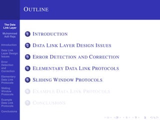
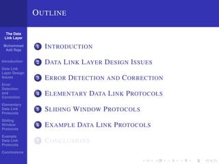
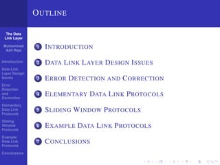
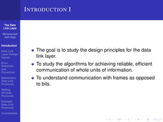
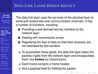
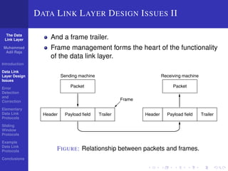
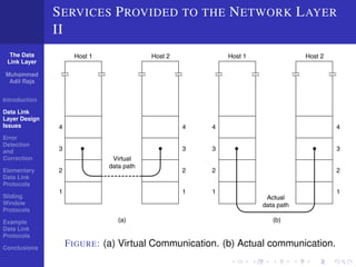
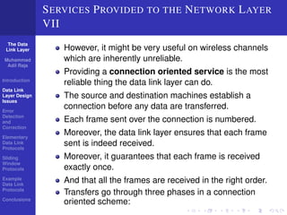
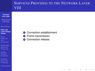
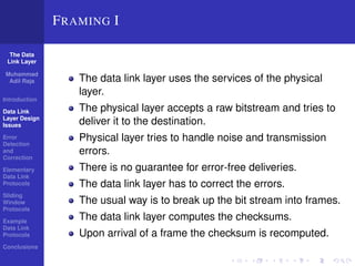
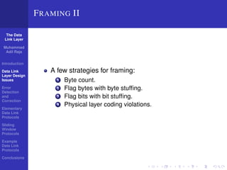
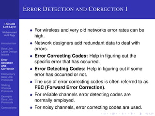
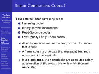
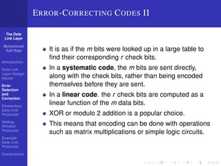
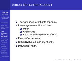
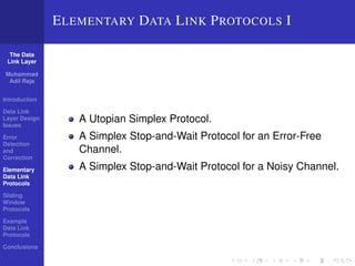
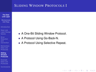

The document discusses the data link layer and outlines its key functions and design considerations. It covers three main services provided by the data link layer to the network layer: unacknowledged connectionless, acknowledged connectionless, and acknowledged connection-oriented. It also discusses framing of data, error detection and correction techniques, and elementary and sliding window protocols used at the data link layer. The goal is to study how the data link layer provides reliable and efficient communication between network layers on different machines.