This document discusses the design and analysis of air intake diffusers used in aircraft propulsion systems, focusing on the impact of geometry on flow uniformity and pressure recovery. It presents methodologies and computational fluid dynamics (CFD) tools utilized to model airflow inside a diffuser, highlighting the importance of minimizing turbulence and maintaining optimal air pressure at the engine compressor. The study emphasizes the design considerations necessary to optimize intake performance across various flight conditions.
![CFD Studies of Air Intake Diffuser
V. ANALYSIS
The analysis was carried out using CFX. In the Pre- processing the following boundary conditions were
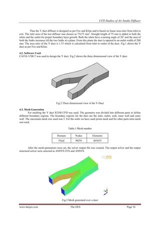
defined. First we tested the bare duct for zero angle of attack. The inlet velocity is 19.67m/s. in the second
module the angle of attack will be increased and tested. The simulation is started and the equations are solved
iteratively as a steady-state or transient. Finally a postprocessor is used for the analysis and visualization of the
resulting solution.
5.1. Boundary Conditions
Table.2.Boundary conditions
Inlet
Type
INLET
Location
INLET
Flow Regime
Subsonic
Heat Transfer
Static Temperature
Static Temperature
3.0000e+02 [K]
Mass And Momentum
Normal Speed
Normal Speed
1.9670e+01 [m s^-1]
Turbulence
Medium Intensity and Eddy Viscosity Ratio
Outlet
Type
OUTLET
Location
OUTLET
Flow Regime
Subsonic
Mass And Momentum
Average Static Pressure
Pressure Profile Blend
5.0000e-02
Relative Pressure
0.0000e+00 [Pa]
Pressure Averaging
Average Over Whole Outlet
Wall
Type
Location
SIDEWALL, WALL, INNERWALL
Heat Transfer
Adiabatic
Mass And Momentum
No Slip Wall
Wall Roughness
www.theijes.com
WALL
Smooth Wall
The IJES
Page 57](https://image.slidesharecdn.com/j030101053059-140222035348-phpapp01/85/J030101053059-5-320.jpg)
![CFD Studies of Air Intake Diffuser
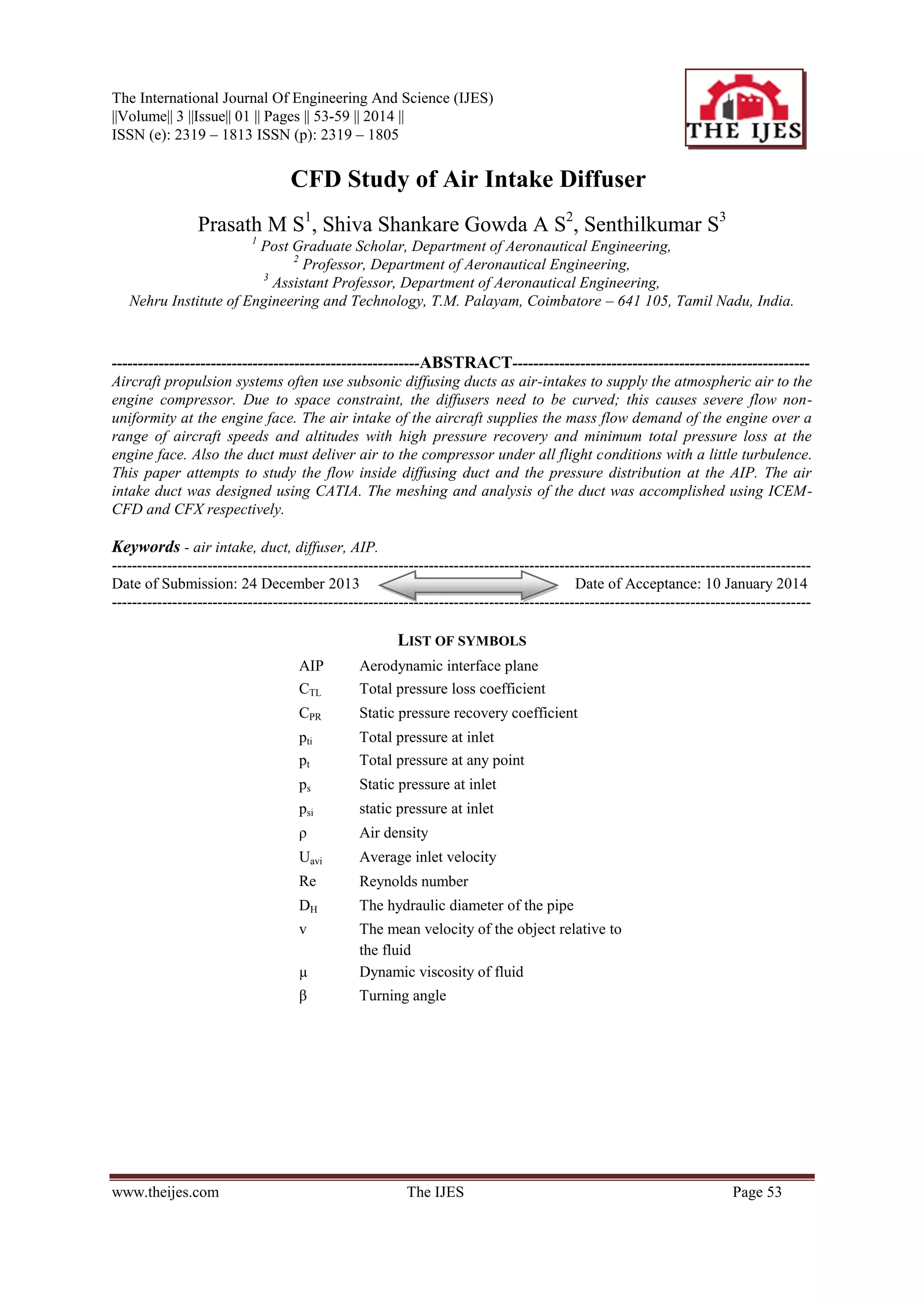
5.2. Domain
Table.3.Domain values
Fluid
Type
Fluid
Location
FLUID
Materials
Air Ideal Gas
Morphology
Continuous Fluid
Settings
Buoyancy Model
Non Buoyant
Domain Motion
Stationary
Reference Pressure
1.0000e+00 [atm]
Heat Transfer Model
Total Energy
Turbulence Model
k epsilon
5.3. Observation
From Fig.4 we can see flow separation occurring at the inflexion plane and turbulence at the diffuser
exit. The dark region in the Figure-4 shows the flow separation. Fig.5 shows non uniform flow at AIP. If this
flow is let into the compressor they damage the blades.
Fig.4. Bare duct showing flow separation
at the inflexion plane
Fig.5. Bare duct showing non uniform flow at AIP
VI. RESULTS AND SOLUTION
These vortices cause a decrease in the intake efficiency. The divergence of the duct allows the
separation point to shift further downstream. Shifting the separation point downstream enables the expanded
airflow to persist proportionality longer, the flow velocity at the separation point to become slower and
consequently the static pressure to become higher. The static pressure at the separation point governs over all the
pressures in the entire flow separation region. It shifts the separation point downstream therefore raises the
pressure of the flow separation region.
www.theijes.com
The IJES
Page 58](https://image.slidesharecdn.com/j030101053059-140222035348-phpapp01/85/J030101053059-6-320.jpg)
![CFD Studies of Air Intake Diffuser
REFERENCE
[1]
[2]
[3]
[4]
[5]
[6]
[7]
[8]
[9]
Abrahamsent.P.E.H, Pettersson Reifi. B.A, Szetrar. L, Fossdalt. J.B, “Air Intake Studies: Experimental measurements and
computational modelling”.
Akshoy Ranjan Paul, Pritanshu Ranjan, Vivek Kumar Patel, Anuj Jain, “Comparative Studies On Flow Control In Rectangular SDuct Diffuser Using Submerged-Vortex Generators”- Aerospace Science and Technology 28 (2013) 332–343.
R.W. Fox, and S.J. Kline, Flow Regimes in Curves Subsonic Diffuser. Trans ASME, Journal of Basic Engineering, Vol. 84, 1962,
pp. 303 – 316
Frederic Smith.C, Steve D. Podleskif, Wendy S. Barankiewicz and Susan Zeleznik.Z, “Comparison of F/A-18A Inlet Flow
Analyses with Flight Data Part 2”- Journal of Aircraft, Vol. 33, No. 3, May-June 1996.
Saha.K, Singh.S.N, Seshadri.V, and Mukhopadhyay.S, “Computational Analysis on Flow through Transition S-Diffusers: Effect
of Inlet Shape”- Journal of Aircraft, Vol. 44, No. 1, January–February 2007.
Stanley R. Mohler Jr, “Wind-Us Flow Calculations For The M2129 S-Duct Using Structured And Unstructured Grids”- (AIAA2004-0525)
Mattingly, J.D. (2006) „Elements of Propulsion : Gas Turbines and Rockets‟.
Oates, G.C. (1985) „Aerothermodynamics of Aircraft Engine Components‟.
Saravanamuttoo, Cohen, H., Rogers, GFC., HIH. (1996) „Gas Turbine Theory‟.
www.theijes.com
The IJES
Page 59](https://image.slidesharecdn.com/j030101053059-140222035348-phpapp01/85/J030101053059-7-320.jpg)


![Getting Started with Apache Spark: Big Data Made Simple [Free Meetup]](https://cdn.slidesharecdn.com/ss_thumbnails/apachesparkgettingstarted-260203175547-8361bcc3-thumbnail.jpg?width=640&height=640&fit=bounds)

