Download to read offline
![International Research Journal of Engineering and Technology (IRJET) e-ISSN: 2395-0056
Volume: 04 Issue: 11 | Nov -2017 www.irjet.net p-ISSN: 2395-0072
© 2017, IRJET | Impact Factor value: 6.171 | ISO 9001:2008 Certified Journal | Page 502
DESIGN & COMPUTATIONAL FLUID DYNAMICS ANALYSES OF AN
AXISYMMETRIC NOZZLE AT TRANSONIC FREE STREAM CONDITIONS
S Wasim Akram1, S. Rajesh2
1 M.Tech Student, Department of Mechanical Engineering, Krishna Chitanya Institute of Technology & Sciences,
Markapur.
2 Sr. Assistant Professor, Department of Mechanical Engineering, Krishna Chitanya Institute of Technology &
Sciences, Markapur.
---------------------------------------------------------------------***---------------------------------------------------------------------
Abstract - A numerical investigation of boat tail nozzle has
been carried out through computational software (GAMBIT
2.3.16, FLUENT 6.3). Effect of friction inadiabatic flowprocess
has studied and the friction factor is satisfactory level around
0.001452. A variation of cross sectional area with respect to
the corresponding Mach number relation output is achieved
through programming language (C++). Theisentropicprocess
of variable area nozzle and its flow properties such as mass
flow rate, total pressure, and free stream pressure are
calculated. Mach number = 0.8 (Transonic regime) analysis
have carried over modified cross sectional area of a throat
section in geometry which it is referred (Teryn 2003).
Throughout the investigation, validation work has done over
coefficient of pressure chart with the effective utilization of K-
epsilon turbulence model and its appropriate boundary
conditions. By the application wise, reduction of pressure loss
and improvement in design will suits the commercial jet
planes.
Key Words: boat tail nozzle, computational software
(GAMBIT 2.3.16, FLUENT 6.3)
1. INTRODUCTION
Computational fluid dynamics analyses of an axisymmetric
nozzle at transonic free stream conditions have been
completed to determine the capabilities of Reynolds
averaged navier stokes calculation to predict the details of
flow conditions in the propelleling jet which comes from
nozzle over external and internally. Pressure distribution of
the nozzle over internal and external is to be compared with
the standard data obtained in base reference [1].Before
proceeds about the system; fundamentals of nozzle and its
behavior are to be discussed in this chapter.
1.1 NOZZLE THEORY
Nozzle is a duct of varying cross sectional area used for
increasing the velocity of steadily flowingstreamoffluid.The
fluid enters the nozzle with a high pressure and relatively
small velocity. During the flow process, its pressure falls and
velocity increases continuously from entrance to exit of the
nozzle. The different expressions for the velocity of flows are
discussed in the following chapters. Types of nozzle are
converging or subsonic nozzle; the cross section of flow
region decreases continuously from entry to exit and the
acceleration of fluid is in the subsonic region, divergent
nozzle or supersonic nozzle; the flow passage diverges from
entry to exit and acceleration of fluid is in the supersonic
velocity range, convergent- divergent or delavel nozzle isthe
cross section of the flow passage converges down from entry
area to minimum area (throat area), and then diverges from
throat to exit. The flow velocity at the throat equals the sonic
velocity. But this boat tail nozzle is variable type.
The study of convergent- divergent type boat tail nozzle
has been investigated by reference [1]. Boat tail nozzle over
external and internal flow aerodynamic characteristics has
carried out in under grantNCC3–922andthatwassponsored
by the PropulsionResearchandTechnologyProjectofNASA’s
Next Generation Launch Technology Program.
Figure 1.1 schematic of NASA Langley experimental rig
(forebody/nozzle/support).
2. LITERATURE SURVEY
Teryn et.al. [1] Reported the Boat tail nozzle over internal
and external pressure distributionscomputed withtheWind
code have been compared with experimental data obtained
in the NASA Langley 16-Foot Transonic Tunnel. Using a
range of turbulence models, including the Explicit Algebraic
Stress model (EASM), the experimental data pressure
profiles on two nozzle geometries has been predicted
reasonably well.](https://image.slidesharecdn.com/irjet-v4i1187-171208092409/75/Design-Computational-Fluid-Dynamics-Analyses-of-an-Axisymmetric-Nozzle-at-Transonic-Free-Stream-Conditions-1-2048.jpg)
![International Research Journal of Engineering and Technology (IRJET) e-ISSN: 2395-0056
Volume: 04 Issue: 11 | Nov -2017 www.irjet.net p-ISSN: 2395-0072
© 2017, IRJET | Impact Factor value: 6.171 | ISO 9001:2008 Certified Journal | Page 503
The results show the greater pressure differences
between the jet and free stream flow appeared to improve
the EASM results. Values of free stream pressure, total
pressure and total temperature has been chosen by this
journal.
Oosthuizenet.al. [2] Formulated the formula for
Mass flow rate of convergent nozzle, divergent nozzle,
convergent divergent nozzle and variation ofarea nozzlei.e.,
isentropic variable area flow nozzle.
The adiabatic process of fluid flow with friction and
without friction is discussed and reasonably possible
conditions are stated for our problem. Programming codeof
adiabatic problem had taken by his book fundamental of
compressible flow.
Shames [3] discussed the fluid behavior in
compressible flows externally and internally also he stated
about the effects of friction at real situations around the
transonic Mach number variations in the throat section of
the nozzle.
3. OPERATING CHARACTERISTICS OF NOZZLE
3.1 CHARACTERISTICS OF NOZZLE
The effect of changes in upstream and downstream
pressures on the nature of the flow in and on the mass flow
rate through a nozzle .i.e., through a variable area passage
designed toaccelerateagasflow[2].Theupstreamstagnation
conditions, are kept constant while the conditions in the
downstream chamber into which the nozzle discharges are
varied. Therefore the pressureinthedownstreamchamberis
termed the back pressure. Asthe back pressureis decreased,
flow commences, this flow initially being subsonic
throughout the nozzle. Under these circumstances, the
pressure on the exit plane of the nozzle, remains equal to the
back pressureand mach number on the exitplaneislessthan
1.in this region of operation, a reduction in back pressure
produces an increase in the mass flow rate..
When the back pressurehasbeen decreased tothisvalue,
the mach number on the exit planemustbeequalto1.further
reduction in back pressure have no effect on the flow in the
nozzle. i.e., exit pressureisequaltocriticalpressure,themass
flow rate remains constant and the mach number in the exit
plane remains equal to 1.
Figure 3.1 Effect of back pressure in convergent nozzle
(Courtesy: Patrick H.Oosthuizen
Figure 3.2 Effect of back pressure on a) exit plane
pressure and b) mass flow rate through convergent nozzle.
3.2 NOZZLE PERFORMANCE CALCULATIONS
To find the stagnation condition of free stream surface and
nozzle jet:
-- (Eqn. 1)
-- (Eqn. 2)
-- (Eqn. 3)
-- (Eqn. 4)
-- (Eqn. 5)
-- (Eqn. 6)
Table -1:
PROPERTIES/PARAMETERS VALUES
Mach number 0.8
Total pressure 193Kpa
Total temperature 297K
Free stream pressure 66.6Kpa
Area of throat section 0.0762m
Mass flow rate 3.4444Kg/sec
Force/thrust 367.748KN
Table 3.1 Physical properties of nozzle condition.
3.3 REAL NOZZLE FLOW AT DESIGN CONDITION
OVER ADIABATIC FLOW WITH FRICTION
If M < 1, i.e., the flow is subsonic so decreasing the area
which increases the velocity and vice versa. If M > 1, i.e., the
flow is supersonic so, decreasing the area which decreases
the velocity and vice versa. If M = 1 dA/dV=0 and A reaches
the extremum, on that case A must be minimum.](https://image.slidesharecdn.com/irjet-v4i1187-171208092409/75/Design-Computational-Fluid-Dynamics-Analyses-of-an-Axisymmetric-Nozzle-at-Transonic-Free-Stream-Conditions-2-2048.jpg)
![International Research Journal of Engineering and Technology (IRJET) e-ISSN: 2395-0056
Volume: 04 Issue: 11 | Nov -2017 www.irjet.net p-ISSN: 2395-0072
© 2017, IRJET | Impact Factor value: 6.171 | ISO 9001:2008 Certified Journal | Page 504
But, only way to check out the Mach number variation by dA
is,
-- (Eqn.7)
From this eqn.7, it follows that
When M < 1, A increases and M decreases.
When M > 1, A increases and M increases.
When M = 1, dA = 0 i.e., A is minimum.
dA can also be 0 when dM is 0.
Therefore, a minimum in the flowarea canalsobeassociated
with a maximum or minimum in the mach number. Hence,
the effects of area change on the Mach number.
Table -2:
PARAMETERS VALUES
Wall shear 0
Viscosity of air 0.00001907
Frictional factor 0.001452
Table 3.2 variation of parameter value due to friction
4. COMPUTATIONAL INVESTIGATION:
Investigation were conductedwithCFDcodes(Gambit2.3.16
and Fluent 6.3), a general purpose tool which solves the
pressure based , implicit with absolute velocity formulation
and green gauss cell based node centered finite difference
approach. It is used for steady state calculations and utilize
second order upwind scheme. The solver was configured to
run with the following technical specifications: steady state
time stepping, two equation models K-epsilon and K-omega
with the necessity condition of perfect gas.
4.1 GEOMETRY DEFINITIONS AND BOUNDARY
CONDITIONS:
Fig -4.1: Geometrical configuration of nozzle.
2-Dimensional, structured, geometry and
computational grids were generated for all cases using
Gambit 2.3.16 software. In all cases, the nozzle is attachedto
a rear body of engine, whose geometry is included in the
computational models due to the well developed boundary
layers along the length of the body. The entire control
domain has a coordinates of (-15,-15) (45,-15) (45, 15)(-15,
15). The entire length assembly is 60cm; upstream nozzle
diameter is 7.0cm; exit nozzle diameter is 3.5cm; and the
variable throat diameter is 5.25cm; is 30cm locatedfromthe
mid of global co-ordinate system is shown in Figure 4.1.
a) Non-structured grids b) Structured grids
Figure.4.2 a) Structured and non-structured grids Grid
generation (structured and non-structured)
A grid dependence study was carried both
structurally and non-structurally and it is shown in fig 4.2.a,
b and c. The unstructured grid contained 30% more grid
points than structured mesh. Becauseoframregionininside
the nozzle i.e. throat section of the nozzle needs more grids
than other regions both externally and internally. For the
non- structured grids are more suitable for external flows
and in complex fluid problems but here the geometry is in
simple construction so we can avoid structured mesh and
considered only combined structured and unstructured
mesh for ease of solutions attaining. Here, we made 57,570
nodal points for reducing CPU memory consumption. And it
is sufficient to capture pressure distributions.
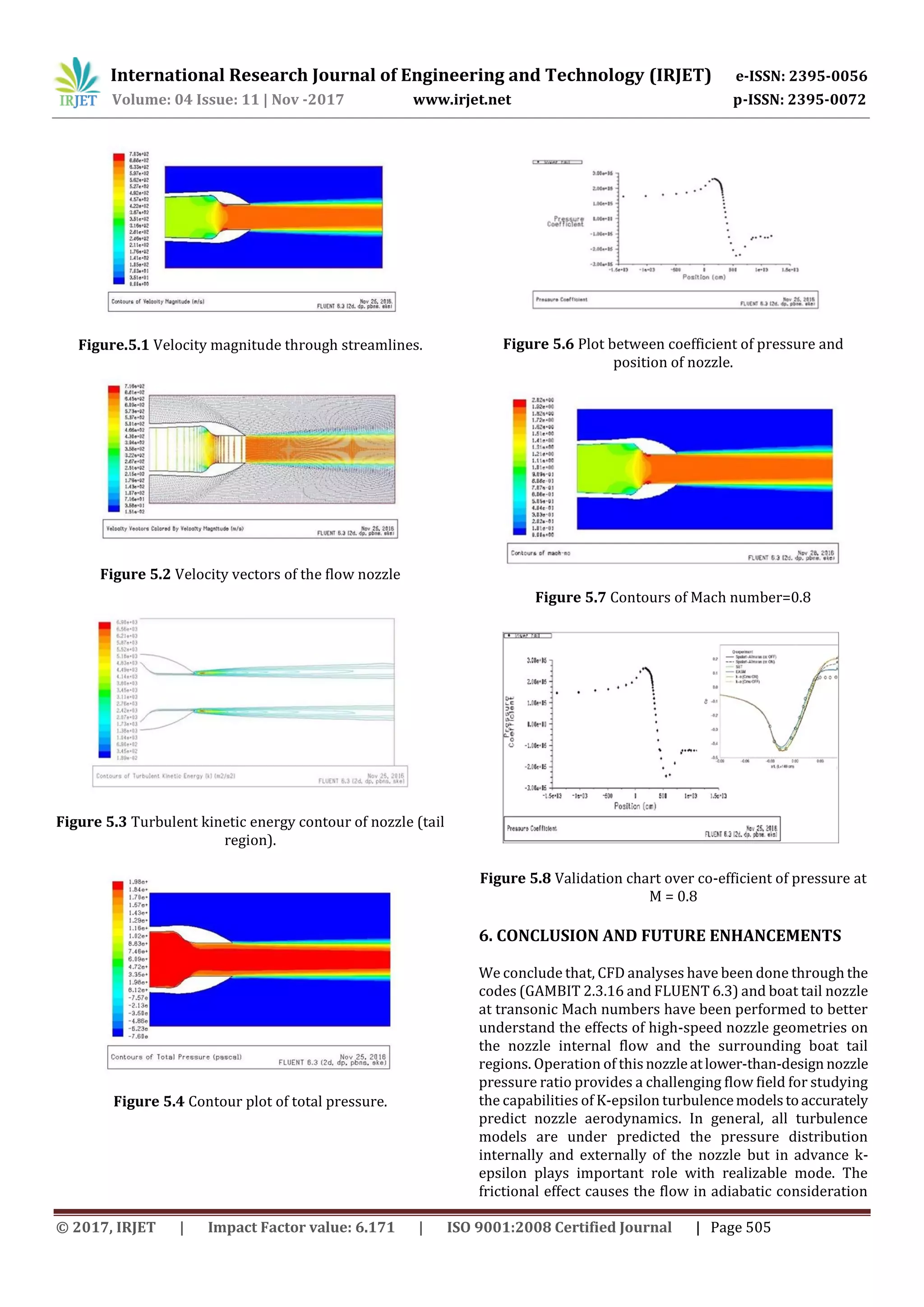
5. RESULTS AND DISCUSSION
Results are presented as contours of pressure distribution
on the internal and external nozzle surfaces, vector plot,and
coefficient of pressure plots over the flow field especially
with respect to distance (x/c). A variation of area is found to
decrease monotonically with Mach number variation as
discussed through programming code (C++). But in
reference [6], mass flow rate is found to decrease
monotonically with Mach number. Variation of static
pressure increases with Mach number less than 0.8 found to
be identical from inlet throat to exit for Mach number
greater than 0.8. Solutions are evaluated at specified nozzle
pressure ratio corresponds to mass flow rate, maximum
velocity, maximum pressure, and maximum thrust force.](https://image.slidesharecdn.com/irjet-v4i1187-171208092409/75/Design-Computational-Fluid-Dynamics-Analyses-of-an-Axisymmetric-Nozzle-at-Transonic-Free-Stream-Conditions-3-2048.jpg)
![International Research Journal of Engineering and Technology (IRJET) e-ISSN: 2395-0056
Volume: 04 Issue: 11 | Nov -2017 www.irjet.net p-ISSN: 2395-0072
© 2017, IRJET | Impact Factor value: 6.171 | ISO 9001:2008 Certified Journal | Page 506
i.e., real applications but it is considerably neglected in
isentropic flows. In isentropic flows, shocks are not induced
rapidly but that are consumed to be negligible and the
induction of shockwave may affect the flows entirely at any
transonic regime. In future, discussion of shockwaves,
separation of shockwaves and it’s control at same geometry
and transonic regime M=0.8 are to be analyzed with this
same CFD code.
REFERENCES
[1] “Computations of internal and external
axisymmetric nozzle aerodynamics at transonic speed” and
“computational study of axisymmetric nozzle through off
design performance” by Teryn Dalbello, NicholasGeorgiadis
and Dennis Yoder, Theo Keith, NASA/TM-2003-212731.
[2] “Compressible fluid flow” by Patrick H.Oosthuizen
and William E. Carscallen, McGraw-HILL INTERNATIONAL
EDITIONS 1997.Page no: 191-194 and 250-257.
[3] “Mechanics of fluids” by Irving H. Shames, McGraw-
HILL INTERNATIONAL EDITIONS 1992-498.
[4] “Fanning friction factor for pipe flow” by JIM
MCGOVERN, DUBLIN INSTITUTE OF TECHNOLOGY.
[5] “Modelingofturbulentflowsandboundarylayer” by
Dr.SrinivasaRao.P, C-Dac, India published in INTEC, Goatia,
January- 2010 Pp.420.
[6] “Flowanalysisofconvergent-divergent nozzleusing
CFD” by Gutty Rajeswararao and et.al, IJRME publication,
vol.1 october-december 2013, P p.136-144
BIOGRAPHIES
S Wasim Akram is currently
pursuing M.Tech in CAD/CAM at
Krishna Chaitanya Institute Of
Technology & Sciences, Markapur.
He received B.Tech degree in
Mechanical Engineering from Rao
and Naidu Engineering College
Ongole in the year 2013.
.
S. Rajesh working as Assistant
Professor in Krishna Chaitanya
Institute of Technology & Sciences,
Markapur.
He received M.Tech in Machine
Design from Rajeev Gandhi
Memorial college of Engineering
and Technology, Nandyal in the
year 2015.](https://image.slidesharecdn.com/irjet-v4i1187-171208092409/75/Design-Computational-Fluid-Dynamics-Analyses-of-an-Axisymmetric-Nozzle-at-Transonic-Free-Stream-Conditions-5-2048.jpg)

This document summarizes a numerical investigation of flow through an axisymmetric boat tail nozzle at transonic conditions using computational fluid dynamics (CFD). The study analyzed the effects of friction on adiabatic flow and determined a friction factor of 0.001452. CFD simulations using GAMBIT and FLUENT were conducted with a k-epsilon turbulence model to analyze pressure distributions, velocity vectors, and coefficient of pressure plots. Validation against experimental data showed reasonable agreement. The study concluded that CFD can predict nozzle aerodynamics, though turbulence models under predict pressures. Friction was found to impact real flows compared to isentropic assumptions. Future work could analyze shockwaves at Mach 0.8.