The document provides documentation for a quadcopter flight controller project using an Arduino Due and Kalman filters. It describes the author's process of setting up the Arduino Due in Atmel Studio instead of the Arduino IDE to better understand register settings. It details how to initialize various functions needed for the project, including uploading code, declaring pins, timers, I2C communication, UART, and interrupts. The author worked through issues with i2c communication and resetting, and provided code samples for initializing each required function.
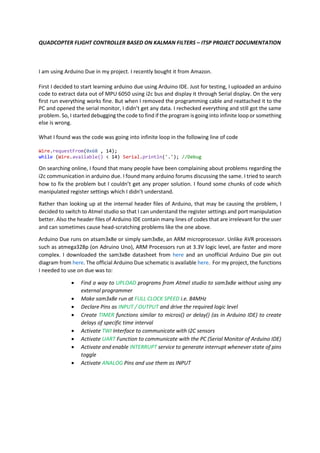
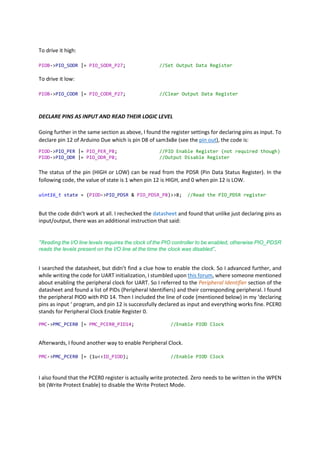
This Book helps the bargainer to getting started with avr studio and avr Micro controller interfacing. This book covers Navigating the AVR studio and many more avr interfacing examples
Join this video course on udemy . Click here :
https://www.udemy.com/course/mastering-microcontroller-with-peripheral-driver-development/?couponCode=SLIDESHARE
Learn bare metal driver development systems using Embedded C: Writing drivers for STM32 GPIO,I2C,SPI,USART from scratch
Software/Hardware used:
In this course, the code is developed such a way that, It can be ported to any MCU you have at your hand.
If you need any help in porting these codes to different MCUs you can always reach out to me!
The course is strictly not bound to any 1 type of MCU. So, if you already have any Development board which runs with ARM-Cortex M3/M4 processor,
then I recommend you to continue using it.
But if you don’t have any Development board, then check out the below Development boards.
A brief introduction to Arduino microcontroller platform hardware and programming for rapid prototyping, for more discussion and articles about different microcontroller platforms and tutorials please visit: http://elrayescampaign.blogspot.ca/
Join this video course on udemy . Click here :
https://www.udemy.com/course/mastering-microcontroller-with-peripheral-driver-development/?couponCode=SLIDESHARE
In this course, the code is developed such a way that, It can be ported to any MCU you have at your hand.
If you need any help in porting these codes to different MCUs you can always reach out to me!
The course is strictly not bound to any 1 type of MCU. So, if you already have any Development board which runs with ARM-Cortex M3/M4 processor,
then I recommend you to continue using it.
But if you don’t have any Development board, then check out the below Development boards.
This presentation is made as a part of our udemy course on STM32 MCUs and peripherals. The ppt covers STM32 Reset and Clock Control unit of the STM32 , different types of clock sources such as HSE (High Speed External crystal), HSI (Internal High Speed RC ), PLL concepts,HSI calibration , HCLK,PLCKx and others.
To enroll for our video courses on Microcontroller Programming, RTOS programming, Embedded linux, Bootloader development
visit here : www.fastbitlab.com
youtube : https://www.youtube.com/channel/UCa1REBV9hyrzGp2mjJCagBg
Best-embedded-corporate-training-in-mumbaiUnmesh Baile
Vibrant Technologies is headquarterd in Mumbai,India.We are the best Embedded System training provider in Navi Mumbai who provides Live Projects to students.We provide Corporate Training also.We are Best Embedded System Programming classes in Mumbai according to our students and corporators
CODE BLUE 2014 : A security assessment study and trial of Tricore-powered aut...CODE BLUE
ECU software is responsible for various functionality in the vehicle, e.g., engine control and driver assistance systems. Therefore, bugs or vulnerabilities in such systems may have disastrous impacts affecting human life. We consider possible vulnerabilities in ECU software categorized into memory corruption vulnerabilities and non-memory corruption vulnerabilities, and examine attack techniques for such vulnerabilities. Since we did not acquire and reverse-engineer actual ECU software, we first consider in theory how and if attacks are possible under the assumption that there would exist memory corruption vulnerabilities in ECU software. For our investigation, we consider the ECU microcontroller architecture TriCore1797 (TriCore Architecture 1.3.1) from Infineon which exists in a number of ECUs. In contrast to x86 architecture, the return address is not stored on the stack; therefore, we assumed that performing code execution by stack overflow would not be easy. We investigated if it would be possible to perform arbitrary code execution based on approaches from the PC environment and also if other attack approaches could be considered. We considered the following attack approaches:
1) Overwriting a function pointer stored on the stack by performing a buffer overflow to execute code;
2) Overwriting the memory area handling context switching used by TriCore itself to execute code;
3) Overwriting the vector tables used by interrupt and trap functions.
Moreover, using a TriCore evaluation board and software created to perform the experiments, we tested the various attack approaches. We confirmed that several attack approaches are not possible due to security mechanisms provided by the microcontroller or differences in the microcontroller architecture compared to traditional CPUs. However, under certain specific conditions, as a result of performing a buffer overflow attack to overwrite a function pointer, we manage to make the TriCore jump to an address of our choosing and execute the code already stored on that location.
A starter guide how to use Microchip MPLAB IDE for PIC microcontrollers and related tools like MPLAB C18, C30 and C32 compilers, and how to MPLAB features to get connected and integrated with programmer/debugger devices and development kits from Microchip.
for more discussion and articles about different microcontroller platforms and tutorials please visit: http://elrayescampaign.blogspot.ca/
It covers several topics: basics, drivers and shields, GPIO, compilers and IDEs, hradware protocols I2C, SPI, UART. The presentation also provides several examples: DC motor control, stepper motor control, reading analog data ADC, what is DMA and a music equalizer (both software and hardware).
Advanced View of Atmega Microcontroller Projects List - Projects Tutorials Co...WiseNaeem
Most of the electronics geeks are asking the whole list of Atmega AVR projects PDF here we will share list every month as our projects are being updated on daily basis.
Advanced View of Atmega Microcontroller Projects List - Projects Tutorials Co...WiseNaeem
Most of the electronics geeks are asking the whole list of Atmega AVR projects PDF here we will share list every month as our projects are being updated on daily basis
Advanced View of Atmega Microcontroller Projects List - ATMega32 AVR.pdfWiseNaeem
Most of the electronics geeks are asking the whole list of Atmega AVR projects PDF here we will share list every month as our projects are being updated on daily basis.
Advanced View of Atmega Microcontroller Projects List - ATMega32 AVR.pdfWiseNaeem
Most of the electronics geeks are asking the whole list of Atmega AVR projects PDF here we will share list every month as our projects are being updated on daily basis. PDF is a good source to work offline.
Contactless digital tachometer using microcontroller IJECEIAES
Tachometer is a device that used for counting or for the measuring purpose of the number of revolutions (that is the total number rotations made by the device in unit of measuring time) of an object in unit time. It is expressed in the unit of RPS or RPM, the model uses a set of infrared transducer receiver to count the RPM pulses, and the Arduino microcontroller is used for the implementation of the project. The individual pulses are counted by the microcontroller to give the final output of the RPM.
JMeter webinar - integration with InfluxDB and GrafanaRTTS
Watch this recorded webinar about real-time monitoring of application performance. See how to integrate Apache JMeter, the open-source leader in performance testing, with InfluxDB, the open-source time-series database, and Grafana, the open-source analytics and visualization application.
In this webinar, we will review the benefits of leveraging InfluxDB and Grafana when executing load tests and demonstrate how these tools are used to visualize performance metrics.
Length: 30 minutes
Session Overview
-------------------------------------------
During this webinar, we will cover the following topics while demonstrating the integrations of JMeter, InfluxDB and Grafana:
- What out-of-the-box solutions are available for real-time monitoring JMeter tests?
- What are the benefits of integrating InfluxDB and Grafana into the load testing stack?
- Which features are provided by Grafana?
- Demonstration of InfluxDB and Grafana using a practice web application
To view the webinar recording, go to:
https://www.rttsweb.com/jmeter-integration-webinar
DevOps and Testing slides at DASA ConnectKari Kakkonen
My and Rik Marselis slides at 30.5.2024 DASA Connect conference. We discuss about what is testing, then what is agile testing and finally what is Testing in DevOps. Finally we had lovely workshop with the participants trying to find out different ways to think about quality and testing in different parts of the DevOps infinity loop.
Connector Corner: Automate dynamic content and events by pushing a buttonDianaGray10
Here is something new! In our next Connector Corner webinar, we will demonstrate how you can use a single workflow to:
Create a campaign using Mailchimp with merge tags/fields
Send an interactive Slack channel message (using buttons)
Have the message received by managers and peers along with a test email for review
But there’s more:
In a second workflow supporting the same use case, you’ll see:
Your campaign sent to target colleagues for approval
If the “Approve” button is clicked, a Jira/Zendesk ticket is created for the marketing design team
But—if the “Reject” button is pushed, colleagues will be alerted via Slack message
Join us to learn more about this new, human-in-the-loop capability, brought to you by Integration Service connectors.
And...
Speakers:
Akshay Agnihotri, Product Manager
Charlie Greenberg, Host
UiPath Test Automation using UiPath Test Suite series, part 4DianaGray10
Welcome to UiPath Test Automation using UiPath Test Suite series part 4. In this session, we will cover Test Manager overview along with SAP heatmap.
The UiPath Test Manager overview with SAP heatmap webinar offers a concise yet comprehensive exploration of the role of a Test Manager within SAP environments, coupled with the utilization of heatmaps for effective testing strategies.
Participants will gain insights into the responsibilities, challenges, and best practices associated with test management in SAP projects. Additionally, the webinar delves into the significance of heatmaps as a visual aid for identifying testing priorities, areas of risk, and resource allocation within SAP landscapes. Through this session, attendees can expect to enhance their understanding of test management principles while learning practical approaches to optimize testing processes in SAP environments using heatmap visualization techniques
What will you get from this session?
1. Insights into SAP testing best practices
2. Heatmap utilization for testing
3. Optimization of testing processes
4. Demo
Topics covered:
Execution from the test manager
Orchestrator execution result
Defect reporting
SAP heatmap example with demo
Speaker:
Deepak Rai, Automation Practice Lead, Boundaryless Group and UiPath MVP
Neuro-symbolic is not enough, we need neuro-*semantic*Frank van Harmelen
Neuro-symbolic (NeSy) AI is on the rise. However, simply machine learning on just any symbolic structure is not sufficient to really harvest the gains of NeSy. These will only be gained when the symbolic structures have an actual semantics. I give an operational definition of semantics as “predictable inference”.
All of this illustrated with link prediction over knowledge graphs, but the argument is general.
Dev Dives: Train smarter, not harder – active learning and UiPath LLMs for do...UiPathCommunity
💥 Speed, accuracy, and scaling – discover the superpowers of GenAI in action with UiPath Document Understanding and Communications Mining™:
See how to accelerate model training and optimize model performance with active learning
Learn about the latest enhancements to out-of-the-box document processing – with little to no training required
Get an exclusive demo of the new family of UiPath LLMs – GenAI models specialized for processing different types of documents and messages
This is a hands-on session specifically designed for automation developers and AI enthusiasts seeking to enhance their knowledge in leveraging the latest intelligent document processing capabilities offered by UiPath.
Speakers:
👨🏫 Andras Palfi, Senior Product Manager, UiPath
👩🏫 Lenka Dulovicova, Product Program Manager, UiPath
State of ICS and IoT Cyber Threat Landscape Report 2024 previewPrayukth K V
The IoT and OT threat landscape report has been prepared by the Threat Research Team at Sectrio using data from Sectrio, cyber threat intelligence farming facilities spread across over 85 cities around the world. In addition, Sectrio also runs AI-based advanced threat and payload engagement facilities that serve as sinks to attract and engage sophisticated threat actors, and newer malware including new variants and latent threats that are at an earlier stage of development.
The latest edition of the OT/ICS and IoT security Threat Landscape Report 2024 also covers:
State of global ICS asset and network exposure
Sectoral targets and attacks as well as the cost of ransom
Global APT activity, AI usage, actor and tactic profiles, and implications
Rise in volumes of AI-powered cyberattacks
Major cyber events in 2024
Malware and malicious payload trends
Cyberattack types and targets
Vulnerability exploit attempts on CVEs
Attacks on counties – USA
Expansion of bot farms – how, where, and why
In-depth analysis of the cyber threat landscape across North America, South America, Europe, APAC, and the Middle East
Why are attacks on smart factories rising?
Cyber risk predictions
Axis of attacks – Europe
Systemic attacks in the Middle East
Download the full report from here:
https://sectrio.com/resources/ot-threat-landscape-reports/sectrio-releases-ot-ics-and-iot-security-threat-landscape-report-2024/
GraphRAG is All You need? LLM & Knowledge GraphGuy Korland
Guy Korland, CEO and Co-founder of FalkorDB, will review two articles on the integration of language models with knowledge graphs.
1. Unifying Large Language Models and Knowledge Graphs: A Roadmap.
https://arxiv.org/abs/2306.08302
2. Microsoft Research's GraphRAG paper and a review paper on various uses of knowledge graphs:
https://www.microsoft.com/en-us/research/blog/graphrag-unlocking-llm-discovery-on-narrative-private-data/
Key Trends Shaping the Future of Infrastructure.pdfCheryl Hung
Keynote at DIGIT West Expo, Glasgow on 29 May 2024.
Cheryl Hung, ochery.com
Sr Director, Infrastructure Ecosystem, Arm.
The key trends across hardware, cloud and open-source; exploring how these areas are likely to mature and develop over the short and long-term, and then considering how organisations can position themselves to adapt and thrive.
Key Trends Shaping the Future of Infrastructure.pdf
Itsp documentation quadcopter flight controller based on kalman filters
1. QUADCOPTER FLIGHT CONTROLLER BASED ON KALMAN FILTERS – ITSP PROJECT DOCUMENTATION
I am using Arduino Due in my project. I recently bought it from Amazon.
First I decided to start learning arduino due using Arduino IDE. Just for testing, I uploaded an arduino
code to extract data out of MPU 6050 using i2c bus and display it through Serial display. On the very
first run everything works fine. But when I removed the programming cable and reattached it to the
PC and opened the serial monitor, I didn’t get any data. I rechecked everything and still got the same
problem. So, I started debugging the code to find if the program is going into infinite loop or something
else is wrong.
What I found was the code was going into infinite loop in the following line of code
Wire.requestFrom(0x68 , 14);
while (Wire.available() < 14) Serial.println('.'); //Debug
On searching online, I found that many people have been complaining about problems regarding the
i2c communication in arduino due. I found many arduino forums discussing the same. I tried to search
how to fix the problem but I couldn’t get any proper solution. I found some chunks of code which
manipulated register settings which I didn’t understand.
Rather than looking up at the internal header files of Arduino, that may be causing the problem, I
decided to switch to Atmel studio so that I can understand the register settings and port manipulation
better. Also the header files of Arduino IDE contain many lines of codes that are irrelevant for the user
and can sometimes cause head-scratching problems like the one above.
Arduino Due runs on atsam3x8e or simply sam3x8e, an ARM microprocessor. Unlike AVR processors
such as atmega328p (on Adruino Uno), ARM Processors run at 3.3V logic level, are faster and more
complex. I downloaded the sam3x8e datasheet from here and an unofficial Arduino Due pin out
diagram from here. The official Arduino Due schematic is available here. For my project, the functions
I needed to use on due was to:
• Find a way to UPLOAD programs from Atmel studio to sam3x8e without using any
external programmer
• Make sam3x8e run at FULL CLOCK SPEED i.e. 84MHz
• Declare Pins as INPUT / OUTPUT and drive the required logic level
• Create TIMER functions similar to micros() or delay() (as in Arduino IDE) to create
delays of specific time interval
• Activate TWI Interface to communicate with I2C sensors
• Activate UART Function to communicate with the PC (Serial Monitor of Arduino IDE)
• Activate and enable INTERRUPT service to generate interrupt whenever state of pins
toggle
• Activate ANALOG Pins and use them as INPUT
2. And the following points are why I need them in my project. Some of them are obvious, so I marked
them obvious.
• UPLOAD: Obvious.
• FULL CLOCK SPEED: The faster, the better off course.
• INPUT / OUTPUT: Obvious.
• TIMER: Obvious.
• TWI: Most of the sensors in my project use I2C Interface.
• UART: To print data in the Serial Monitor and to talk with the GPS.
• INTERRUPT: To read receiver signals while flying.
• ANALOG: To determine battery voltage while flying.
FIND A WAY TO UPLOAD PROGAMS FROM ATMEL STUDIO WITHOUT EXTERNAL PROGRAMMER
Arduino Due has two ports: The Programming Port (ATMEGA16U2) and the Native USB Port (SAM3X).
At first, I tried to copy the way Arduino IDE uploads the program to atsam3xe via Programming Port
(Atmega16U2). I checked the “Show Verbose Output during Upload” of the Arduino IDE and copied
the “Commands and Arguments” to create a new external tool in the Atmel Studio. Although it worked
for Arduino Uno and Leonardo (AVR Processor based boards), it didn’t work for Arduino Due. I am not
mentioning the exact way I did it, as it didn’t work anyway. What I learnt was: just like ‘avrdude.exe’
is required to program AVR Processors, ‘bossac.exe’ is required to program ARM Processors.
As I couldn’t figure out how to upload code via Programming Port, I switched to Native USB Port. I
found this website which neatly describes how to upload via Native USB Port. I followed the steps and
it worked just fine.
MAKE SAM3X8E RUN AT 84MHz
On creating a new project on Atmel Studio and selecting device as sam3x8e, in the main program, a
function called SystemInit() was called by default. On searching what it does, I found that it
configures the system to run at 84MHz. The code in the declaration of SystemInit() is well
commented and can be easily understood by referring the datasheet.
DECLARE PINS AS OUTPUT AND RUN REQUIRED LOGIC LEVEL
Going through the datasheet, under section 31. Parallel Input/Output Controller, I found all the
register settings needed to declare a pin as output. To declare pin 13(which is connected to on-board
LED) of Arduino Due which is pin B27 of sam3x8e (see the pin out), the code is:
PIOB->PIO_PER |= PIO_PER_P27; //PIO Enable Register (not required though)
PIOB->PIO_OER |= PIO_OER_P27 ; //Output Enable Register
The first line is not required as PIO Controller is enabled by default after reset. But if the pin is
configured to work as a peripheral (specially assigned functions), the PIO Controller needs to be
enabled first.
3. To drive it high:
PIOB->PIO_SODR |= PIO_SODR_P27; //Set Output Data Register
To drive it low:
PIOB->PIO_CODR |= PIO_CODR_P27; //Clear Output Data Register
DECLARE PINS AS INPUT AND READ THEIR LOGIC LEVEL
Going further in the same section as above, I found the register settings for declaring pins as input. To
declare pin 12 of Arduino Due which is pin D8 of sam3x8e (see the pin out), the code is:
PIOD->PIO_PER |= PIO_PER_P8; //PIO Enable Register (not required though)
PIOD->PIO_ODR |= PIO_ODR_P8; //Output Disable Register
The status of the pin (HIGH or LOW) can be read from the PDSR (Pin Data Status Register). In the
following code, the value of state is 1 when pin 12 is HIGH, and 0 when pin 12 is LOW.
uint16_t state = (PIOD->PIO_PDSR & PIO_PDSR_P8)>>8; //Read the PIO_PDSR register
But the code didn’t work at all. I rechecked the datasheet and found that unlike just declaring pins as
input/output, there was an additional instruction that said:
“Reading the I/O line levels requires the clock of the PIO controller to be enabled, otherwise PIO_PDSR
reads the levels present on the I/O line at the time the clock was disabled”.
I searched the datasheet, but didn’t find a clue how to enable the clock. So I advanced further, and
while writing the code for UART initialization, I stumbled upon this forum, where someone mentioned
about enabling the peripheral clock for UART. So I referred to the Peripheral Identifier section of the
datasheet and found a list of PIDs (Peripheral Identifiers) and their corresponding peripheral. I found
the peripheral PIOD with PID 14. Then I included the line of code (mentioned below) in my ‘declaring
pins as input ‘ program, and pin 12 is successfully declared as input and everything works fine. PCER0
stands for Peripheral Clock Enable Register 0.
PMC->PMC_PCER0 |= PMC_PCER0_PID14; //Enable PIOD Clock
Afterwards, I found another way to enable Peripheral Clock.
PMC->PMC_PCER0 |= (1u<<ID_PIOD); //Enable PIOD Clock
I also found that the PCER0 register is actually write protected. Zero needs to be written in the WPEN
bit (Write Protect Enable) to disable the Write Protect Mode.
4. But my code still runs without any problem. Maybe the Write Protect Mode was already undone by
SystemInit().As my code was working anyway, I didn’t bother to check up. And following is the code
to disable the Write Protect Mode.
PMC->PMC_WPMR &= ~(PMC_WPMR_WPEN); //Disable the Write Protect Mode
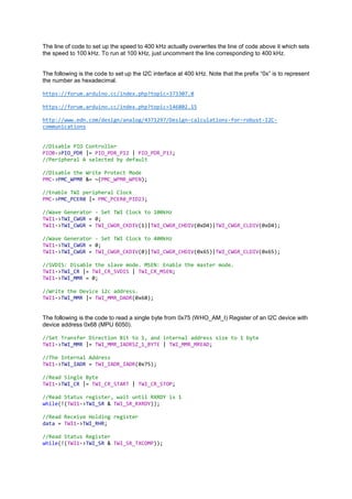
CREATE TIMER FUNCTIONS TO CREATE DELAYS OF SPECIFIC INTERVALS
In my project, I need a precision of at most 1 us. So I need a clock frequency of at least 1 MHz. There
are two sections in the datasheet through which we can create such timers. One is Section 13 RTT
(Real Time Timer) and the other is Section 36 TC (Timer Counter).
The RTT runs through the SWCLK (SLOW CLOCK) that has a clock frequency of 32.768 kHz, thus, is
not suitable for this project.
The TC can be made to run from 5 internal clock sources, that are MCK/2, MCK/8, MCK/32, MCK/128
and SWCLK (MCK refers to MAIN CLOCK). As sam3x8e is running at 84 MHz (MCK), the usable
frequencies are MCK/2, MCK/8 and MCK/32. I chose to use MCK/8 or 10.5 MHz for my clock frequency.
I found this blog which may be useful. The following is the code used for setting up the timer.
//Configure PMC
//Disable the Write Protect Mode
PMC->PMC_WPMR &= ~(PMC_WPMR_WPEN);
//Enable TC0 Peripheral Clock
PMC->PMC_PCER0 |= PMC_PCER0_PID27;
//Disable the Write Protect Mode
TC0->TC_WPMR &= ~(TC_WPMR_WPEN);
//Set Clock Source to MCK/8
TC0->TC_CHANNEL[0].TC_CMR |= TC_CMR_TCCLKS_TIMER_CLOCK2;
//Set Wave select to updown
TC0->TC_CHANNEL[0].TC_CMR |= TC_CMR_WAVE | TC_CMR_WAVSEL_UPDOWN;
//Enable Clock and trigger to start counter
TC0->TC_CHANNEL[0].TC_CCR |= TC_CCR_CLKEN | TC_CCR_SWTRG;
The following line of code is used to load the real time counter value onto a variable.
//Read current value from Counter Value Register
uint32_t counter = TC0->TC_CHANNEL[0].TC_CV;
ACTIVATE TWI INTERFACE TO COMMUNICATE WITH I2C SENSORS
This part is described in the datasheet under Section 33 Two-Wire Interface (TWI).There are two TWI
channels. I’m using the second channel (TWI1) which are pins SDA and SCL of Arduino Due and pins
B12 and B13 of sam3x8e (see the pin out).
First of all, I programmed the PIO controller to dedicate TWD and TWCK as peripheral lines. Then,
enabled the peripheral clock. And set the mode of operation to Master Mode. The steps of using TWI
in different modes are neatly displayed in a flowchart at the end of the TWI section.
5. The line of code to set up the speed to 400 kHz actually overwrites the line of code above it which sets
the speed to 100 kHz. To run at 100 kHz, just uncomment the line corresponding to 400 kHz.
The following is the code to set up the I2C interface at 400 kHz. Note that the prefix “0x” is to represent
the number as hexadecimal.
https://forum.arduino.cc/index.php?topic=373307.0
https://forum.arduino.cc/index.php?topic=146802.15
http://www.edn.com/design/analog/4371297/Design-calculations-for-robust-I2C-
communications
//Disable PIO Controller
PIOB->PIO_PDR |= PIO_PDR_P12 | PIO_PDR_P13;
//Peripheral A selected by default
//Disable the Write Protect Mode
PMC->PMC_WPMR &= ~(PMC_WPMR_WPEN);
//Enable TWI peripheral Clock
PMC->PMC_PCER0 |= PMC_PCER0_PID23;
//Wave Generator - Set TWI Clock to 100kHz
TWI1->TWI_CWGR = 0;
TWI1->TWI_CWGR = TWI_CWGR_CKDIV(1)|TWI_CWGR_CHDIV(0xD4)|TWI_CWGR_CLDIV(0xD4);
//Wave Generator - Set TWI Clock to 400kHz
TWI1->TWI_CWGR = 0;
TWI1->TWI_CWGR = TWI_CWGR_CKDIV(0)|TWI_CWGR_CHDIV(0x65)|TWI_CWGR_CLDIV(0x65);
//SVDIS: Disable the slave mode. MSEN: Enable the master mode.
TWI1->TWI_CR |= TWI_CR_SVDIS | TWI_CR_MSEN;
TWI1->TWI_MMR = 0;
//Write the Device i2c address.
TWI1->TWI_MMR |= TWI_MMR_DADR(0x68);
The following is the code to read a single byte from 0x75 (WHO_AM_I) Register of an I2C device with
device address 0x68 (MPU 6050).
//Set Transfer Direction Bit to 1, and internal address size to 1 byte
TWI1->TWI_MMR |= TWI_MMR_IADRSZ_1_BYTE | TWI_MMR_MREAD;
//The Internal Address
TWI1->TWI_IADR = TWI_IADR_IADR(0x75);
//Read Single Byte
TWI1->TWI_CR |= TWI_CR_START | TWI_CR_STOP;
//Read Status register, wait until RXRDY is 1
while(!(TWI1->TWI_SR & TWI_SR_RXRDY));
//Read Receive Holding register
data = TWI1->TWI_RHR;
//Read Status Register
while(!(TWI1->TWI_SR & TWI_SR_TXCOMP));
6. The following is the code to read multiple byte from 0x3B (ACC_X_HIGH_BYTE) Register of an I2C
device with device address 0x68 (MPU 6050).
//The 'device address' is used to access slave, set Transfer Direction Bit to 1
TWI1->TWI_MMR |= TWI_MMR_IADRSZ_1_BYTE | TWI_MMR_MREAD;
//The Internal Address
TWI1->TWI_IADR = TWI_IADR_IADR(0x3B);
//START
TWI1->TWI_CR |= TWI_CR_START;
int numofbytes = 14;
for(int i = 0; i<numofbytes-1; i++){
//Read Status register, wait until RXRDY is 1
while(!(TWI1->TWI_SR & TWI_SR_RXRDY));
//Read Receive Holding register
data = TWI1->TWI_RHR;
}
//STOP
TWI1->TWI_CR |= TWI_CR_STOP;
//Read Status register, wait until RXRDY is 1
while(!(TWI1->TWI_SR & TWI_SR_RXRDY));
//Read Receive Holding register
data = TWI1->TWI_RHR;
//Read Status Register
while(!(TWI1->TWI_SR & TWI_SR_TXCOMP));*/
The following is the code to write a single byte i.e. 0x00 from 0x00 (PWR_MGMT) Register of an I2C
device with device address 0x68 (MPU 6050).
//The 'device address' is used to access slave, set Transfer Direction Bit to 1
TWI1->TWI_MMR |= TWI_MMR_IADRSZ_1_BYTE;
TWI1->TWI_MMR &= ~(TWI_MMR_MREAD);
//The Internal Address
TWI1->TWI_IADR = TWI_IADR_IADR(0x00);
//Load data to be sent
TWI1->TWI_THR = 0x00;
//STOP
TWI1->TWI_CR |= TWI_CR_STOP;
//Read Status register, wait until TXRDY is 1
while(!(TWI1->TWI_SR & TWI_SR_TXRDY));
//Read Status Register
while(!(TWI1->TWI_SR & TWI_SR_TXCOMP));
7. Another thing that I realised, while writing this program was that the Arduino Due was reset after a fixed
interval. I remembered reading about Watchdog Timer while writing code for the TIMER section. So, I
we straight to Section 13 Watchdog Timer (WDT) of the datasheet. After disabling the watchdog timer
the processor doesn’t reset anymore. The following is the line of code to disable Watchdog Timer:
WDT->WDT_MR |= WDT_MR_WDDIS; //Disable the Watchdog Timer
ACTIVATE UART FUNCTION TO COMMUNICATE WITH THE PC
This part is described in the datasheet under Section 34 Universal Asynchronous Receiver Transceiver
(UART). Pin RX0 and TX0 of Arduino Due (pins PA8 and PA9 of sam3x8e) are the UART pins. The
following code initializes the UART communication at 57600 bps. I also posted the code in this forum.
//Enable UART Peripheral Clock
PMC->PMC_PCER0 |= PMC_PCER0_PID8;
//Initialize RX and TX pins
PIOA->PIO_PDR |= PIO_PDR_P8|PIO_PDR_P9;//Peripheral A(RX & TX) are enabled by default
//Disable PDC Channel
UART->UART_PTCR = UART_PTCR_RXTDIS | UART_PTCR_TXTDIS;
//Reset and disable receiver and transmitter
UART->UART_CR = UART_CR_RSTRX | UART_CR_RSTTX | UART_CR_RXDIS | UART_CR_TXDIS;
//Configure Mode
UART->UART_MR |= UART_MR_PAR_NO | UART_MR_CHMODE_NORMAL;//No Parity and normal CH mode
//Configure Rate Generator
UART->UART_BRGR |= UART_BRGR_CD(91); //Baud rate set to 57600 bps
// Configure interrupts
UART->UART_IDR = 0xFFFFFFFF;
UART->UART_IER = UART_IER_RXRDY | UART_IER_OVRE | UART_IER_FRAME;
// Enable receiver and transmitter
UART->UART_CR = UART_CR_RXEN | UART_CR_TXEN;
To transmit data, write data to the THR register and wait until the TXRDY bit is set in the UART Status
Register. The following example sends A via UART.
UART->UART_THR = ‘A’; //Write to UART_THR to send ‘A’
while(!(UART->UART_SR & UART_SR_TXRDY)); //Wait till data is sent and THR is empty
ACTIVATE INTERRUPT SERVICE TO ACT WHENEVER PIN STATE TOGGLES
Using interrupts on GPIO pins is quite straight forward. It is described in Section 10 ARM Cortex M3
Processor under subsection: Nested Vectored Interrupt Controller (NVIC). First NVIC needs to be set
up to enable Handler functions. The code to be run in the interrupt is written under the Handler functions.
Here is a link that I referred. Below is the code to enable Edge Detection Interrupt on pin 12 of Arduino
Due. That is pin D8 of sam3x8e (see the pin out).
//Enable Interrupts
PIOD->PIO_IER |= PIO_IER_P8;