This document contains instructions for a midterm examination in a data communications course. It provides details such as the date, time, duration, and location of the exam. It instructs students on exam policies including remaining in the exam room, turning off devices, and filling out personal details on the answer sheet. The document also provides relevant formulas and assumptions to be used in answering exam questions.

![Part A – Multiple Choice Questions [22 marks]
Select the most accurate answer (only select one answer). Each correct answer is worth 2 marks.
Incorrect answer is 0 marks. No answer is 0 marks.
1. Which technique is used for transmitting analog data as digital signals?
a) Frequency Modulation
b) Pulse Code Modulation
c) Quadrature Amplitude Modulation
d) Binary Frequency Shift Keying
e) Manchester Encoding
f) None of the above
2. Which of the following is an example of a network layer address?
a) 00:17:31:7e:50:7d
b) its323@ict.siit.tu.ac.th
c) www.siit.tu.ac.th
d) 72.103.16.5
e) Port 22
f) None of the above
3. What is the absolute bandwidth of the signal:
st =15sin2000t5sin 6000t3sin 10000t 2
1
7
sin14000t
a) 1000 Hz
b) 2000 Hz
c) 3000 Hz
d) 6000 Hz
e) 10000 Hz
f) 12000 Hz
g) 14000 Hz
h) 28000 Hz
4. Which technique can be described as “vary the frequency of the output carrier signal as the
amplitude of the input data changes”:
a) Frequency Modulation
b) Frequency Shift Keying
c) Quadrature Amplitude Modulation
d) Bipolar AMI Encoding
e) Phase Modulation
f) Delta Modulation
5. Which of the following is incorrect?
a) Optical fibre provides higher data rates than electrical cabling technologies
b) With coaxial cable signals can be transmitted over a large distance than with twister pair.
c) Unshielded twister pair is easier to install than shielded twisted pair
d) Electrical cable technologies are designed to minimise the effects of interference from
other sources on the transmitted signal
e) The most common technology used in home telephone lines and in-building LANs
is coaxial cable
f) Optical fibre can be used over larger distances the twisted pair.
6. Quadrature PSK uses the phases: 45°, 135°, 225°, 315°. If the duration of each signal
2](https://image.slidesharecdn.com/its323y09s1e01-midterm-exam-answers-191025070105/85/Its323-y09s1e01-midterm-exam-answers-2-320.jpg)
![Part B – General Questions [78 marks]
Question 1 [12 marks]
a) The following digital signal was encoded using NRZ-Invert. What is the digital data? (Fill in
the boxes). [3 marks]
Answer
4](https://image.slidesharecdn.com/its323y09s1e01-midterm-exam-answers-191025070105/85/Its323-y09s1e01-midterm-exam-answers-4-320.jpg)
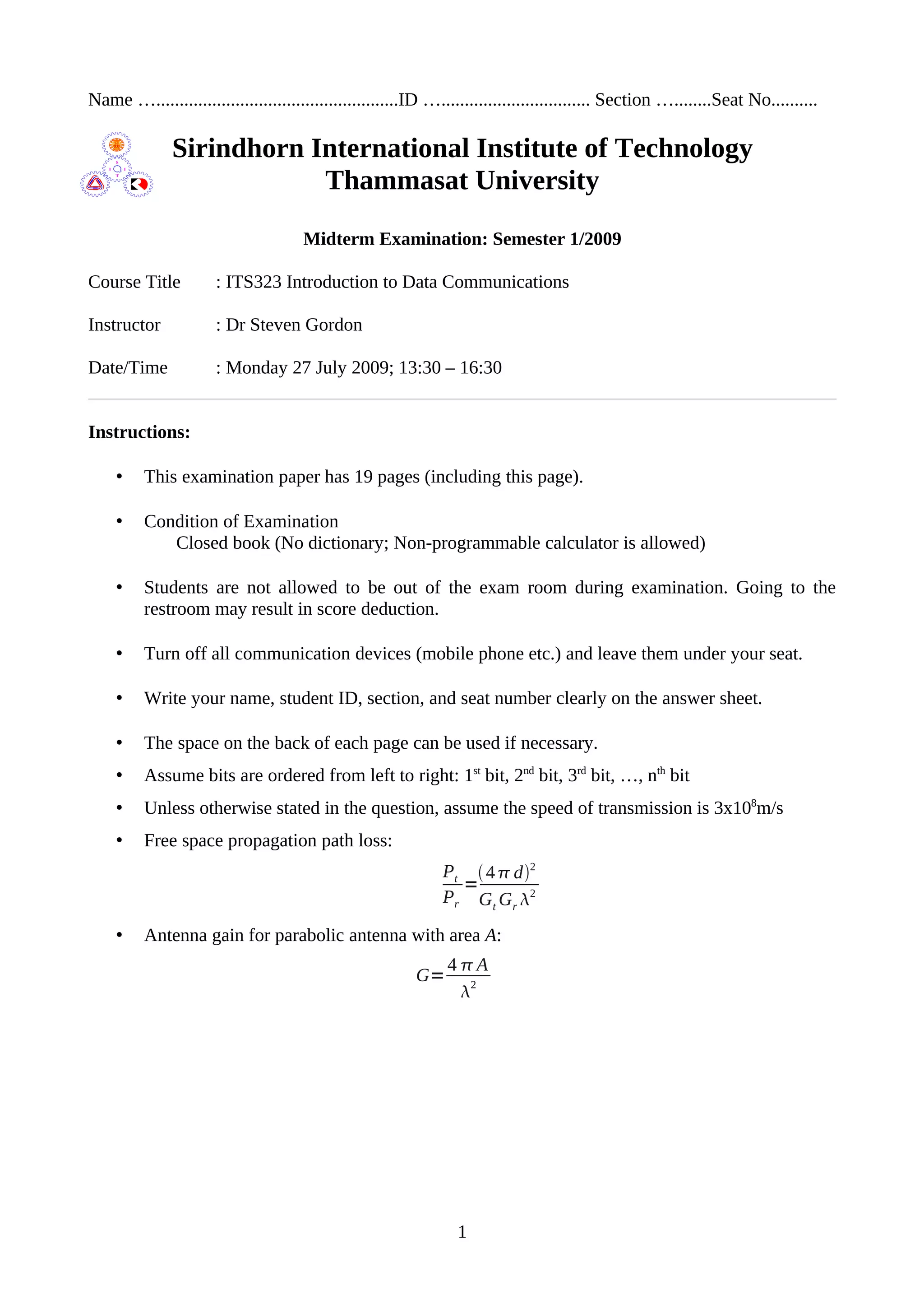
![b) The Pseudoternary digital encoding scheme alternates between positive and negative voltage
levels between successive bit 0's, and uses zero voltage for bit 1. Write the received bits in
the boxes for the following received digital signal. [3 marks]
Answer
The following data is to be sent using a combination of FSK and ASK. There are 2 possible
frequencies and 4 possible amplitudes.
010101001001010110110111
c) Select and describe a mapping of bits to signals (sinusoids) that uses all possible
combinations of frequencies and amplitudes. [3 marks]
Answer
A possible mapping:
000 A=1 f=1
001 A=2 f=1
010 A=3 f=1
011 A=4 f=1
100 A=1 f=2
5](https://image.slidesharecdn.com/its323y09s1e01-midterm-exam-answers-191025070105/85/Its323-y09s1e01-midterm-exam-answers-5-320.jpg)
![101 A=2 f=2
110 A=3 f=2
111 A=4 f=2
d) Using the mapping you selected in part (c), draw the analog signal to be transmitted. [3
marks]
Answer
6](https://image.slidesharecdn.com/its323y09s1e01-midterm-exam-answers-191025070105/85/Its323-y09s1e01-midterm-exam-answers-6-320.jpg)
![Question 2 [11 marks]
Consider a point-to-point wireless communications system using two parabolic antennas:
• Transmit antenna diameter: 1 metre
• Receive antenna gain: 20dBi
• Signal frequency: 3GHz
• Distance between transmitter and receiver: 10km
• Receive power threshold: -80dBm
a) Assuming free space path loss, what is the minimum transmit power required? [6 marks]
Answer
Wavelength: =
3×10⁸
3×10
9
=0.1m
Gain of transmit antenna: Gt=
40.52
0.1
2
=986.9604...
Absolute gain of receive antenna: Gr=1020/10
=100
Receive power: Pr=10−80/10
=10−8
mW=10−11
W
Transmit power:
Pt=
Pr4d2
Gt Gr
2
=
10
−11
16
2
10000
2
986.9604×100×0.01
=1.6×10
−4
W=160uW
The transmit power required is 160uW.
In the free space path loss model, the absolute path loss (L) between the two antenna's can be
written as:
L=
4d2
2
However, the free space path loss model does not consider obstructions or other environmental
factors. Assume you have measured the real path loss between the two antennas to be LdB =
130dB
b) Using the measured path loss (instead of free space path loss), what is the minimum transmit
power required? [5 marks]
Answer
Absolute loss: L=10130 /10
=1013
7](https://image.slidesharecdn.com/its323y09s1e01-midterm-exam-answers-191025070105/85/Its323-y09s1e01-midterm-exam-answers-7-320.jpg)
![Question 3 [9 marks]
A standard encoding format for digital telephony is Pulse Code Modulation.
a) Assuming the human voice has a spectrum of frequencies ranging from 200Hz to 4000Hz,
what sampling rate should be used to retain all necessary information in the digital data? [1
mark]
Answer
Using the Nyquist-Shannon sampling theorem the sampling rate should be twice the highest
frequency component.
Sampling rate = 2 x 4000 = 8000 samples per second.
Assume that the number of code levels used for PCM in a telephone system is 16. The following
sequence of bits are the PCM encoded digital data received by a destination telephone (assume no
errors).
0101001100110010010001111010101010111100
b) On the figure below draw the output analog audio signal at the destination telephone. The
horizontal dotted lines should be used as the levels, and the vertical dashed lines as the
sample points. [3 marks]
Answer
9](https://image.slidesharecdn.com/its323y09s1e01-midterm-exam-answers-191025070105/85/Its323-y09s1e01-midterm-exam-answers-9-320.jpg)
![In practice, the number of code levels used in telephone systems is normally 128 (instead of 16).
Assume this is the case in the following parts.
c) If SIIT Bangkadi has a 1Mb/s link to SIIT Rangsit, how many PCM encoded voice calls can
be sent from Bangkadi to Rangsit at the same time (ignore other overheads such as
headers)? [3 marks]
Answer
8000 samples per second with each sample 7 bits gives a data rate required per voice call of
56kb/s. Therefore 17 voice calls can be transmitted at a time over a 1Mb/s link.
d) Some applications that transmit voice over the Internet (such as Skype, MSN) may use
lower sampling rates and less code levels than above. Referring to part (c), that is the
number of voice calls, explain an advantage and disadvantage of changing these values for
voice applications [2 marks]
Advantage of lower sampling rates, less code levels
Answer
Leads to lower data rate required, meaning more voice calls can be sent over the same
link/network at the same time.
Disadvantage of lower sampling rates, less code levels
Answer
Output generated at destination is lower quality, that is, low quality audio reproduction at the
receiver.
10](https://image.slidesharecdn.com/its323y09s1e01-midterm-exam-answers-191025070105/85/Its323-y09s1e01-midterm-exam-answers-10-320.jpg)
![Question 4 [16 marks]
Table 1 shows the list of codewords for a Hamming-distance based Forward Error Correction
(FEC) scheme.
Data Codeword
000 011011
001 100110
010 100111
011 010000
100 111100
101 001010
110 100101
111 001011
Table 1: Hamming-based FEC
a) For the following cases, explain the steps taken by the receiver (showing any calculations
where necessary), and summarise the outcome by answering the 4 questions. [9 marks]
i. The data 010 is to be sent from transmitter to receiver. The 1st
bit transmitted is in error
(that is, the 1st
bit transmitted is different from the 1st
bit received).
Steps taken by receiver:
Codeword received by receiver: ___ ___ ___ ___ ___ ___
Error detected by receiver? YES NO
Data received: ___ ___ ___ (if applicable)
Is the correct data received? YES NO
Answer
Data 010 maps to codeword 100111. The codeword is transmitted, however because of the
single bit error the receive codeword is 000111.
The receiver detects an error, and compares the received codeword to the valid codewords. The
valid codeword with unique minimum Hamming distance to 000111 is 100111 (distance = 1).
Therefore the receiver assumes the data received is 010. This is the correct assumption.
ii. The data 100 is to be sent from transmitter to receiver. The 1st
and 2nd
bits transmitted are
in error.
Steps taken by receiver:
Codeword received by receiver: ___ ___ ___ ___ ___ ___
11](https://image.slidesharecdn.com/its323y09s1e01-midterm-exam-answers-191025070105/85/Its323-y09s1e01-midterm-exam-answers-11-320.jpg)
![Error detected by receiver? YES NO
Data received: ___ ___ ___ (if applicable)
Is the correct data received? YES NO
Answer
Data 100 maps to codeword 111100. The codeword is transmitted, however because of the bit
errors the receive codeword is 001100.
The receiver detects an error (the received codeword is invalid), and compares the received
codeword to the valid codewords. There is no valid codeword with minimum Hamming
distance (both 111100 and 001010 have distance of 2). Therefore error correction is not
attempted, and the correct data is not received.
iii. The data 001 is to be sent from transmitter to receiver. The last bit transmitted is in error.
Steps taken by receiver:
Codeword received by receiver: ___ ___ ___ ___ ___ ___
Error detected by receiver? YES NO
Data received: ___ ___ ___ (if applicable)
Is the correct data received? YES NO
Answer
Data 001 maps to codeword 100110. The codeword is transmitted, however because of the bit
error the receive codeword is 100111.
The receiver has received a valid codeword (and hence no error detected). It assumes the
received data is 010, which is incorrect.
b) Assuming you must use a FEC with 3 bits of data and 6-bit codeword, explain how the
scheme in Table 1 could be changed to reduce the possibility of single-bit errors being
undetected. [3 marks]
Answer
Choose a different set of code words. For example, codewords for data 001 and 010 differ only
by a single bit. Therefore if data 001 is transmitted, a single-bit error will be undetected if the
received codeword matches that for 010. The codewords should have large Hamming distance
between each other.
c) If using a link with data rate of 12Mb/s, what is the maximum possible throughput using the
encoding scheme in Table 1? [2 marks]
Answer
To send 3 bits of data, 6 bits actually have to be transmitted, representing 50% efficiency.
12](https://image.slidesharecdn.com/its323y09s1e01-midterm-exam-answers-191025070105/85/Its323-y09s1e01-midterm-exam-answers-12-320.jpg)
![Throughput is 6Mb/s.
d) Explain one advantage and one disadvantage of using an 8-bit codeword (instead of 6-bit
codeword as in Table 1). [2 marks]
Advantage
Answer
Increases the chance to detect and correct errors
Disadvantage
Answer
Decreases the throughput
13](https://image.slidesharecdn.com/its323y09s1e01-midterm-exam-answers-191025070105/85/Its323-y09s1e01-midterm-exam-answers-13-320.jpg)
![Question 5 [14 marks]
Consider a network with two links: A --- B --- C.
First consider the link from A to B with the following characteristics.
• DATA frame consists of 100 bits of header plus 9900 bits of data (total size 10,000 bits)
• ACK frame consists only of 100 bits of header
• Link data rate is 100Mb/s
• Link distance is 120km
• Link signal speed is 3x10⁸
m/s
The Sliding Window flow control protocol is used on this link. The receiver (B) sends an ACK
frame immediately after receiving a DATA frame (there is no processing delay). A 3-bit
sequence number is used within the header of the DATA frame (and ACK frame).
a) What is the maximum number of DATA frames node A can send before having to wait for
an ACK? [1 mark]
Answer
With a 3-bit sequence number the maximum window size is 23
-1. Therefore 7 frames may be
sent before having to wait for an ACK.
b) Assuming node A always has data ready to send, and it starts transmission of its 1st
DATA
frame at time 0s, at what time can node A start transmitting the 2nd
DATA frame? [2 marks]
Answer
Immediately after the 1st
DATA frame has been transmitted. The transmission time of a DATA
frame is:
TDATA=
9900100
100×10
6
=100us
Therefore, 2nd
DATA frame can be sent at time 100us.
c) At what time can node A start transmitting the 8th
DATA frame? [4 marks]
Answer
As the maximum window size is 7, the transmitter must wait until at least the 1st
DATA frame
is ACKed before sending the 8th
DATA frame. See the diagram:
14](https://image.slidesharecdn.com/its323y09s1e01-midterm-exam-answers-191025070105/85/Its323-y09s1e01-midterm-exam-answers-14-320.jpg)
![The ACK transmission time and Propagation delay are:
T ACK=
100
100×10
6
=1us
PAB=
120×103
3×10
8
=4×10
−4
=400us
The time at which the ACK for the 1st
DATA frame is received is: 901us
Note that the first 7 DATA frames are transmitted within 700us. Therefore the transmitter must
wait until time 901us before sending the 8th
frame.
d) What is the maximum throughput that can be achieved across the link from A to B? [3
marks]
Answer
7 DATA frames sent within 901us, gives a throughput of:
Throughput=
7×9900
901×10
−6
=76.91Mb/s
Now consider the link from B to C with the following characteristics:
15](https://image.slidesharecdn.com/its323y09s1e01-midterm-exam-answers-191025070105/85/Its323-y09s1e01-midterm-exam-answers-15-320.jpg)
![• DATA frame consists of 100 bits of header plus 9900 bits of data (total size 10,000 bits)
• ACK frame consists only of 100 bits of header
• Link distance is 1200m
• Link signal speed is 3x10⁸
m/s
The Stop and Wait flow control protocol is used in this link.
e) What is the minimum data rate necessary for Link B to C such that the throughput from A to
C is the same as calculated in part (d)? [4 marks]
Answer
At B, 7 DATA frames arrive every 901us. Therefore to achieve the same throughput from B to
C, 7 DATA frames must be delivered to C every 901us. Considering Stop and Wait is used
from B to C:
PBC=
1200
3×10
8
=4us
Time for sending 7 DATA frames:
7×
10000
Rate
2×PBC
100
Rate
=901us
Rate=
10100
901
7
−8
=83.66Mb/s
The data rate necessary is 83.66Mb/s.
16](https://image.slidesharecdn.com/its323y09s1e01-midterm-exam-answers-191025070105/85/Its323-y09s1e01-midterm-exam-answers-16-320.jpg)
![Question 6 [7 marks]
High Definition TV consists of a 1920 x 1080 pixel image, refreshed at a rate of 30 images per
second. 24-bit colour is used – that is, each pixel is a 24-bit colour value.
a) What is the data rate required to transmit an uncompressed HDTV movie in real-time? [3
marks]
Answer
Data rate: 1920 x 1080 x 30 x 24 bits per second = 1492 Mb/s
b) Compression is often used to reduce the data rate necessary for sending video. Under some
circumstances, HDTV can be compressed to 5% of its original size. What is the data rate
required to transmit a compressed HDTV movie in real-time? [1 mark]
Answer
5% of 1492 = 75Mb/s
c) In a noise-free channel, what is the minimum number of signal levels necessary to transmit
the compressed HDTV within 6MHz of bandwidth? (Note the number of signal levels must
be a power of 2) [3 marks]
Answer
Using Nyquists theorem:
75Mb/s = 2 * 6MHz log (M)
M must be at least 128 (64 would be too small)
17](https://image.slidesharecdn.com/its323y09s1e01-midterm-exam-answers-191025070105/85/Its323-y09s1e01-midterm-exam-answers-17-320.jpg)
![Question 7 [9 marks]
Table 2 shows a set of frames received by the Data Link layer of a computer (including the time
when it is received). Each frame contains a header plus data. The amount of data in each frame is
shown in the Data column. The Data Link layer header contains five fields:
1. A 16-bit timestamp, which indicates the time when the frame was sent
2. Address of the source, in the format of a 48-bit IEEE address
3. Address of the destination, in the format of a 48-bit IEEE address
4. A 32-bit sequence number
5. A 2 byte field to indicate the type of protocol used.
Time received [ms] Sequence number Timestamp [ms] Data [Bytes]
7 0 0 100
11 1 3 120
14 2 6 150
16 3 9 125
22 4 12 100
23 5 15 125
Table 2: Frames Received
Answer the following questions considering only the frames in the table.
a) What is the average delay from source to destination? [2 marks]
Answer
Delay of packets are: 7, 8, 8, 7, 10, 8. Average delay is 48/6 = 8ms
b) What is the jitter between source and destination? [2 marks]
Answer
The difference between delays is: 1, 0, 1, 3, 2. Jitter is 7/5 = 1.4ms
c) What is the throughput for the received data? [2 marks]
Answer
There is 720 Bytes of data received over a period of 16ms. Throughput is 45000 Bytes/second
or 360kb/s.
d) Consider the source sending the frames. Assume the Physical layer at the source adds an
additional 80 bits to each frame. What is the average rate at which bits are sent by the source
Physical layer? [3 marks]
Answer
18](https://image.slidesharecdn.com/its323y09s1e01-midterm-exam-answers-191025070105/85/Its323-y09s1e01-midterm-exam-answers-18-320.jpg)