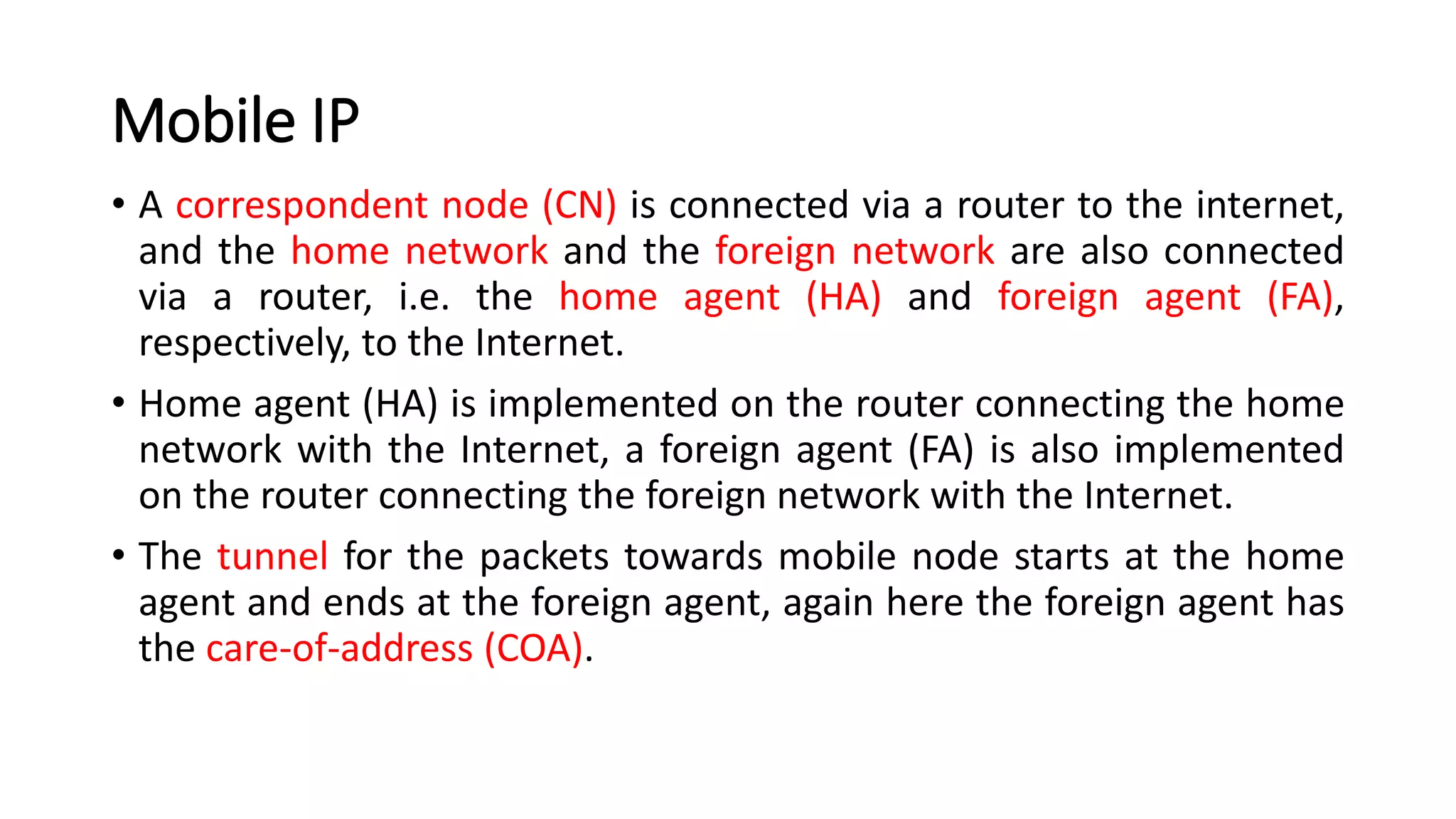
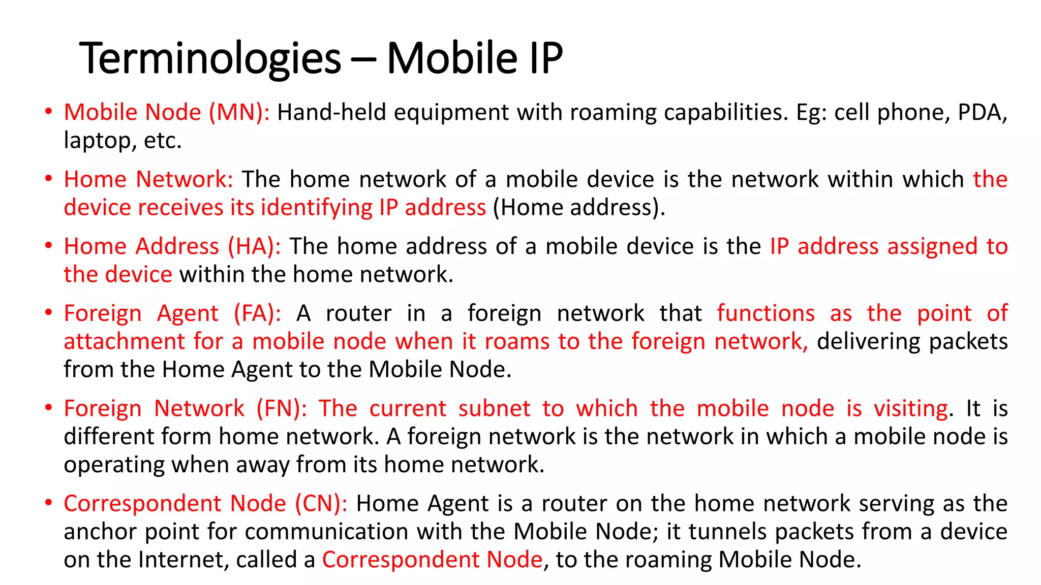
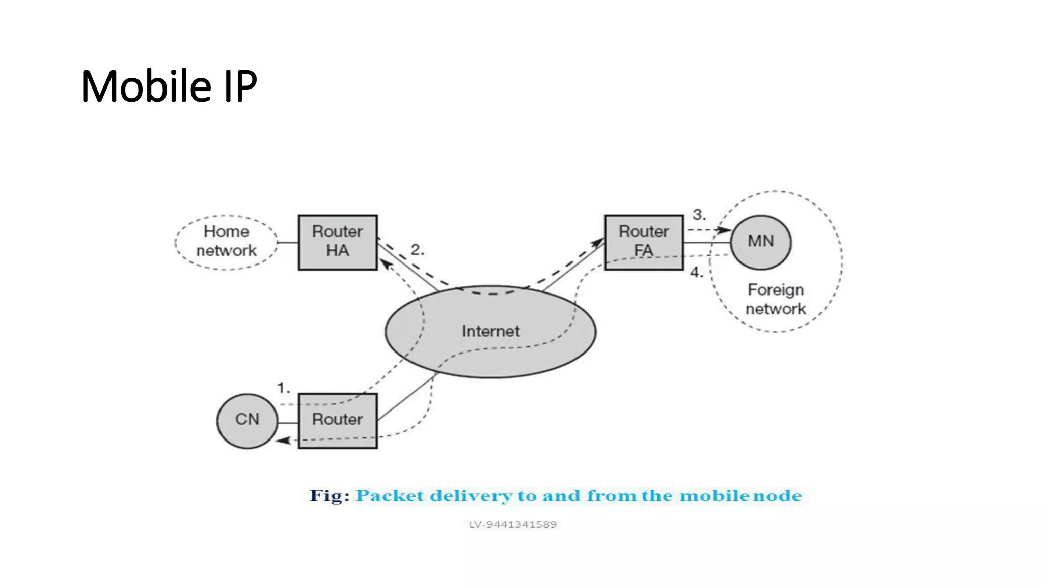
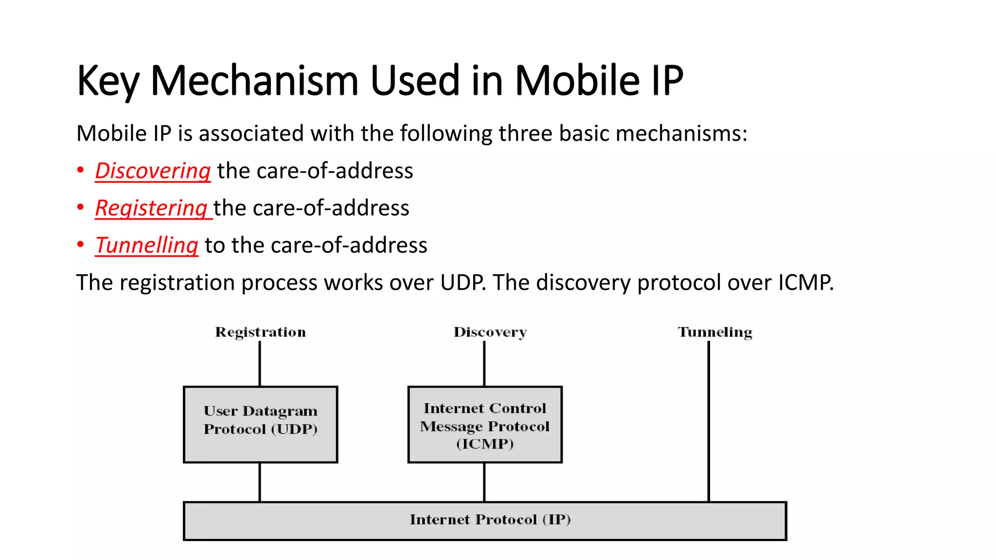
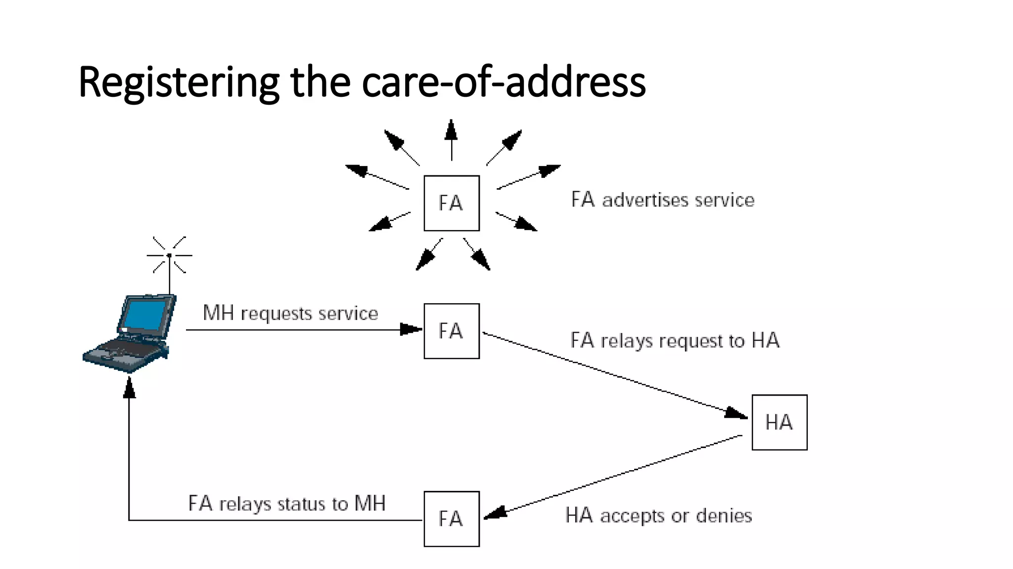
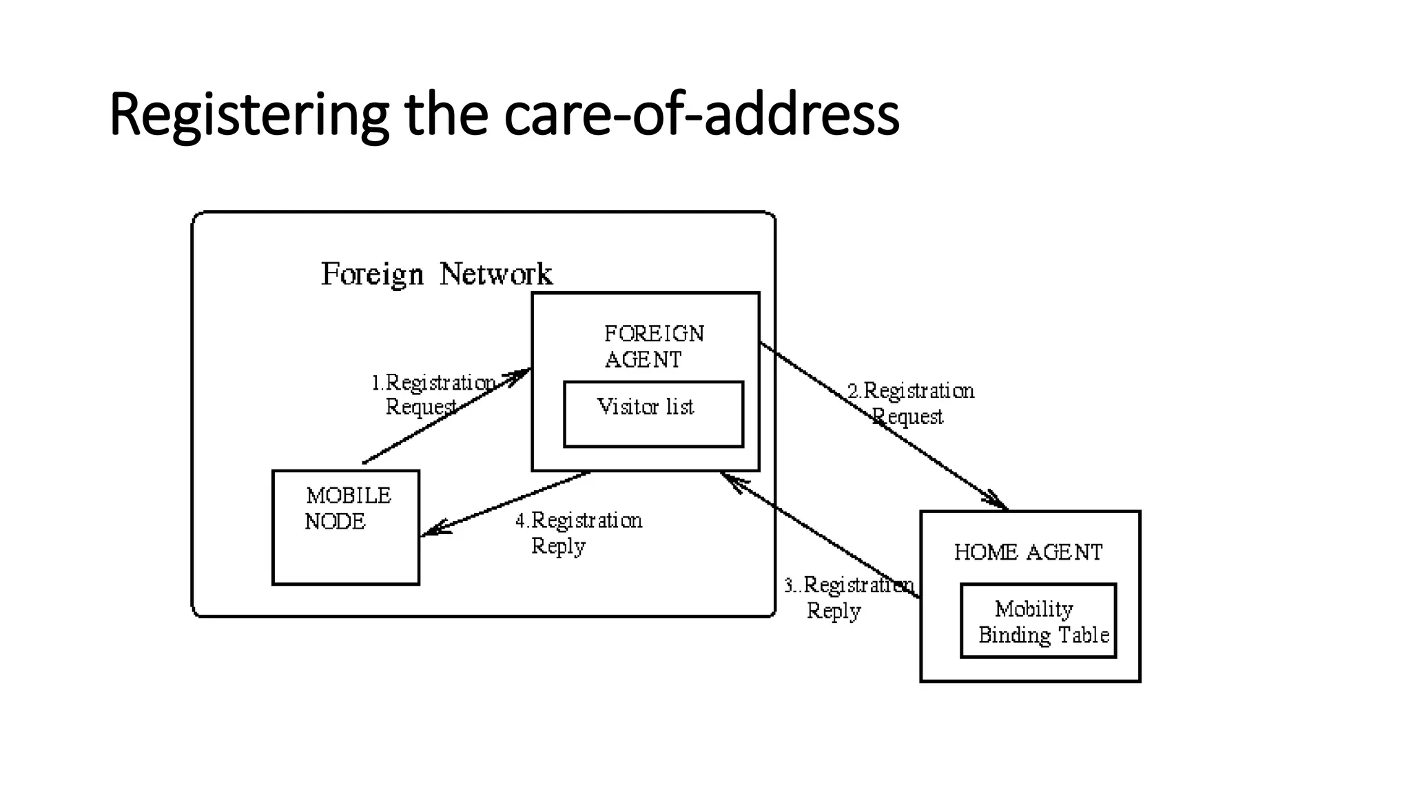
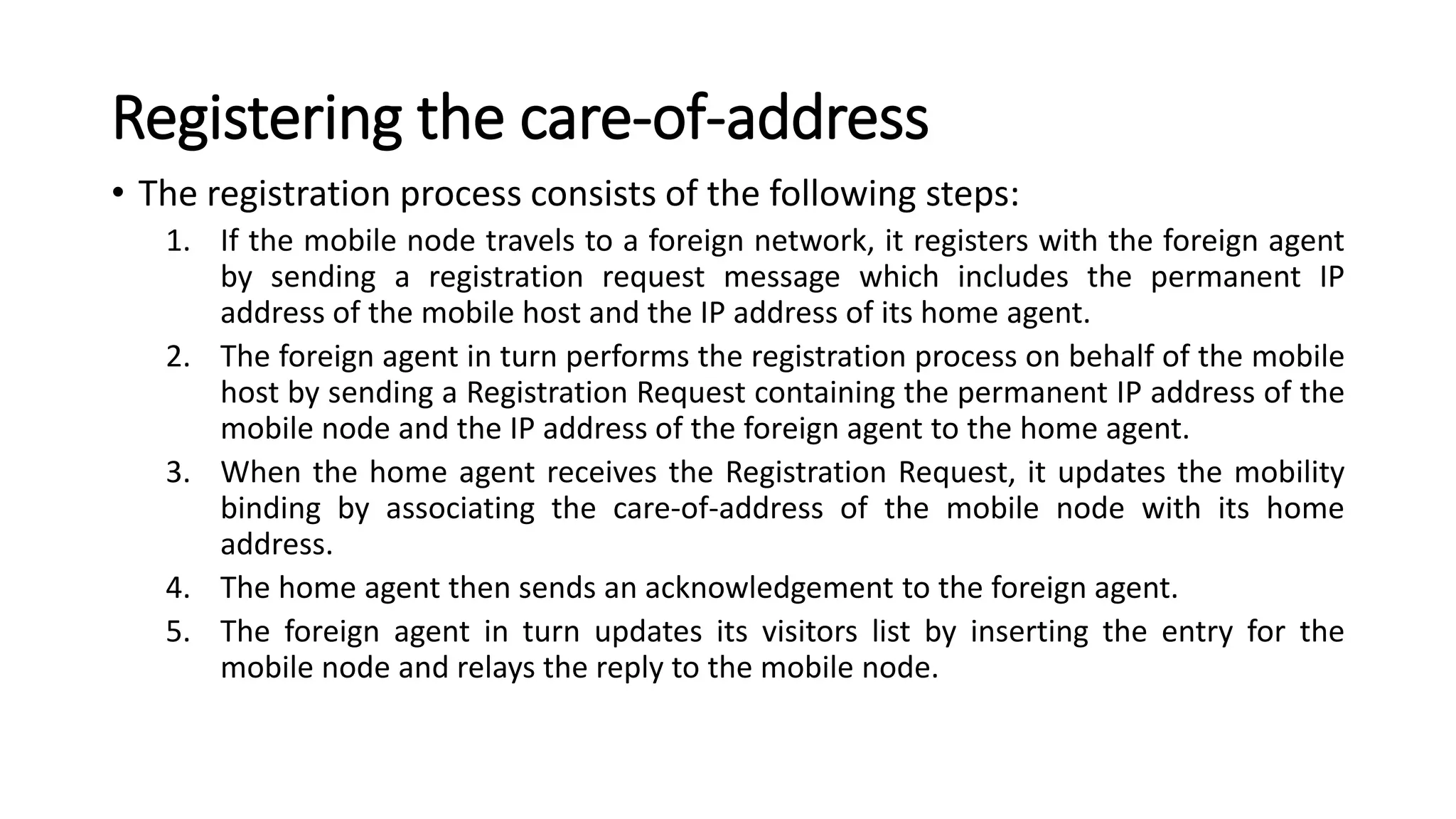
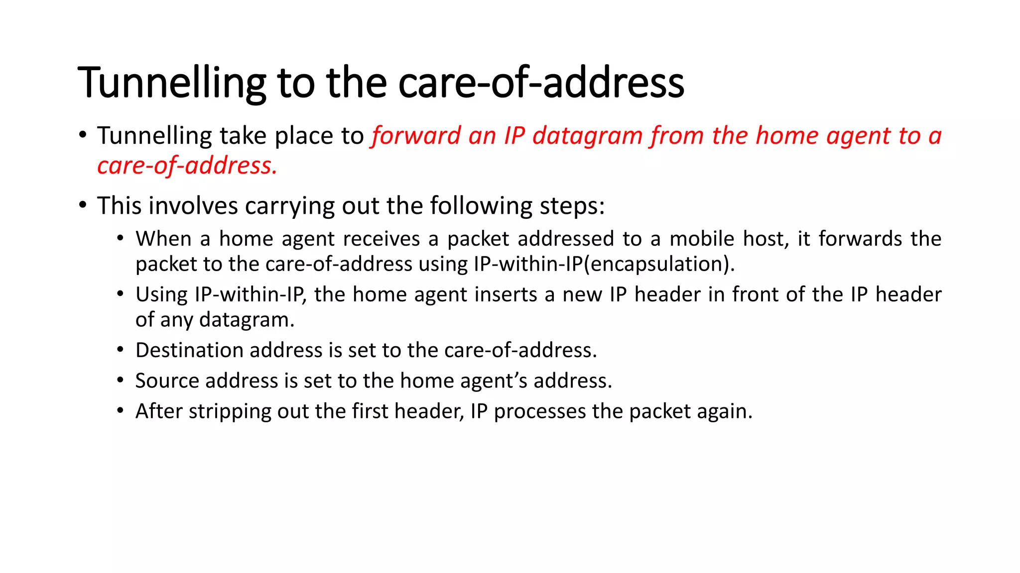
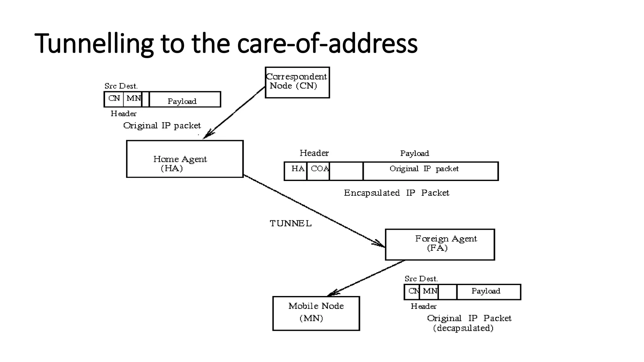
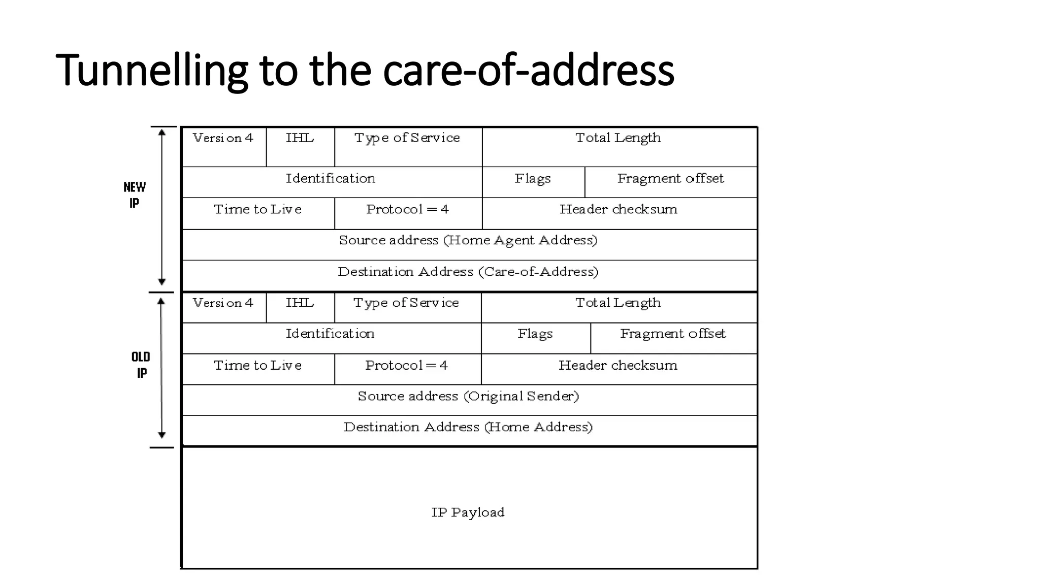
IT6601 – MOBILE COMPUTING
UNIT – II
MOBILE INTERNET PROTOCOL &
TRANSPORT LAYER
KAVIYA P
Assistant Professor
Kamaraj College of Engineering & Technology
MOBILE IP
Mobile IP - Definition
• Mobile Internet Protocol (Mobile IP) was proposed by the Internet
Engineering Task Force (IETF).
• The mobile IP allows mobile computers to stay connected to the
Internet regardless of their location and without changing their IP
address.
• Mobile IP is a standard protocol that extends the Internet Protocol by
making mobility transparent to applications and to higher level
protocols like TCP.
• Every mobile user likes to have a continuous network connectivity
irrespective of its physical location.
Mobile IP
Mobile IP
• A correspondent node (CN) is connected via a router to the internet,
and the home network and the foreign network are also connected
via a router, i.e. the home agent (HA) and foreign agent (FA),
respectively, to the Internet.
• Home agent (HA) is implemented on the router connecting the home
network with the Internet, a foreign agent (FA) is also implemented
on the router connecting the foreign network with the Internet.
• The tunnel for the packets towards mobile node starts at the home
agent and ends at the foreign agent, again here the foreign agent has
the care-of-address (COA).
Terminologies – Mobile IP
• Mobile Node (MN): Hand-held equipment with roaming capabilities. Eg: cell phone, PDA,
laptop, etc.
• Home Network: The home network of a mobile device is the network within which the
device receives its identifying IP address (Home address).
• Home Address (HA): The home address of a mobile device is the IP address assigned to
the device within the home network.
• Foreign Agent (FA): A router in a foreign network that functions as the point of
attachment for a mobile node when it roams to the foreign network, delivering packets
from the Home Agent to the Mobile Node.
• Foreign Network (FN): The current subnet to which the mobile node is visiting. It is
different form home network. A foreign network is the network in which a mobile node is
operating when away from its home network.
• Correspondent Node (CN): Home Agent is a router on the home network serving as the
anchor point for communication with the Mobile Node; it tunnels packets from a device
on the Internet, called a Correspondent Node, to the roaming Mobile Node.
• Care-of-Address (COA): It is the address that is used to identify the present
location of a foreign agent.
• The packets sent to the MN are delivered to COA.
• The COA can be any of the following two types:
• Foreign agent COA: The COA is an IP address of foreign agent (FA).
• CO-located COA: When the mobile node (MN) acquires a temporary IP address, that
address acts as the COA. (acquired using services like DHCP)
• Home Agent (HA): It is located in home network and it provides several services
for the MN. HA maintains a location registry. The location registry keeps track of
the node locations using the current care-of-address of the MN.
• Agent Discovery: During call establishment it is necessary for a mobile node to
determine its foreign agent. This task is referred to as agent discovery.
• Agent advertisement
• Agent Solicitation
Tunnelling and Encapsulation
• Tunnelling establishes a virtual pipe for the packets available between a tunnel
entry and an endpoint.
• Tunnelling is the process of sending a packet via a tunnel and it is achieved by a
mechanism called encapsulation.
• Encapsulation refers to arranging a packet header and data in the data part of the
new packet.
• On the other hand, disassembling the data part of an encapsulated packet is
called decapsulation.
• Whenever a packet is sent from a higher protocol layer to a lower protocol layer,
the operations of encapsulation and decapsulation usually take place.
MOBILE IP – PACKET DELIVERY
Mobile IP
Packet Delivery
Corresponding node (CN) wants to send an IP packet to a Mobile node (MN)
1. CN sends the packet to the IP address of the mobile node.
• The IP address of the MN is the destination address, whereas the address of CN is the source
address.
• The packet is passed to the Internet that does not have any information about the MN’s
current location.
• So the internet routes the packet to the router of the MN’s home network.
• The home agent (HA) examines the packet to determine whether the MN is present in its
current home network or not.
• In case that MN is not present, then the packet is encapsulated by a new header that is
placed in front of the existing IP header.
Packet Delivery
Corresponding node (CN) wants to send an IP packet to a Mobile node (MN)
2. The encapsulated packet is tunneled to the COA, which act as the new
destination address and the HA acts as the source address of the packet.
3. The encapsulated packet is routed to the foreign agent which performs
decapsulation to remove the additional header and forwards the decapsulated
packets to the MN, which is the actual destination, as specified by the source
node (CN).
4. The MN after receiving the packet from CN, forwards a reply packet to the CN
by specifying its own IP address along with the address of the CN.
• The MN’s IP address acts as the source address and the CN’s IP address acts as the
destination address.
• The packet is routed to the FA. After receiving the packet, FA forwards the packet to CN.
Overview of Mobile IP
• The steps used in the operation of mobile IP are the following:
Step 1:
The remote client sends a datagram to the MN using its home address.
It reaches the home agent (say Delhi) as usual.
Step 2:
The home agent encapsulates that datagram in a new packet and sends
it to the foreign agent (say Singapore)
MOBILE IP FEATURES
Desirable Features of Mobile IP
• Transparency: A mobile end-system should continue to keep its IP address and
there should not be any disruption of communication after any movement. The IP
address is to be managed transparently and there should not any effect of
mobility on any on-going communication.
• Compatibility: Mobile IP should be compatible with the existing Internet
protocols.
• Security: Mobile IP should provide users with secure communications over the
Internet.
• Efficiency and Scalability: In the event of world wide support, there can be a large
number of mobile systems in the whole Internet. This should neither result in
large number of messages nor should it incur too much computational overhead.
It should also be scalable to support billions of moving hosts world wide.
KEY MECHANISM IN MOBILE IP
Key Mechanism Used in Mobile IP
Mobile IP is associated with the following three basic mechanisms:
• Discovering the care-of-address
• Registering the care-of-address
• Tunnelling to the care-of-address
The registration process works over UDP. The discovery protocol over ICMP.
Discovering the care-of-address
• Each mobile node uses a discovery protocol to identify the respective
home and foreign agents.
• The discovery of the care-of-address consists of the following
important steps:
• Mobile agents advertise their presence by periodically broadcasting the agent
advertisement messages.
• The mobile node receiving the agent advertisement message observes
whether the message is from its own home agent and determines whether it
is on the home network or on a foreign network.
• If a mobile node does not wish to wait for the periodic advertisement, it can
send out agent solicitation messages that will be responded to the mobility
agent.
Discovering the care-of-address
The process of agent advertisement, involves the following activities:
• Foreign agents send messages to advertise the available care-of-
addresses
• Home agents send advertisements to make themselves known.
• Mobile hosts can issue agent solicitation to actively seek information.
• If a mobile host has not heard from the foreign agent to which its
current care-of-address belongs, it takes up another care-of-address.
Registering the care-of-address
• If a mobile node discovers that it is on the home network. It operates
normally without using any mobility services.
• While a node has moved to a different network, if the mobile node obtains
a care-of-address from a foreign agent, then this address should be
registered with the home agent.
• The mobile node sends a request for registration to its home agent along
with the care-of-address information.
• Whenever the home agent receives the registration request information,
the routing table is updated and it sends back the registration reply to the
mobile node.
• The mobile node makes use of the registration procedure to intimate the
care-of-address to a home agent.
Registering the care-of-address
• The registration process consists of the following steps:
1. If the mobile node travels to a foreign network, it registers with the foreign agent
by sending a registration request message which includes the permanent IP
address of the mobile host and the IP address of its home agent.
2. The foreign agent in turn performs the registration process on behalf of the mobile
host by sending a Registration Request containing the permanent IP address of the
mobile node and the IP address of the foreign agent to the home agent.
3. When the home agent receives the Registration Request, it updates the mobility
binding by associating the care-of-address of the mobile node with its home
address.
4. The home agent then sends an acknowledgement to the foreign agent.
5. The foreign agent in turn updates its visitors list by inserting the entry for the
mobile node and relays the reply to the mobile node.
Tunnelling to the care-of-address
• Tunnelling take place to forward an IP datagram from the home agent to a
care-of-address.
• This involves carrying out the following steps:
• When a home agent receives a packet addressed to a mobile host, it forwards the
packet to the care-of-address using IP-within-IP(encapsulation).
• Using IP-within-IP, the home agent inserts a new IP header in front of the IP header
of any datagram.
• Destination address is set to the care-of-address.
• Source address is set to the home agent’s address.
• After stripping out the first header, IP processes the packet again.
Tunnelling to the care-of-address
ROUTE OPTIMIZATION
Route Optimization
• In the mobile IP protocol, all the data packets to the mobile node go
through the home agent.
• Because of this there will be heavy traffic between HA and CN in the
network, causing latency to increase.
• Therefore route optimization needs to be carried out to overcome this
problem.
• The association of the home address with a care-of-address is called
binding.
• Enable direct notification of the corresponding host.
• Direct tunneling from the corresponding host to the mobile host.
• Binding cache maintained at the corresponding host.
Route Optimization – Messages Transmitted in Optimized Mobile IP
Message Type Description
Binding request If a node wants to know the current location of a mobile node (MN),
it sends a request to the home agent (HA).
Binding acknowledgement On request, the node will return an acknowledgement message
after getting the binding update message.
Binding update This is a message sent by HA to CN mentioning the correct location
of MN. The message contains the fixed IP address of the mobile
node and the care-of-address. The binding update can request for
an acknowledgement.
Binding warning If a node decapsulates a paket for a mobile node (MN), but it is not
the current foreign agent (FA), then this node sends a binding
warning to the home agent (HA) of the mobile node (MN).
DYNAMIC HOST CONFIGURATION PROTOCOL
(DHCP)
DYNAMIC HOST CONFIGURATION PROTOCOL (DHCP)
• DHCP was developed based on bootstrap protocol (BOOTP).
• DHCP provides several types of information to a user including its IP
address.
• To manage dynamic configuration information and dynamic IP
addresses, IETF standardized an extension to BOOTP known as
dynamic host configuration protocol (DHCP).
• The DHCP client and server work together to handle the roaming
status and to assign IP address on a new network efficiently.
• The DHCP server allocates an IP address from a pool of IP addresses
to a client.
DHCP consists of two components
• A protocol for delivering host specific configuration parameters from
a DHCP server to a host
• A Mechanism for allocation of network addresses to hosts.
Application
• Simplification of installation and maintenance of networked
computers
• Supplies systems with all necessary information, such as IP address,
DNS server address, domain name, subnet mask, default router etc.
• Enables automatic integration of systems into an Intranet or the
Internet, can be used to acquire a COA for Mobile IP
Client/Server-Model
• The client sends via a MAC broadcast a request to the DHCP server
(might be via a DHCP relay)
• Server
• Several servers can be configured for DHCP, coordination not yet standardized
(i.e., manual configuration)
• Renewal of configurations
• IP addresses have to be requested periodically, simplified protocol
• Disadvantage:
• No authentication of DHCP information specified
Client/Server-Model
Significance of DHCP
• The importance of DHCP in a mobile computing environment is that it
provides temporary IP addresses whenever a host moves from one
network to another network.
• DHCP supports three important mechanisms for IP address allocation:
• Automatic allocation: In automatic allocation, DHCP assigns a permanent IP
address to a particular client.
• Dynamic allocation: In dynamic allocation, DHCP assigns IP address to a client
for a specific period of time.
• Manual allocation: In manual allocation, a client’s IP address is assigned by
the network administrator, where the DHCP is used to inform the address
assigned to clients.
TRANSPORT LAYER
Overview of TCP/IP
• The TCP/IP protocol suite was developed by DARPA in 1969.
• TCP/IP provides seamless communication services across an
internetwork consisting of a large number of different networks.
• TCP/IP protocol suite is a collection of a large number of protocols.
• Two important protocols of the protocol suite: TCP & UDP.
• TCP/IP protocol stack consists of four layers of protocols
• Application layer
• Transport layer
• Internet layer
• Network interface layer
TCP/IP Protocol Stack
Overview of TCP/IP
• The application programmers and end-users are mainly concerned with
application layer protocols.
• An application layer may use an application layer protocol to send a message to
another application.
• The specific transport layer protocol converts the message into small parts called
segments and passes these segments to the Internet layer protocol(IP).
• The IP layer protocol attaches certain information to the segments such as the
destination address to form packets.
• The IP layer passes on packets to the network interface layer protocol, which in
turn converts them into frames by adding certain additional information such as
checksum and then transmits them to the network.
Overview of TCP/IP
• The application layer deals with messages.
• The transport layer deals with segments.
• The internet layer deals with packets.
• The data link layer deals with frames.
Terminologies of TCP/IP
• TCP
• IP
• HTTP
• SMTP
• MIME
• FTP
• SNMP
• ICMP
• ARP
• RARP
• BOOTP
• Routers
• DNS
• IP Address
• IGMP
ARCHITECTURE OF TCP/IP
Architecture of TCP/IP
• The TCP/IP protocol consists of four layers.
• These layers are:
1. Application Layer
2. Transport layer
3. Internet layer
4. Network Access Layer
Architecture of TCP/IP
Application Layer
•Establish communication with other applications which may be running on separate hosts.
•Examples of application protocols are http, ftp and telnet.
Transport Layer
•It provides reliable end-to-end data transfer services.
•The term end-to-end means that the end points of a communication link are applications or
processes.
•Therefore, sometimes protocols at this layer are also referred to as host-to-host protocols.
•To identify the end point, it is not only the computer that needs to be identified, but also the exact
process or application that would receive the message needs to be identified.
•This is efficiently accomplished by using the concept of a port number.
•An application or a process specifies a port number on which it would receive a message.
•Once a message reaches a host, it is demultiplexed using the port number at the transport layer for
delivery to the appropriate application.
•This layer includes both connection-oriented (TCP) and connectionless (UDP) protocols.
Architecture of TCP/IP
Internet Layer
•Internet layer pack data into data packets known as IP datagrams.
•IP datagram contains source and destination address (logical address or IP address) information
that is used to forward the datagrams between hosts and across networks.
•The Internet layer is responsible for routing IP datagrams.
•In a nutshell, this layer manages addressing of packets and delivery of packets between networks
using IP address.
•Main protocols are IP, ICMP, ARP, RARP, and IGMP.
Network Access Layer
•The Network Access Layer of the TCP/IP model is associated with the Physical Layer (Layer 1) and
the Data Link layer (Layer 2) of the OSI model.
•The functions of this protocol layer include encoding data and transmitting at the signaling by the
physical layer.
•The Network Access Layer's function is to move bits (0s and 1s) over the network medium such as
coaxial cable, optical fiber, or twisted pair copper wire.
•It also provides error detection and packet framing functionalities by the data link layer.
•Data link layer protocols are Ethernet, Token Ring, FDDI, and X.25.
Comparison of OSI and TCP/IP Network Models
ADAPTATION OF TCP WINDOW
Adaptation of TCP Window
• TCP deploys a flow control technique to control congestion in a network.
• Traffic congestion occurs when the rate at which data is injected by a host into the
network exceeds the rate at which data can be delivered to the network.
• Router buffer overflow
• Receiver buffer overflow
• A flow control technique by TCP helps adapt the rate at sending host end and to prevent
overrun at the slow receiver.
• The flow control mechanism by TCP (called the sliding window protocol) primarily based
on the concepts of congestion window and advertised window.
• When a sender starts to send data packets, the receiver indicates an advertised window
(or receiver window) to the sender while sending acknowledgement.
• The advertised window is usually set equal to the size of the receive buffer at the
receiver.
• The sender uses the advertised window size obtained from the receiver to determine the
maximum amount of data that it can transmit to the receiver without causing buffer
overflow at the receiver.
Adaptation of TCP Window
• A congestion window indicates the maximum number of segments that can be
outstanding without the receipt of the corresponding acknowledgement before
the TCP at the sender’s end pauses transmitting and waits for an acknowledge to
arrive.
• A sender sets the congestion window size to 1 and keeps on increasing it until
duplicate acknowledgements are received or until the number of outstanding
packets becomes equal to the size of the advertised window.
• TCP detects packet loss using Retransmission timeout (RTO) and duplicate
acknowledgements.
• In wired networks, packet loss occur on account of congestions encountered in
the transmission path. In a wireless environment packet losses can also occur due
to mobility and channel errors.
• In wired networks, bit errors are rare. Wireless networks are vulnerable to noise.
Noise can cause intermittent bit errors. Intermittent disconnections due to fading
and handoff.
IMPROVEMENT IN TCP
PERFORMANCE
Improvement in TCP performance
• TCP was designed for traditional wired networks.
• If used as it is, a few shortcomings become noticeable.
Traditional Networks
• Transport protocols typically designed for
• Fixed end-systems
• Fixed, wired networks
• TCP congestion control
• Packet loss in fixed networks typically due to (temporary) overload situations.
• Routers discard packets as soon as the buffers are full.
• TCP recognizes congestion only indirectly via missing acknowledgements.
• Retransmissions unwise, they would only contribute to the congestion and make it even
worse.
• Slow-start algorithm as reaction.
Traditional Networks
Slow Start
• Sender calculates a congestion window for a receiver.
• Start with a congestion window size equal to one segment.
• Exponential increase of the congestion window up to the congestion
threshold, then linear increase.
• Missing acknowledgement causes the reduction of the congestion
threshold to one half of the current congestion window.
• Congestion window starts again with one segment.
Traditional Networks
Congestion Avoidance
• It starts where slow start stops.
• Once congestion window reaches the congestion threshold level,
then after that if an acknowledgement is received the window size
is increased linearly (i.e) the window size doubling is avoided.
• The TCP increases its rate linearly by adding one additional picket to
its window at each transmission time. If congestion is detected at
any point the TCP is reduces its transmission rate to half the
previous value. Makes to right transmission rate.
• The is scheme is less aggressive than slow start phase.
Traditional Networks
Fast retransmit/Fast recovery
• The idea of fast retransmit is straightforward. Every time a data packet arrives at the
receiving side, the receiver responds with an acknowledgment, even if this sequence number
has already been acknowledged.
• Thus, when a packet arrives out of order— that is, TCP cannot yet acknowledge the data the
packet contains because earlier data has not yet arrived—TCP resends the same
acknowledgment it sent the last time.
• This second transmission of the same acknowledgment is called a duplicate ACK.
• When the sending side sees a duplicate ACK, it knows that the other side must have received
a packet out of order, which suggests that an earlier packet might have been lost.
• Since it is also possible that the earlier packet has only been delayed rather than lost, the
sender waits until it sees some number of duplicate ACKs and then retransmits the missing
packet. In practice, TCP waits until it has seen three duplicate ACKs before retransmitting the
packet.
• When the fast retransmit mechanism signals congestion, rather than drop the congestion
window all the way back to one packet and run slow start, it is possible to use the ACKs that
are still in the pipe to clock the sending of packets.
• This mechanism, which is called fast recovery, effectively removes the slow start phase that
happens between when fast retransmit detects a lost packet and additive increase begins.
POPULAR TCP CONGESTION
CONTROL ALGORITHMS
Popular TCP Congestion Control Algorithms
• A few popular TCP congestion control algorithms are the following:
•TCP Tahoe
•TCP New Reno
•TCP SACK
•TCP Vegas
TCP Tahoe
• Most widely used TCP congestion control mechanism.
• implements the slow start, congestion avoidance, and fast retransmit algorithms.
• The slow-start and the congestion avoidance mechanisms target to maintain an optimal
size of the congestion window.
• Slow-start – Exponential increase of the congestion window size – achieving optimum
transfer rate.
• Congestion avoidance – Window size increases slowly (Linearly) in the congestion
avoidance phase to prevent packet losses.
• Note: Tahoe uses “Additive increase Multiplicative Decrease”. In this, it takes half of the
current congestion window size as a threshold value. It then sets the congestion window
to one and starts slow start until it reaches the threshold value. After that it increments
the congestion window size linearly until encounters a packet loss.
• Whenever, three duplicate acknowledgements for a packet are received, the Congestion
avoidance algorithm stops and the Fast retransmit algorithm is invoked.
Example congestion window change with slow start and congestion avoidance
window
10
5
15
20
0
Slow
start
Congestion
avoidance
Congestion occurs
Threshold
Fast recovery
would cause a
change here.
Round-trip times
TCP New Reno
• TCP New Reno sends partial acknowledgements that indicate to the TCP sender about the
sequence number of a segment that has been lost.
• This process helps in minimizing packet retransmission over the connection, resulting in improved
bandwidth utilization.
• TCP Reno retransmits all the data packets within the same segment and enters Slow-start phase
that leads to unnecessary data packets retransmission.
• During fast recovery of TCP New Reno, partial acknowledgement received by the sender informs it
about the exact packet that was lost, which it retransmits.
• In a single window or within the same congestion window, when multiple packets loss occur, TCP
New Reno invoked and lost packet is retransmitted without waiting for the retransmission timer
to expire.
• TCP New Reno works in fast retransmit/fast recovery mode until retransmission of all the lost data
packets is complete.
• Since TCP New Reno can effectively handle multiple packet losses, it is better suited for mobile
wireless applications.
• In TCP New Reno, the sender retransmits only one packet per Round Trip Time for a partial
acknowledgement received from the receiver end.
TCP SACK
• A selective acknowledgement (SACK) facility enables the receivers to indicate the out of order
(unsequenced) packets it receives.
• For this, SACK choice is used within an acknowledgement. This choice prevents retransmission of
entire window and only lost packets are resent quickly.
• The SACK option may not affect the existing congestion control algorithms. Also retains the
characteristics of TCP Tahoe and TCP New Reno in the case of out-of-order packets, and so on.
• The main difference between the TCP SACK and TCP New Reno is that when multiple packets are
lost from the window, TCP SACK retransmits only the lost packets.
• This technique does result in improved performance in sending/receiving of data packets over a
network.
• However it suffers – Whenever there is a packet loss, in order to determine the sequence
numbers of the lost packets that have been transmitted.
• On the sender side, the sender takes significant time to list the sequence number of all the
transmitted packets.
• But the calculations required for the listing procedure causes performance degradation of the
network.
TCP Vegas
• Improvement of TCP Reno.
• Calculates Round Trip Time (RTT) of each sent packet by using a fine grained clock.
• The retransmission timeout value is calculated each time there is a change of RTT.
• Whenever a duplicate acknowledgement is received it checks to see if the (current time-
segment transmission time)> RTT estimate.
• Then TCP Vegas immediately resends the segment without any delay and not waiting for three
duplicate acknowledgements.
• So no need to wait for 3 duplicate acknowledgment, to retransmit a packet.
• TCP Vegas results in improved throughput because the lost packets are identified quickly as
compared to other TCP versions and ensures the recovery of lost packets.
• However, if the evaluation of the Round Trip Time (RTT) values are wrong, then TCP Vegas
performs poorly.
TCP IN MOBILE NETWORKS
TCP in Mobile Networks
• TCP is the de facto standard transport protocol.
• Wired networks are significantly different from wireless mobile networks.
• The main differences are much lower bandwidth, bandwidth fluctuations with
time, mobile host moves, higher delay, intermittent disconnection, high bit error
rate, and poor link reliability.
• Packet losses are due to network congestion, intermittent link failures, bit errors
due to noise, or handoff between two cells.
• Therefore, the traditional TCP assumptions are not valid in mobile (wireless)
environments. This leads to poor performance.
• Several modifications at the transport layer have been proposed studied to deal
with the problem.
TCP in Single-hop Wireless Networks
I-TCP
• It is also called Indirect TCP
• Indirect TCP divides a TCP connection into fixed and wireless part
• Wired part: between Base Station (BS) and Fixed Host (FH) via standard internet
• Wireless part: between MH and BS via Wireless TCP
• The wireless link usually has poor quality communication, but it gets hidden from the fixed network at the BS
• When a packet is sent by FH to MH, the packet is received by BS and then BS transmit it to the MH over the wireless link
• If the mobile host moves out of the current BS region, the whole connection information and responsibilities that are
with the current BS are transferred to the new BS.
TCP in Single-hop Wireless Networks
I-TCP
Advantages
• No changes in the fixed network necessary, no changes for the hosts (TCP protocol)
necessary, all current optimizations to TCP still work
• Transmission errors on the wireless link do not propagate into the fixed network
• simple to control, mobile TCP is used only for one hop between, e.g., a foreign agent
and mobile host
• therefore, a very fast retransmission of packets is possible, the short delay on the
mobile hop is known
Disadvantages
• loss of end-to-end semantics, an acknowledgement to a sender does not any longer
mean that a receiver really got a packet, foreign agents might crash
• higher latency possible due to buffering of data within the foreign agent and forwarding
to a new foreign agent
TCP in Single-hop Wireless Networks
Fast Retransmission
• This approach is to overcome the delay in transmissions caused due to intermittent
disconnections when a mobile host (MH) moves to a foreign agent (FA).
• TCP transmission behavior after a disruption depends on its duration.
• The extremely short disruptions (lasting for a time much less than RTO) would appears
as short bursts of packet losses.
• In this case, the TCP retransmits those packets for which the timeout occurs and
recovers them without slow-start.
• For long disruption (lasting for a time much greater than RTO), TCP resorts to slow –
start. This results in inefficiency.
• As soon as a mobile host registers at a foreign agent, it starts sending duplicate
acknowledgements.
• As is standard with TCP, three consecutive acknowledgements for the same TCP
segment are inferred as a packet loss by the host-end TCP, and it is also inferred that the
connection is live, thereby causing the fast retransmit behavior of TCP.
TCP in Single-hop Wireless Networks
Fast Retransmission
Advantages
• It reduces the time for the MH to get reconnected, otherwise FH would wait for RTO
unnecessarily.
Disadvantages
• It does not proposed a general approach for TCP communication in mobile wireless
networks.
TCP in Single-hop Wireless Networks
Snooping TCP (S-TCP)
• This protocol improves TCP performance by modifying the software at the BS for
preserving the end-to-end TCP semantics.
• The modified software at the BS is known as snoop.
• It monitors every packets that passes through the TCP connection in both directions.
(ie) from MH to FH and vice versa.
• It buffers the TCP segments close to the MH.
• When congestion is detected during sending if packets form FH to MH in the form of a
duplicate acknowledgement or the timeout, it locally transmits the packets to MH if it
has buffered the packet and hides the duplicate acknowledgement.
TCP in Single-hop Wireless Networks
Snooping TCP (S-TCP)
Advantages
• It maintains the TCP semantics by hiding the duplicate acknowledgements for the lost
TCP segment and resends the packets locally.
Disadvantages
• It suffers from higher overheads incurred when MH moves from it current BS to new
BS, the packet buffered at the current BS need not be transferred to the new BS.
TCP in Single-hop Wireless Networks
Mobile TCP (M-TCP)
• The M-TCP protocol tries to avoid the sender window from shrinking or reverting to slow-start when bit
errors cause a packet-loss, as is attempted in I-TCP and snooping TCP.
• As in I-TCP, TCP connection is divided into fixed and wireless part.
• Wired part – Between Fixed Host (FH) and Supervisory Host (SH)
• Wireless part – Between SH and Mobile Host (MH)
• Many MHs are connected to SH through several base stations
• The SH supervises all the packets transmitted to MH and the acknowledgement sent by MH.
• When a packet is sent to FH by MH using SH, the wired part uses the normal unmodified TCP & wireless
part uses modified version of TCP known as M-TCP to deliver data to MH.
• This packet is acknowledged only when the MH receives the packet. Thus, it maintains the TCP semantics.
• In case the acknowledgement is not received by FH, SH decides that MH is disconnected and sets the
sender FH window size to zero. This prevents re-transmission.
• When SH notices that the MH is connected, it sets the full window size to the sender FH.
• When MH moves from its current SH region to a new SH region, a state transfer take places, so that the
new SH can maintain TCP connection between FH and MH.
TCP in Single-hop Wireless Networks
Mobile TCP (M-TCP)
TCP in Single-hop Wireless Networks
Freeze-TCP
• The basic idea is to “freeze” the TCP senders’ streams, a little before a disconnection is to
occur.
• This is done by artificially sending a “Zero Window Advertisement” informing the sender that
the receiver cannot receive data at the moment.
• When the sender resumes its connectivity, the receiver can unfreeze the sender by sending the
value of its actual receive window.
• Advantages
• The avoidance of slow-start period upon re-establishment of connectivity.
• It does not require the involvement of the intermediate nodes and hence it can be used if
the IP payload is encrypted.
• Therefore, this method offers a promising approach for use in Virtual Private Networks
(VPNs).
TCP in Multi-hop Wireless Networks
TCP Feedback (TCP-F)
• The TCP-F protocol has been proposed for extending TCP to multiple-hop networks.
• In a mobile ad hoc network, a sender MH sends a packet to destination MH through the intermediate
MH, since all the nodes of the networks are MH.
• The MHs are free to move arbitrarily which changes the network topology unpredictably.
• The TCP-F addresses the problem caused by link failure due to mobility by performing a freezing action and
limiting the re-transmissions.
• Consider that a source MH is sending packets to a destination MH.
• As soon as an intermediate MH detects the disruption of route due to mobility of MH along the route, it
sends a route failure notification (RFN) packet to the source MH and records that event.
• If the intermediate node MH knows of an alternate route to destination MH, this alternative route can
now be used to support further communication and the RFN is discarded.
• Otherwise, the intermediate MH propagates the RFN towards the source MH.
• On receiving the RFN, the source MH completely stops sending further packets (new or retransmission)
then it marks all its existing timer as invalid and freezes the send windows.
• The source MH remains in this state until it is notified of the restoration of the route through route re-
establishment notification (RRN) packets.
Comparative Study of Protocols for Mobile Applications

IT6601 Mobile Computing Unit II

  • 1.
    IT6601 – MOBILECOMPUTING UNIT – II MOBILE INTERNET PROTOCOL & TRANSPORT LAYER KAVIYA P Assistant Professor Kamaraj College of Engineering & Technology
  • 2.
  • 3.
    Mobile IP -Definition • Mobile Internet Protocol (Mobile IP) was proposed by the Internet Engineering Task Force (IETF). • The mobile IP allows mobile computers to stay connected to the Internet regardless of their location and without changing their IP address. • Mobile IP is a standard protocol that extends the Internet Protocol by making mobility transparent to applications and to higher level protocols like TCP. • Every mobile user likes to have a continuous network connectivity irrespective of its physical location.
  • 4.
  • 5.
    Mobile IP • Acorrespondent node (CN) is connected via a router to the internet, and the home network and the foreign network are also connected via a router, i.e. the home agent (HA) and foreign agent (FA), respectively, to the Internet. • Home agent (HA) is implemented on the router connecting the home network with the Internet, a foreign agent (FA) is also implemented on the router connecting the foreign network with the Internet. • The tunnel for the packets towards mobile node starts at the home agent and ends at the foreign agent, again here the foreign agent has the care-of-address (COA).
  • 6.
    Terminologies – MobileIP • Mobile Node (MN): Hand-held equipment with roaming capabilities. Eg: cell phone, PDA, laptop, etc. • Home Network: The home network of a mobile device is the network within which the device receives its identifying IP address (Home address). • Home Address (HA): The home address of a mobile device is the IP address assigned to the device within the home network. • Foreign Agent (FA): A router in a foreign network that functions as the point of attachment for a mobile node when it roams to the foreign network, delivering packets from the Home Agent to the Mobile Node. • Foreign Network (FN): The current subnet to which the mobile node is visiting. It is different form home network. A foreign network is the network in which a mobile node is operating when away from its home network. • Correspondent Node (CN): Home Agent is a router on the home network serving as the anchor point for communication with the Mobile Node; it tunnels packets from a device on the Internet, called a Correspondent Node, to the roaming Mobile Node.
  • 7.
    • Care-of-Address (COA):It is the address that is used to identify the present location of a foreign agent. • The packets sent to the MN are delivered to COA. • The COA can be any of the following two types: • Foreign agent COA: The COA is an IP address of foreign agent (FA). • CO-located COA: When the mobile node (MN) acquires a temporary IP address, that address acts as the COA. (acquired using services like DHCP) • Home Agent (HA): It is located in home network and it provides several services for the MN. HA maintains a location registry. The location registry keeps track of the node locations using the current care-of-address of the MN. • Agent Discovery: During call establishment it is necessary for a mobile node to determine its foreign agent. This task is referred to as agent discovery. • Agent advertisement • Agent Solicitation
  • 8.
    Tunnelling and Encapsulation •Tunnelling establishes a virtual pipe for the packets available between a tunnel entry and an endpoint. • Tunnelling is the process of sending a packet via a tunnel and it is achieved by a mechanism called encapsulation. • Encapsulation refers to arranging a packet header and data in the data part of the new packet. • On the other hand, disassembling the data part of an encapsulated packet is called decapsulation. • Whenever a packet is sent from a higher protocol layer to a lower protocol layer, the operations of encapsulation and decapsulation usually take place.
  • 9.
    MOBILE IP –PACKET DELIVERY
  • 10.
  • 11.
    Packet Delivery Corresponding node(CN) wants to send an IP packet to a Mobile node (MN) 1. CN sends the packet to the IP address of the mobile node. • The IP address of the MN is the destination address, whereas the address of CN is the source address. • The packet is passed to the Internet that does not have any information about the MN’s current location. • So the internet routes the packet to the router of the MN’s home network. • The home agent (HA) examines the packet to determine whether the MN is present in its current home network or not. • In case that MN is not present, then the packet is encapsulated by a new header that is placed in front of the existing IP header.
  • 12.
    Packet Delivery Corresponding node(CN) wants to send an IP packet to a Mobile node (MN) 2. The encapsulated packet is tunneled to the COA, which act as the new destination address and the HA acts as the source address of the packet. 3. The encapsulated packet is routed to the foreign agent which performs decapsulation to remove the additional header and forwards the decapsulated packets to the MN, which is the actual destination, as specified by the source node (CN). 4. The MN after receiving the packet from CN, forwards a reply packet to the CN by specifying its own IP address along with the address of the CN. • The MN’s IP address acts as the source address and the CN’s IP address acts as the destination address. • The packet is routed to the FA. After receiving the packet, FA forwards the packet to CN.
  • 13.
    Overview of MobileIP • The steps used in the operation of mobile IP are the following: Step 1: The remote client sends a datagram to the MN using its home address. It reaches the home agent (say Delhi) as usual. Step 2: The home agent encapsulates that datagram in a new packet and sends it to the foreign agent (say Singapore)
  • 14.
  • 15.
    Desirable Features ofMobile IP • Transparency: A mobile end-system should continue to keep its IP address and there should not be any disruption of communication after any movement. The IP address is to be managed transparently and there should not any effect of mobility on any on-going communication. • Compatibility: Mobile IP should be compatible with the existing Internet protocols. • Security: Mobile IP should provide users with secure communications over the Internet. • Efficiency and Scalability: In the event of world wide support, there can be a large number of mobile systems in the whole Internet. This should neither result in large number of messages nor should it incur too much computational overhead. It should also be scalable to support billions of moving hosts world wide.
  • 16.
  • 17.
    Key Mechanism Usedin Mobile IP Mobile IP is associated with the following three basic mechanisms: • Discovering the care-of-address • Registering the care-of-address • Tunnelling to the care-of-address The registration process works over UDP. The discovery protocol over ICMP.
  • 18.
    Discovering the care-of-address •Each mobile node uses a discovery protocol to identify the respective home and foreign agents. • The discovery of the care-of-address consists of the following important steps: • Mobile agents advertise their presence by periodically broadcasting the agent advertisement messages. • The mobile node receiving the agent advertisement message observes whether the message is from its own home agent and determines whether it is on the home network or on a foreign network. • If a mobile node does not wish to wait for the periodic advertisement, it can send out agent solicitation messages that will be responded to the mobility agent.
  • 19.
    Discovering the care-of-address Theprocess of agent advertisement, involves the following activities: • Foreign agents send messages to advertise the available care-of- addresses • Home agents send advertisements to make themselves known. • Mobile hosts can issue agent solicitation to actively seek information. • If a mobile host has not heard from the foreign agent to which its current care-of-address belongs, it takes up another care-of-address.
  • 20.
    Registering the care-of-address •If a mobile node discovers that it is on the home network. It operates normally without using any mobility services. • While a node has moved to a different network, if the mobile node obtains a care-of-address from a foreign agent, then this address should be registered with the home agent. • The mobile node sends a request for registration to its home agent along with the care-of-address information. • Whenever the home agent receives the registration request information, the routing table is updated and it sends back the registration reply to the mobile node. • The mobile node makes use of the registration procedure to intimate the care-of-address to a home agent.
  • 21.
  • 22.
  • 23.
    Registering the care-of-address •The registration process consists of the following steps: 1. If the mobile node travels to a foreign network, it registers with the foreign agent by sending a registration request message which includes the permanent IP address of the mobile host and the IP address of its home agent. 2. The foreign agent in turn performs the registration process on behalf of the mobile host by sending a Registration Request containing the permanent IP address of the mobile node and the IP address of the foreign agent to the home agent. 3. When the home agent receives the Registration Request, it updates the mobility binding by associating the care-of-address of the mobile node with its home address. 4. The home agent then sends an acknowledgement to the foreign agent. 5. The foreign agent in turn updates its visitors list by inserting the entry for the mobile node and relays the reply to the mobile node.
  • 24.
    Tunnelling to thecare-of-address • Tunnelling take place to forward an IP datagram from the home agent to a care-of-address. • This involves carrying out the following steps: • When a home agent receives a packet addressed to a mobile host, it forwards the packet to the care-of-address using IP-within-IP(encapsulation). • Using IP-within-IP, the home agent inserts a new IP header in front of the IP header of any datagram. • Destination address is set to the care-of-address. • Source address is set to the home agent’s address. • After stripping out the first header, IP processes the packet again.
  • 25.
    Tunnelling to thecare-of-address
  • 26.
    Tunnelling to thecare-of-address
  • 27.
  • 28.
    Route Optimization • Inthe mobile IP protocol, all the data packets to the mobile node go through the home agent. • Because of this there will be heavy traffic between HA and CN in the network, causing latency to increase. • Therefore route optimization needs to be carried out to overcome this problem. • The association of the home address with a care-of-address is called binding. • Enable direct notification of the corresponding host. • Direct tunneling from the corresponding host to the mobile host. • Binding cache maintained at the corresponding host.
  • 29.
    Route Optimization –Messages Transmitted in Optimized Mobile IP Message Type Description Binding request If a node wants to know the current location of a mobile node (MN), it sends a request to the home agent (HA). Binding acknowledgement On request, the node will return an acknowledgement message after getting the binding update message. Binding update This is a message sent by HA to CN mentioning the correct location of MN. The message contains the fixed IP address of the mobile node and the care-of-address. The binding update can request for an acknowledgement. Binding warning If a node decapsulates a paket for a mobile node (MN), but it is not the current foreign agent (FA), then this node sends a binding warning to the home agent (HA) of the mobile node (MN).
  • 30.
  • 31.
    DYNAMIC HOST CONFIGURATIONPROTOCOL (DHCP) • DHCP was developed based on bootstrap protocol (BOOTP). • DHCP provides several types of information to a user including its IP address. • To manage dynamic configuration information and dynamic IP addresses, IETF standardized an extension to BOOTP known as dynamic host configuration protocol (DHCP). • The DHCP client and server work together to handle the roaming status and to assign IP address on a new network efficiently. • The DHCP server allocates an IP address from a pool of IP addresses to a client.
  • 32.
    DHCP consists oftwo components • A protocol for delivering host specific configuration parameters from a DHCP server to a host • A Mechanism for allocation of network addresses to hosts. Application • Simplification of installation and maintenance of networked computers • Supplies systems with all necessary information, such as IP address, DNS server address, domain name, subnet mask, default router etc. • Enables automatic integration of systems into an Intranet or the Internet, can be used to acquire a COA for Mobile IP
  • 33.
    Client/Server-Model • The clientsends via a MAC broadcast a request to the DHCP server (might be via a DHCP relay) • Server • Several servers can be configured for DHCP, coordination not yet standardized (i.e., manual configuration) • Renewal of configurations • IP addresses have to be requested periodically, simplified protocol • Disadvantage: • No authentication of DHCP information specified
  • 34.
  • 36.
    Significance of DHCP •The importance of DHCP in a mobile computing environment is that it provides temporary IP addresses whenever a host moves from one network to another network. • DHCP supports three important mechanisms for IP address allocation: • Automatic allocation: In automatic allocation, DHCP assigns a permanent IP address to a particular client. • Dynamic allocation: In dynamic allocation, DHCP assigns IP address to a client for a specific period of time. • Manual allocation: In manual allocation, a client’s IP address is assigned by the network administrator, where the DHCP is used to inform the address assigned to clients.
  • 37.
  • 38.
    Overview of TCP/IP •The TCP/IP protocol suite was developed by DARPA in 1969. • TCP/IP provides seamless communication services across an internetwork consisting of a large number of different networks. • TCP/IP protocol suite is a collection of a large number of protocols. • Two important protocols of the protocol suite: TCP & UDP. • TCP/IP protocol stack consists of four layers of protocols • Application layer • Transport layer • Internet layer • Network interface layer
  • 39.
  • 40.
    Overview of TCP/IP •The application programmers and end-users are mainly concerned with application layer protocols. • An application layer may use an application layer protocol to send a message to another application. • The specific transport layer protocol converts the message into small parts called segments and passes these segments to the Internet layer protocol(IP). • The IP layer protocol attaches certain information to the segments such as the destination address to form packets. • The IP layer passes on packets to the network interface layer protocol, which in turn converts them into frames by adding certain additional information such as checksum and then transmits them to the network.
  • 41.
    Overview of TCP/IP •The application layer deals with messages. • The transport layer deals with segments. • The internet layer deals with packets. • The data link layer deals with frames.
  • 42.
    Terminologies of TCP/IP •TCP • IP • HTTP • SMTP • MIME • FTP • SNMP • ICMP • ARP • RARP • BOOTP • Routers • DNS • IP Address • IGMP
  • 43.
  • 44.
    Architecture of TCP/IP •The TCP/IP protocol consists of four layers. • These layers are: 1. Application Layer 2. Transport layer 3. Internet layer 4. Network Access Layer
  • 45.
    Architecture of TCP/IP ApplicationLayer •Establish communication with other applications which may be running on separate hosts. •Examples of application protocols are http, ftp and telnet. Transport Layer •It provides reliable end-to-end data transfer services. •The term end-to-end means that the end points of a communication link are applications or processes. •Therefore, sometimes protocols at this layer are also referred to as host-to-host protocols. •To identify the end point, it is not only the computer that needs to be identified, but also the exact process or application that would receive the message needs to be identified. •This is efficiently accomplished by using the concept of a port number. •An application or a process specifies a port number on which it would receive a message. •Once a message reaches a host, it is demultiplexed using the port number at the transport layer for delivery to the appropriate application. •This layer includes both connection-oriented (TCP) and connectionless (UDP) protocols.
  • 46.
    Architecture of TCP/IP InternetLayer •Internet layer pack data into data packets known as IP datagrams. •IP datagram contains source and destination address (logical address or IP address) information that is used to forward the datagrams between hosts and across networks. •The Internet layer is responsible for routing IP datagrams. •In a nutshell, this layer manages addressing of packets and delivery of packets between networks using IP address. •Main protocols are IP, ICMP, ARP, RARP, and IGMP. Network Access Layer •The Network Access Layer of the TCP/IP model is associated with the Physical Layer (Layer 1) and the Data Link layer (Layer 2) of the OSI model. •The functions of this protocol layer include encoding data and transmitting at the signaling by the physical layer. •The Network Access Layer's function is to move bits (0s and 1s) over the network medium such as coaxial cable, optical fiber, or twisted pair copper wire. •It also provides error detection and packet framing functionalities by the data link layer. •Data link layer protocols are Ethernet, Token Ring, FDDI, and X.25.
  • 47.
    Comparison of OSIand TCP/IP Network Models
  • 48.
  • 49.
    Adaptation of TCPWindow • TCP deploys a flow control technique to control congestion in a network. • Traffic congestion occurs when the rate at which data is injected by a host into the network exceeds the rate at which data can be delivered to the network. • Router buffer overflow • Receiver buffer overflow • A flow control technique by TCP helps adapt the rate at sending host end and to prevent overrun at the slow receiver. • The flow control mechanism by TCP (called the sliding window protocol) primarily based on the concepts of congestion window and advertised window. • When a sender starts to send data packets, the receiver indicates an advertised window (or receiver window) to the sender while sending acknowledgement. • The advertised window is usually set equal to the size of the receive buffer at the receiver. • The sender uses the advertised window size obtained from the receiver to determine the maximum amount of data that it can transmit to the receiver without causing buffer overflow at the receiver.
  • 50.
    Adaptation of TCPWindow • A congestion window indicates the maximum number of segments that can be outstanding without the receipt of the corresponding acknowledgement before the TCP at the sender’s end pauses transmitting and waits for an acknowledge to arrive. • A sender sets the congestion window size to 1 and keeps on increasing it until duplicate acknowledgements are received or until the number of outstanding packets becomes equal to the size of the advertised window. • TCP detects packet loss using Retransmission timeout (RTO) and duplicate acknowledgements. • In wired networks, packet loss occur on account of congestions encountered in the transmission path. In a wireless environment packet losses can also occur due to mobility and channel errors. • In wired networks, bit errors are rare. Wireless networks are vulnerable to noise. Noise can cause intermittent bit errors. Intermittent disconnections due to fading and handoff.
  • 51.
  • 52.
    Improvement in TCPperformance • TCP was designed for traditional wired networks. • If used as it is, a few shortcomings become noticeable. Traditional Networks • Transport protocols typically designed for • Fixed end-systems • Fixed, wired networks • TCP congestion control • Packet loss in fixed networks typically due to (temporary) overload situations. • Routers discard packets as soon as the buffers are full. • TCP recognizes congestion only indirectly via missing acknowledgements. • Retransmissions unwise, they would only contribute to the congestion and make it even worse. • Slow-start algorithm as reaction.
  • 53.
    Traditional Networks Slow Start •Sender calculates a congestion window for a receiver. • Start with a congestion window size equal to one segment. • Exponential increase of the congestion window up to the congestion threshold, then linear increase. • Missing acknowledgement causes the reduction of the congestion threshold to one half of the current congestion window. • Congestion window starts again with one segment.
  • 54.
    Traditional Networks Congestion Avoidance •It starts where slow start stops. • Once congestion window reaches the congestion threshold level, then after that if an acknowledgement is received the window size is increased linearly (i.e) the window size doubling is avoided. • The TCP increases its rate linearly by adding one additional picket to its window at each transmission time. If congestion is detected at any point the TCP is reduces its transmission rate to half the previous value. Makes to right transmission rate. • The is scheme is less aggressive than slow start phase.
  • 55.
    Traditional Networks Fast retransmit/Fastrecovery • The idea of fast retransmit is straightforward. Every time a data packet arrives at the receiving side, the receiver responds with an acknowledgment, even if this sequence number has already been acknowledged. • Thus, when a packet arrives out of order— that is, TCP cannot yet acknowledge the data the packet contains because earlier data has not yet arrived—TCP resends the same acknowledgment it sent the last time. • This second transmission of the same acknowledgment is called a duplicate ACK. • When the sending side sees a duplicate ACK, it knows that the other side must have received a packet out of order, which suggests that an earlier packet might have been lost. • Since it is also possible that the earlier packet has only been delayed rather than lost, the sender waits until it sees some number of duplicate ACKs and then retransmits the missing packet. In practice, TCP waits until it has seen three duplicate ACKs before retransmitting the packet. • When the fast retransmit mechanism signals congestion, rather than drop the congestion window all the way back to one packet and run slow start, it is possible to use the ACKs that are still in the pipe to clock the sending of packets. • This mechanism, which is called fast recovery, effectively removes the slow start phase that happens between when fast retransmit detects a lost packet and additive increase begins.
  • 56.
  • 57.
    Popular TCP CongestionControl Algorithms • A few popular TCP congestion control algorithms are the following: •TCP Tahoe •TCP New Reno •TCP SACK •TCP Vegas
  • 58.
    TCP Tahoe • Mostwidely used TCP congestion control mechanism. • implements the slow start, congestion avoidance, and fast retransmit algorithms. • The slow-start and the congestion avoidance mechanisms target to maintain an optimal size of the congestion window. • Slow-start – Exponential increase of the congestion window size – achieving optimum transfer rate. • Congestion avoidance – Window size increases slowly (Linearly) in the congestion avoidance phase to prevent packet losses. • Note: Tahoe uses “Additive increase Multiplicative Decrease”. In this, it takes half of the current congestion window size as a threshold value. It then sets the congestion window to one and starts slow start until it reaches the threshold value. After that it increments the congestion window size linearly until encounters a packet loss. • Whenever, three duplicate acknowledgements for a packet are received, the Congestion avoidance algorithm stops and the Fast retransmit algorithm is invoked.
  • 59.
    Example congestion windowchange with slow start and congestion avoidance window 10 5 15 20 0 Slow start Congestion avoidance Congestion occurs Threshold Fast recovery would cause a change here. Round-trip times
  • 60.
    TCP New Reno •TCP New Reno sends partial acknowledgements that indicate to the TCP sender about the sequence number of a segment that has been lost. • This process helps in minimizing packet retransmission over the connection, resulting in improved bandwidth utilization. • TCP Reno retransmits all the data packets within the same segment and enters Slow-start phase that leads to unnecessary data packets retransmission. • During fast recovery of TCP New Reno, partial acknowledgement received by the sender informs it about the exact packet that was lost, which it retransmits. • In a single window or within the same congestion window, when multiple packets loss occur, TCP New Reno invoked and lost packet is retransmitted without waiting for the retransmission timer to expire. • TCP New Reno works in fast retransmit/fast recovery mode until retransmission of all the lost data packets is complete. • Since TCP New Reno can effectively handle multiple packet losses, it is better suited for mobile wireless applications. • In TCP New Reno, the sender retransmits only one packet per Round Trip Time for a partial acknowledgement received from the receiver end.
  • 61.
    TCP SACK • Aselective acknowledgement (SACK) facility enables the receivers to indicate the out of order (unsequenced) packets it receives. • For this, SACK choice is used within an acknowledgement. This choice prevents retransmission of entire window and only lost packets are resent quickly. • The SACK option may not affect the existing congestion control algorithms. Also retains the characteristics of TCP Tahoe and TCP New Reno in the case of out-of-order packets, and so on. • The main difference between the TCP SACK and TCP New Reno is that when multiple packets are lost from the window, TCP SACK retransmits only the lost packets. • This technique does result in improved performance in sending/receiving of data packets over a network. • However it suffers – Whenever there is a packet loss, in order to determine the sequence numbers of the lost packets that have been transmitted. • On the sender side, the sender takes significant time to list the sequence number of all the transmitted packets. • But the calculations required for the listing procedure causes performance degradation of the network.
  • 62.
    TCP Vegas • Improvementof TCP Reno. • Calculates Round Trip Time (RTT) of each sent packet by using a fine grained clock. • The retransmission timeout value is calculated each time there is a change of RTT. • Whenever a duplicate acknowledgement is received it checks to see if the (current time- segment transmission time)> RTT estimate. • Then TCP Vegas immediately resends the segment without any delay and not waiting for three duplicate acknowledgements. • So no need to wait for 3 duplicate acknowledgment, to retransmit a packet. • TCP Vegas results in improved throughput because the lost packets are identified quickly as compared to other TCP versions and ensures the recovery of lost packets. • However, if the evaluation of the Round Trip Time (RTT) values are wrong, then TCP Vegas performs poorly.
  • 63.
    TCP IN MOBILENETWORKS
  • 64.
    TCP in MobileNetworks • TCP is the de facto standard transport protocol. • Wired networks are significantly different from wireless mobile networks. • The main differences are much lower bandwidth, bandwidth fluctuations with time, mobile host moves, higher delay, intermittent disconnection, high bit error rate, and poor link reliability. • Packet losses are due to network congestion, intermittent link failures, bit errors due to noise, or handoff between two cells. • Therefore, the traditional TCP assumptions are not valid in mobile (wireless) environments. This leads to poor performance. • Several modifications at the transport layer have been proposed studied to deal with the problem.
  • 65.
    TCP in Single-hopWireless Networks I-TCP • It is also called Indirect TCP • Indirect TCP divides a TCP connection into fixed and wireless part • Wired part: between Base Station (BS) and Fixed Host (FH) via standard internet • Wireless part: between MH and BS via Wireless TCP • The wireless link usually has poor quality communication, but it gets hidden from the fixed network at the BS • When a packet is sent by FH to MH, the packet is received by BS and then BS transmit it to the MH over the wireless link • If the mobile host moves out of the current BS region, the whole connection information and responsibilities that are with the current BS are transferred to the new BS.
  • 66.
    TCP in Single-hopWireless Networks I-TCP Advantages • No changes in the fixed network necessary, no changes for the hosts (TCP protocol) necessary, all current optimizations to TCP still work • Transmission errors on the wireless link do not propagate into the fixed network • simple to control, mobile TCP is used only for one hop between, e.g., a foreign agent and mobile host • therefore, a very fast retransmission of packets is possible, the short delay on the mobile hop is known Disadvantages • loss of end-to-end semantics, an acknowledgement to a sender does not any longer mean that a receiver really got a packet, foreign agents might crash • higher latency possible due to buffering of data within the foreign agent and forwarding to a new foreign agent
  • 67.
    TCP in Single-hopWireless Networks Fast Retransmission • This approach is to overcome the delay in transmissions caused due to intermittent disconnections when a mobile host (MH) moves to a foreign agent (FA). • TCP transmission behavior after a disruption depends on its duration. • The extremely short disruptions (lasting for a time much less than RTO) would appears as short bursts of packet losses. • In this case, the TCP retransmits those packets for which the timeout occurs and recovers them without slow-start. • For long disruption (lasting for a time much greater than RTO), TCP resorts to slow – start. This results in inefficiency. • As soon as a mobile host registers at a foreign agent, it starts sending duplicate acknowledgements. • As is standard with TCP, three consecutive acknowledgements for the same TCP segment are inferred as a packet loss by the host-end TCP, and it is also inferred that the connection is live, thereby causing the fast retransmit behavior of TCP.
  • 68.
    TCP in Single-hopWireless Networks Fast Retransmission Advantages • It reduces the time for the MH to get reconnected, otherwise FH would wait for RTO unnecessarily. Disadvantages • It does not proposed a general approach for TCP communication in mobile wireless networks.
  • 69.
    TCP in Single-hopWireless Networks Snooping TCP (S-TCP) • This protocol improves TCP performance by modifying the software at the BS for preserving the end-to-end TCP semantics. • The modified software at the BS is known as snoop. • It monitors every packets that passes through the TCP connection in both directions. (ie) from MH to FH and vice versa. • It buffers the TCP segments close to the MH. • When congestion is detected during sending if packets form FH to MH in the form of a duplicate acknowledgement or the timeout, it locally transmits the packets to MH if it has buffered the packet and hides the duplicate acknowledgement.
  • 70.
    TCP in Single-hopWireless Networks Snooping TCP (S-TCP) Advantages • It maintains the TCP semantics by hiding the duplicate acknowledgements for the lost TCP segment and resends the packets locally. Disadvantages • It suffers from higher overheads incurred when MH moves from it current BS to new BS, the packet buffered at the current BS need not be transferred to the new BS.
  • 71.
    TCP in Single-hopWireless Networks Mobile TCP (M-TCP) • The M-TCP protocol tries to avoid the sender window from shrinking or reverting to slow-start when bit errors cause a packet-loss, as is attempted in I-TCP and snooping TCP. • As in I-TCP, TCP connection is divided into fixed and wireless part. • Wired part – Between Fixed Host (FH) and Supervisory Host (SH) • Wireless part – Between SH and Mobile Host (MH) • Many MHs are connected to SH through several base stations • The SH supervises all the packets transmitted to MH and the acknowledgement sent by MH. • When a packet is sent to FH by MH using SH, the wired part uses the normal unmodified TCP & wireless part uses modified version of TCP known as M-TCP to deliver data to MH. • This packet is acknowledged only when the MH receives the packet. Thus, it maintains the TCP semantics. • In case the acknowledgement is not received by FH, SH decides that MH is disconnected and sets the sender FH window size to zero. This prevents re-transmission. • When SH notices that the MH is connected, it sets the full window size to the sender FH. • When MH moves from its current SH region to a new SH region, a state transfer take places, so that the new SH can maintain TCP connection between FH and MH.
  • 72.
    TCP in Single-hopWireless Networks Mobile TCP (M-TCP)
  • 73.
    TCP in Single-hopWireless Networks Freeze-TCP • The basic idea is to “freeze” the TCP senders’ streams, a little before a disconnection is to occur. • This is done by artificially sending a “Zero Window Advertisement” informing the sender that the receiver cannot receive data at the moment. • When the sender resumes its connectivity, the receiver can unfreeze the sender by sending the value of its actual receive window. • Advantages • The avoidance of slow-start period upon re-establishment of connectivity. • It does not require the involvement of the intermediate nodes and hence it can be used if the IP payload is encrypted. • Therefore, this method offers a promising approach for use in Virtual Private Networks (VPNs).
  • 74.
    TCP in Multi-hopWireless Networks TCP Feedback (TCP-F) • The TCP-F protocol has been proposed for extending TCP to multiple-hop networks. • In a mobile ad hoc network, a sender MH sends a packet to destination MH through the intermediate MH, since all the nodes of the networks are MH. • The MHs are free to move arbitrarily which changes the network topology unpredictably. • The TCP-F addresses the problem caused by link failure due to mobility by performing a freezing action and limiting the re-transmissions. • Consider that a source MH is sending packets to a destination MH. • As soon as an intermediate MH detects the disruption of route due to mobility of MH along the route, it sends a route failure notification (RFN) packet to the source MH and records that event. • If the intermediate node MH knows of an alternate route to destination MH, this alternative route can now be used to support further communication and the RFN is discarded. • Otherwise, the intermediate MH propagates the RFN towards the source MH. • On receiving the RFN, the source MH completely stops sending further packets (new or retransmission) then it marks all its existing timer as invalid and freezes the send windows. • The source MH remains in this state until it is notified of the restoration of the route through route re- establishment notification (RRN) packets.
  • 75.
    Comparative Study ofProtocols for Mobile Applications