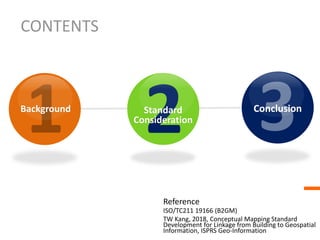
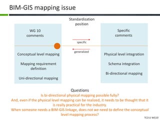
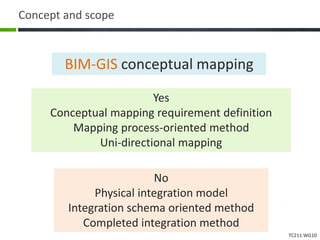
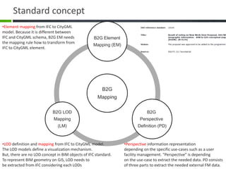
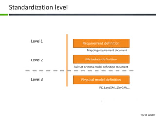
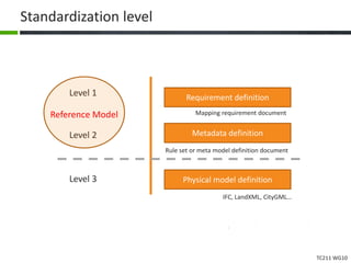
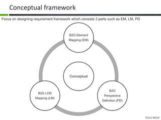
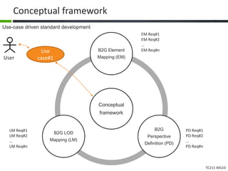
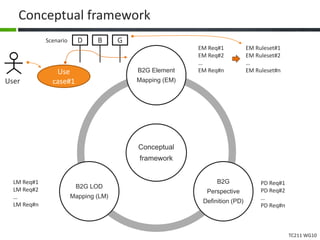
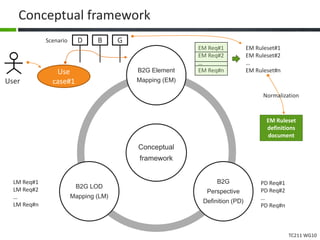
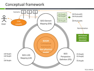
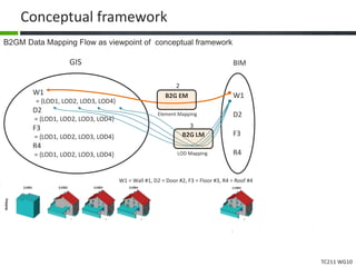
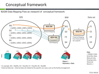
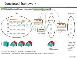
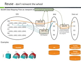
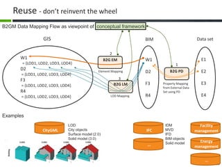
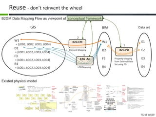
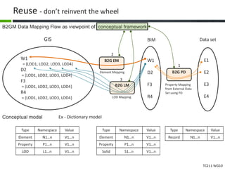
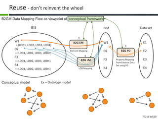
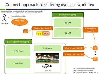
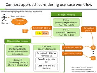
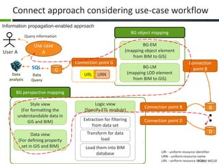
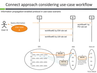
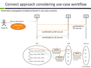
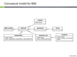
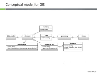
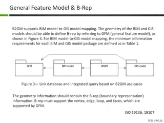
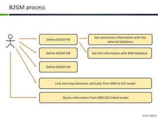
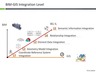
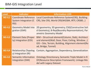
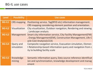
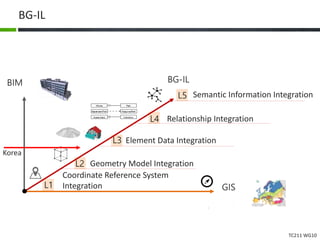
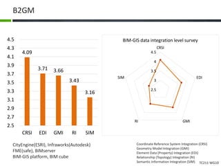
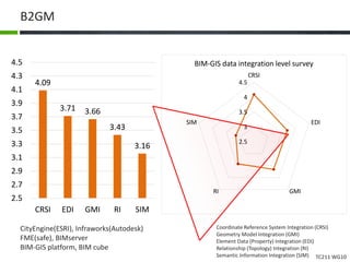
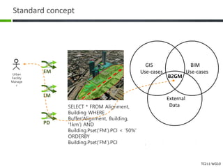
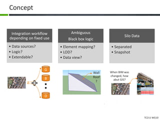
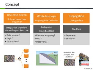
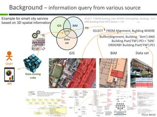
ISO/TC211
ISO 19166 B2GM
concept and description
2020.6
Ph.D, Tae wook, kang. Research Fellow, KICT
Interests – BIM, GIS, Vision, Interoperability
https://sites.google.com/site/bimprinciple/
laputa99999@gmail.com www.facebook.com/laputa999
CONTENTS
2Standard
Consideration
1Background Conclusion
Reference
ISO/TC211 19166 (B2GM)
TW Kang, 2018, Conceptual Mapping Standard
Development for Linkage from Building to Geospatial
Information, ISPRS Geo-Information
1 Background
TC211 WG10
Background – use cases
Level Use cases
1 Positioning service. Tag(RFID etc) information management.
CRS mapping considering element position and orientation.
2 City visualization, Outdoor navigation, Rendering and viewing, Landscape an
alysis.
3 Smart city information service, City Facility Management(FM), Energy Mana
gement(EM), Construction Management, Life-Cycle Cost Analysis(LCCA)
4 Composite navigation service, Evacuation simulation, Element Relationship-
based information query and navigation from city to building facility scale
5 Semantic information query, Data source reference identification and synchr
onization, knowledge development and management
TC211 WG10
Background - Unclear BIM-GIS integration process
• Unpredictable results
– It is difficult for the user to predict the model integration results.
• Missing data
– In the model integration process, the information necessary for the execution of use
case can be missed.
• Unnecessary management costs
– Information unnecessary for the execution of use case may be contained. The
unnecessary information may make the management of the integrated model difficult
and may increase the time and cost for the management thereof.
• Noise data
– Erroneous integrated noise information may lead to bad results in the execution of
service or in decision making.
To solve this problem, it’s better to be able to define the BIM-GIS integration
process in a standardized way from the point of view of use, and the result
should be clearly predictable
The problems mentioned may make the user hesitate to use the BIM-GIS model
integration information
TC211 WG10
ISO 19166 History
2013.5. IFC-to-CityGML physical model (schema level) mapping implement within specific
domain such as FM in 36th ISO TC211 Busan. In Busan, proposed element mapping table and
script, data view definition and binding with ETL, LoD generation by using solid operator(e.g.
extrude), raytracing, game rendering algorithm.
2014. 38th ISO TC211 meeting in Berin. Presented and shared IFC-to-CityGML mapping
technology, invited by ISO WG. This technology was proposed by the ISO WG 10 as NWIP
2015. NWIP works. Considering critical comments such as standard level and scope as the
viewpoint of ISO standardization, change them from physical model to conceptual mapping
2016.3. NWIP proposed and approved
2017. Resolved comments with WG
2018.11. CD proposed and 1st approved. Review comments in 47th ISO TC211 meeting
2019.5.13. CD 2nd approved.
2019.7.1. TS changed. CD approved. After meeting, we’ll propose DIS vote ASAP.
2020.6.30. 19166 should be published.
TC211 WG10
BIM-GIS mapping issue
Conceptual level mapping
Mapping requirement
definition
Uni-directional mapping
Physical level integration
Schema integration
Bi-directional mapping
Standardization
position
WG 10
comments
Specific
comments
Questions
Is bi-directional physical mapping possible fully?
And, even if the physical level mapping can be realized, it needs to be thought that it
is really practical for the industry.
When someone needs a BIM-GIS linkage, does not we need to define the conceptual
level mapping process?
generalized
specific
TC211 WG10
Philosophy
Complete data integration between heterogeneous models is impossible.
They have a structure developed for each purpose. However, the process of
selecting and connecting the necessary data from the use case perspective
can be explained.
TC211 WG10
Concept and scope
BIM-GIS conceptual mapping
No
Physical integration model
Integration schema oriented method
Completed integration method
Yes
Conceptual mapping requirement definition
Mapping process-oriented method
Uni-directional mapping
TC211 WG10
Request a proposal from ISO
2016/3
From 2014. DIN
ISO/TC211
meeting
TC211 WG10
Results
71 comments.
TMG: 16, ES: 15, GB: 9, US: 7…
Ge: 15, Ed: 21
TC211 WG10
Standard concept
B2G
Mapping
B2G Element
Mapping (EM)
B2G
Perspective
Definition (PD)
B2G LOD
Mapping
(LM)
•Element mapping from IFC to CityGML
model. Because it is different between
IFC and CityGML schema, B2G EM needs
the mapping rule how to transform from
IFC to CityGML element.
•LOD definition and mapping from IFC to CityGML model.
The LOD models define a visualization mechanism.
But, there are no LOD concept in BIM objects of IFC standard.
To represent BIM geometry on GIS, LOD needs to
be extracted from IFC considering each LODs
•Perspective information representation
depending on the specific use-cases such as a user
facility management. "Perspective" is depending
on the use-case to extract the needed data. PD consists
of three parts to extract the needed external FM data.
TC211 WG10
Standardization level
Metadata definition
Requirement definition
Physical model definition
Level 1
Level 2
Level 3
IFC, LandXML, CityGML…
Mapping requirement document
Rule set or meta model definition document
TC211 WG10
Standardization level
Metadata definition
Requirement definition
Physical model definition
Level 1
Level 2
Level 3
IFC, LandXML, CityGML…
Mapping requirement document
Rule set or meta model definition document
Reference Model
2 Standard
Consideration
for B2GM conceptual mapping standardization
TC211 WG10
Conceptual framework
Focus on designing requirement framework which consists 3 parts such as EM, LM, PD
Conceptual
B2G Element
Mapping (EM)
B2G
Perspective
Definition (PD)
B2G LOD
Mapping (LM)
TC211 WG10
Conceptual framework
Conceptual
framework
B2G Element
Mapping (EM)
B2G
Perspective
Definition (PD)
B2G LOD
Mapping (LM)
EM Req#1
EM Req#2
…
EM Req#n
PD Req#1
PD Req#2
…
PD Req#n
LM Req#1
LM Req#2
…
LM Req#n
Use-case driven standard development
User
Use
case#1
TC211 WG10
Conceptual framework
Conceptual
framework
B2G Element
Mapping (EM)
B2G
Perspective
Definition (PD)
B2G LOD
Mapping (LM)
EM Req#1
EM Req#2
…
EM Req#n
PD Req#1
PD Req#2
…
PD Req#n
LM Req#1
LM Req#2
…
LM Req#n
User
Use
case#1
EM Ruleset#1
EM Ruleset#2
…
EM Ruleset#n
B GDScenario
TC211 WG10
Conceptual framework
Conceptual
framework
B2G Element
Mapping (EM)
B2G
Perspective
Definition (PD)
B2G LOD
Mapping (LM)
EM Req#1
EM Req#2
…
EM Req#n
PD Req#1
PD Req#2
…
PD Req#n
LM Req#1
LM Req#2
…
LM Req#n
User
Use
case#1
EM Ruleset#1
EM Ruleset#2
…
EM Ruleset#n
B GDScenario
Normalization
EM Ruleset
definitions
document
TC211 WG10
Conceptual framework
Conceptual
framework
B2G Element
Mapping (EM)
B2G
Perspective
Definition (PD)
B2G LOD
Mapping (LM)
EM Req#1
EM Req#2
…
EM Req#n
PD Req#1
PD Req#2
…
PD Req#n
LM Req#1
LM Req#2
…
LM Req#n
User
Use
case#1
EM Ruleset#1
EM Ruleset#2
…
EM Ruleset#n
B GDScenario
B2GM
Not physical
model
Normalization
EM Ruleset
definitions
document
TC211 WG10
Conceptual framework
B2GM Data Mapping Flow as viewpoint of conceptual framework
BIM
W1
D2
F3
R4
GIS
W1
= {LOD1, LOD2, LOD3, LOD4}
D2
= {LOD1, LOD2, LOD3, LOD4}
F3
= {LOD1, LOD2, LOD3, LOD4}
R4
= {LOD1, LOD2, LOD3, LOD4}
B2G LM
B2G EM
W1 = Wall #1, D2 = Door #2, F3 = Floor #3, R4 = Roof #4
Element Mapping
LOD Mapping
2
3
TC211 WG10
Conceptual framework
B2GM Data Mapping Flow as viewpoint of conceptual framework
BIM
W1
D2
F3
R4
GIS
W1
= {LOD1, LOD2, LOD3, LOD4}
D2
= {LOD1, LOD2, LOD3, LOD4}
F3
= {LOD1, LOD2, LOD3, LOD4}
R4
= {LOD1, LOD2, LOD3, LOD4}
B2G LM
B2G EM
Data set
• In example, W1 = Wall#1, D2 = Door#2, F3 = Floor#3, R4 = Roof#4.
• External Data Set – External data set related to the specific use-cases such as the facility management
E1
E2
E3
E4
B2G PDElement Mapping
LOD Mapping
Property Mapping
from External Data
Set using PD
Data
= {Maker, Code,
Serial No, Date,
Manual Links,
Drawing Links,
Historical
Record…}
Object =
Geometry + Data
1
2
3
TC211 WG10
Reuse - don’t reinvent the wheel
B2GM Data Mapping Flow as viewpoint of conceptual framework
BIM
W1
D2
F3
R4
GIS
W1
= {LOD1, LOD2, LOD3, LOD4}
D2
= {LOD1, LOD2, LOD3, LOD4}
F3
= {LOD1, LOD2, LOD3, LOD4}
R4
= {LOD1, LOD2, LOD3, LOD4}
B2G LM
B2G EM
Data set
E1
E2
E3
E4
B2G PDElement Mapping
LOD Mapping
Property Mapping
from External Data
Set using PD
1
2
3
Energy
management
Facility
managementIFC
…
…
CityGML
Examples
IDM
MVD
IFD
BIM objects
Solid model
LOD
City objects
Surface model (2.0)
Solid model (3.0)
TC211 WG10
Reuse - don’t reinvent the wheel
B2GM Data Mapping Flow as viewpoint of conceptual framework
BIM
W1
D2
F3
R4
GIS
W1
= {LOD1, LOD2, LOD3, LOD4}
D2
= {LOD1, LOD2, LOD3, LOD4}
F3
= {LOD1, LOD2, LOD3, LOD4}
R4
= {LOD1, LOD2, LOD3, LOD4}
B2G LM
B2G EM
Data set
E1
E2
E3
E4
B2G PDElement Mapping
LOD Mapping
Property Mapping
from External Data
Set using PD
1
2
3
Existed physical model
Fig. IFC (http://www.iai-tech.org/)
IfcProject – Activity to make product
IfcProcess – Process and activity in project
IfcResource – Used resource object definition in process
IfcActor – Human resource definition in process
IfcProduct – Physical representation object
IfcControl – Control object
IfcGroup – Object set
Kernel
3개기본 확장 패키지
5개AEC/FM공통 패키지
AEC/FM도메인별9개의패키지
26개의 리소스패키지
IFC2x3
Building
Oriented
Format
IFC4
GIS CRS
NURBS
…
but
Heavy
Complex
Ambiguous
•Developed by OGC
•Open 3D urban object model for interoperability(ISO TC211)
•Shape, material, feature information support
•Focusing city Infrastructure object model
•Model abstraction support(LOD)Version 2.0
CityGML
GIS Oriented
Format
LOD
Features
But
Detailed
Building
Information?
Parameter set
Civil engineering
object
Detailed object
information
related to civil
engineering
ex- superelevation
LandXML
Civil
Engineering
Oriented
Format
But
Detailed
Building
Information?
GIS Topology
Element?
TC211 WG10
Reuse - don’t reinvent the wheel
B2GM Data Mapping Flow as viewpoint of conceptual framework
BIM
W1
D2
F3
R4
GIS
W1
= {LOD1, LOD2, LOD3, LOD4}
D2
= {LOD1, LOD2, LOD3, LOD4}
F3
= {LOD1, LOD2, LOD3, LOD4}
R4
= {LOD1, LOD2, LOD3, LOD4}
B2G LM
B2G EM
Data set
E1
E2
E3
E4
B2G PDElement Mapping
LOD Mapping
Property Mapping
from External Data
Set using PD
1
2
3
Conceptual model
Type Namespace Value
Element N1…n V1…n
Property P1…n V1…n
LOD L1…n V1…n
Type Namespace Value
Element N1…n V1…n
Property P1…n V1…n
Solid S1…n V1…n
Type Namespace Value
Record N1…n V1…n
Ex - Dictionary model
TC211 WG10
Reuse - don’t reinvent the wheel
B2GM Data Mapping Flow as viewpoint of conceptual framework
BIM
W1
D2
F3
R4
GIS
W1
= {LOD1, LOD2, LOD3, LOD4}
D2
= {LOD1, LOD2, LOD3, LOD4}
F3
= {LOD1, LOD2, LOD3, LOD4}
R4
= {LOD1, LOD2, LOD3, LOD4}
B2G LM
B2G EM
Data set
E1
E2
E3
E4
B2G PDElement Mapping
LOD Mapping
Property Mapping
from External Data
Set using PD
1
2
3
Conceptual model Ex – Ontology model
TC211 WG10
Connect approach considering use-case workflow
Information propagation-enabled approach
URI - uniform resource identifier
URN - uniform resource name
URL - uniform resource locator
User A
Use case
A
Query information
G
B
D
Connection
workflow
Connection point
URL URN
Query
TC211 WG10
Connect approach considering use-case workflow
Information propagation-enabled approach
URI - uniform resource identifier
URN - uniform resource name
URL - uniform resource locator
Logic view
User A
Use case
A
Query information
G
B
D
Data view
Style view
BG-EM
BG-LM
BG object mapping
BG perspective mapping
Connection point B
Connection point D
Connection point G
URL URN
Connection
point B
Data bus
TC211 WG10
Connect approach considering use-case workflow
Information propagation-enabled approach
URI - uniform resource identifier
URN - uniform resource name
URL - uniform resource locator
Logic view
(Specify ETL module)
User A
Use case
A
Query information
G
B
DTransform for data
load
Load them into BIM
database
Data view
(For defining property
schema in GIS and BIM)
Style view
(For formatting the
understandable data in
GIS and BIM)
BG-EM
(mapping object element
from BIM to GIS)
BG-LM
(mapping LOD element
from BIM to GIS)
Extraction for filtering
from data set
BG object mapping
BG perspective mapping
Connection point B
Connection point D
Connection point G
URL URN
Connection
point B
TC211 WG10
Connect approach considering use-case workflow
Information propagation-enabled approach
URI - uniform resource identifier
URN - uniform resource name
URL - uniform resource locator
Logic view
(Specify ETL module)
User A
Use case
A
Query information
G
B
DTransform for data
load
Load them into BIM
database
Data view
(For defining property
set in GIS and BIM)
Style view
(For formatting the
understandable data in
GIS and BIM)
BG-EM
(mapping object element
from BIM to GIS)
BG-LM
(mapping LOD element
from BIM to GIS)
Extraction for filtering
from data set
BG object mapping
BG perspective mapping
Connection point B
Connection point D
Connection point G
URL URN
Connection
point B
Data
analysis
Data
Query
SQL
TC211 WG10
Connect approach considering use-case workflow
Information propagation-enabled protocol in use-case scenario
User A
Use case
A
G
BIM
W1
D2
F3
R4
GIS
W1
= {LOD1, LOD2, LOD3, LOD4}
D2
= {LOD1, LOD2, LOD3, LOD4}
F3
= {LOD1, LOD2, LOD3, LOD4}
R4
= {LOD1, LOD2, LOD3, LOD4}
B2G LM
B2G EM
Data set
E1
E2
E3
E4
B2G PDElement Mapping
LOD Mapping
Property Mapping
fromExternal Data
Set using PD
1
2
3
B D
workflow#1 by
PD rule set
workflow#2 by EM rule set
workflow#3 by LM rule set
Query information
TC211 WG10
Connect approach considering use-case workflow
Information propagation-enabled protocol in use-case scenario
User B
Use case
B
G
BIM
W1
D2
F3
R4
GIS
W1
= {LOD1, LOD2, LOD3, LOD4}
D2
= {LOD1, LOD2, LOD3, LOD4}
F3
= {LOD1, LOD2, LOD3, LOD4}
R4
= {LOD1, LOD2, LOD3, LOD4}
B2G LM
B2G EM
Data set
E1
E2
E3
E4
B2G PDElement Mapping
LOD Mapping
Property Mapping
fromExternal Data
Set using PD
1
2
3
B D
workflow#4 by
PD rule set
workflow#5 by EM rule set
workflow#6 by LM rule set
Query information
TC211 WG10
Conceptual model for BIM
element geometryBIM_model * *
runtime
+type:string
property
+name: string
+type: {integer, real, string}
+value
*
B-rep
*
property_set
+name:string
+type: {system, general}
*relationship
+name: string
+type: {association, dependency, generalization}
*
TC211 WG10
Conceptual model for GIS
element geometryGIS_model * *
runtime
+type:string
property
+name: string
+type: {integer, real, string}
+value
*
B-rep
*
property_set
+name:string
+type: {system, general}
*relationship
+name: string
+type: {association, dependency, generalization}
*
LOD
+name: string
*
TC211 WG10
General Feature Model & B-Rep
B2GM supports BIM model-to-GIS model mapping. The geometry of the BIM and GIS
models should be able to define B-rep by referring to GFM (general feature model), as
shown in Figure 3. For BIM model-to-GIS model mapping, the minimum information
requirements for each BIM and GIS model package are defined as in Table 1.
B2GMGFM BIM model GIS model
Figure 3— Link database and Integrated query based on B2GM use cases
The geometry information should contain the B-rep (boundary representation)
information. B-rep must support the vertex, edge, loop, and faces, which are
supported by GFM.
ISO 19136, 19107
TC211 WG10
B-REP
Solid
+MakeShell()
+RemoveShell()
Face Surface
+Intersect()
Edge Curve
+Intersect()
Point
-x
-y
-z
Vertex
Shell
+MEL()
+KEL()
Loop
0..*
0..*
1..*
1..*
Line
Arc
Spline
B-Spline
NURBS
PlaneSurface B-SplineSurface NURBS-Surface
Euler formula example
MEL : Make an Edge and a Loop
KEL : Kill an Edge and a Loop
MVE : Make a Vertex and an Edge
Axis
+Position
+DirectionX
+DirectionY
TW, Kang. BIM
principle, 2011,
SpaceTime
pubisher
TC211 WG10
B-REP
Topology is the branch of mathematics describing the properties of objects which are
invariant under continuous deformation.
I.C.Braid, Designing with
Volumes, Computer-Aided
Design Group
TW, Kang. BIM principle, 2011,
SpaceTime pubisher
TC211 WG10
B-REP
ISO 19136, 19107
Topology is the branch of mathematics describing the properties of objects which are
invariant under continuous deformation.
Mantyla, M., Sulonen, R. "GWB: A solid modeler with Euler
operators", IEEE Computer graphics and applications, 1982
TC211 WG10
ISO 19136, 19107
ISO 19136, 19107
TC211 WG10
ISO 19136, 19107
TC211 WG10
Comments
TC211 WG10
ISO 19136, 19107
“GM_Solid” is represented by a “Solid”
object element in GML. The boundary
of a Solid is directly expressed
by “exterior” and “interior” properties
of the solid as discussed above.
TC211 WG10
TC211 WG10
B2GM process
Set connection information with the
external database
Set link information with BIM database
Define B2GM PD
Define B2GM EM
Define B2GM LM
Link and map elements and LoDs from BIM to GIS model
Query information from BIM-GIS linked model
TC211 WG10
BIM-GIS Integration Level
BIM
GIS
BG-IL
L5
L4
L3
L2
L1
Coordinate Reference System
Integration
Geometry Model Integration
Element Data Integration
Relationship Integration
Semantic Information Integration
TC211 WG10
BIM-GIS Integration Level
Level Indicator Information LOD
BG-IL1 Coordinate Reference
System Integration (C
RSI)
Local Coordinate Reference System(CRS), Building
CRS, Site CRS, World CRS(WGS84, IRTF, CRS80…)
BG-IL2 Geometry Model Inte
gration (GMI)
2D geomertry, 3D geometry, CSG(Constructive Soli
d Geometry), B-Rep(Boundry Representation), Par
ametric Geometry Model
BG-IL3 Element Data (Proper
ty) Integration (EDI)
BIM – Structrual element(Column, Slab), Architect
ural element(Wall, Door, Floor, Ceiling, Window…)
GIS – Site, Terrain, Building, Alignment element(Ro
ad, Bridge, Tunnel)
BG-IL4 Relationship (Topolog
y) Integration (RI)
Contain, Aggregation, Dependency, Generalization
BG-IL5 Semantic Information
Integration (SIM)
Ontology Directionary, Semantic Triple Model in R
DF(Resource Description Framework), Linkage Mo
del with Legacy Dataset
TC211 WG10
BG-IL use cases
Level Possibility Use cases
BG-IL1 CRS mapping Positioning service. Tag(RFID etc) information management.
CRS mapping considering element position and orientation.
BG-IL2 Visualization City visualization, Outdoor navigation, Rendering and viewing
, Landscape analysis.
BG-IL3 Management Smart city information service, City Facility Management(FM)
, Energy Management(EM), Construction Management, Life-C
ycle Cost Analysis(LCCA)
BG-IL4 Query and
simulation
Composite navigation service, Evacuation simulation, Elemen
t Relationship-based information query and navigation from c
ity to building facility scale
BG-IL5 Knowledge
mining
Semantic information query, Data source reference identificat
ion and synchronization, knowledge development and manag
ement
TC211 WG10
BG-IL
BIM
GIS
BG-IL
L5
L4
L3
L2
L1
Coordinate Reference System
Integration
Geometry Model Integration
Element Data Integration
Relationship Integration
Semantic Information Integration
Korea
TC211 WG10
B2GM
4.09
3.71 3.66
3.43
3.16
2.5
2.7
2.9
3.1
3.3
3.5
3.7
3.9
4.1
4.3
4.5
CRSI EDI GMI RI SIM
2.5
3
3.5
4
4.5
CRSI
EDI
GMIRI
SIM
BIM-GIS data integration level survey
Coordinate Reference System Integration (CRSI)
Geometry Model Integration (GMI)
Element Data (Property) Integration (EDI)
Relationship (Topology) Integration (RI)
Semantic Information Integration (SIM)
CityEngine(ESRI), Infraworks(Autodesk)
FME(safe), BIMserver
BIM-GIS platform, BIM cube
Conclusion
TC211 WG10
ISO TC211 standard organization
프레젠테이션 주제
Thanks for your interest
KICT
Ph.D Tae Wook, Kang(www.facebook.com/laputa999)
TC211 WG10
Standard concept
SELECT * FROM Alignment,
Building WHERE
Buffer(Alignment, Building,
‘1km’) AND
Building.Pset(‘FM’).PCI < ‘50%’
ORDERBY
Building.Pset(‘FM’).PCI
GIS
Use-cases
BIM
Use-cases
B2GM
External
Data
PD
EM
LM
Urban
Facility
Manage
r
TC211 WG10
Concept
Integration workflow
depending on fixed use
• Data sources?
• Logic?
• Extendable?
Ambiguous
Black box logic
• Element mapping?
• LOD?
• Data view?
Silo Data
• Separated
• Snapshot
G
B
D
Wall
Roof
?
When BIM was
changed, how
abut GIS?
TC211 WG10
Concept
Wall
Roof
?
When BIM was
changed, how
abut GIS?
Use case driven
Rule set based data
integration
White box logic
Mapping Rule Definition
Propagation
Linkage data
Integration workflow
depending on fixed use
• Data sources?
• Logic?
• Extendable?
Ambiguous
Black box logic
• Element mapping?
• LOD?
• Data view?
Silo Data
• Separated
• Snapshot
TC211 WG10
f(x)
bxayxf +=:)(
Background – information query from various source
SELECT * FROM Alignment, Building WHERE
Buffer(Alignment, Building, ‘1km’) AND
Building.Pset(‘FM’).PCI < ‘50%’
ORDERBY Building.Pset(‘FM’).PCI
BIMGIS
SELECT * FROM Building, Pipe WHERE Overlap(Pipe, Building, ‘1m’)
AND Building.Pset(‘FM’).Owner = ‘LH’ …
Fig. IFC (http://www.iai-tech.org/)
IfcProject – Activity to make product
IfcProcess – Process and activity in project
IfcResource – Used resource object definition in process
IfcActor – Human resource definition in process
IfcProduct – Physical representation object
IfcControl – Control object
IfcGroup – Object set
Kernel
3개기본 확장 패키지
5개AEC/FM공통 패키지
AEC/FM도메인별9개의패키지
26개의 리소스패키지
IFC2x3
Building
Oriented
Format
IFC4
GIS CRS
NURBS
…
but
Heavy
Complex
Ambiguous
•Developed by OGC
•Open 3D urban object model for interoperability(ISO TC211)
•Shape, material, feature information support
•Focusing city Infrastructure object model
•Model abstraction support(LOD)Version 2.0
CityGML
GIS Oriented
Format
LOD
Features
But
Detailed
Building
Information?
Parameter set
Civil engineering
object
Detailed object
information
related to civil
engineering
ex- superelevation
LandXML
Civil
Engineering
Oriented
Format
But
Detailed
Building
Information?
GIS Topology
Element?
GIS BIM
Data
set
Data set
Link
User
KPI
PD
Data mining
cube
Example for smart city service
based on 3D spatial information
TC211 WG10
Background – robotics based agent
Airmap
Here
unmanned autonomous car / drone
TC211 WG10
Background – city service
FIWARE
Virtual
Singapore
TC211 WG10
Background – spatial information service for smart city
Virtual Singapore
TC211 WG10
Introduce Ph.D Taewook Kang
Research Fellow. 11 books publish
https://sites.google.com/site/bimprinciple/

ISO 19166 BIM-GIS conceptual mapping

  • 1.
    ISO/TC211 ISO 19166 B2GM conceptand description 2020.6 Ph.D, Tae wook, kang. Research Fellow, KICT Interests – BIM, GIS, Vision, Interoperability https://sites.google.com/site/bimprinciple/ laputa99999@gmail.com www.facebook.com/laputa999
  • 2.
    CONTENTS 2Standard Consideration 1Background Conclusion Reference ISO/TC211 19166(B2GM) TW Kang, 2018, Conceptual Mapping Standard Development for Linkage from Building to Geospatial Information, ISPRS Geo-Information
  • 3.
  • 4.
    TC211 WG10 Background –use cases Level Use cases 1 Positioning service. Tag(RFID etc) information management. CRS mapping considering element position and orientation. 2 City visualization, Outdoor navigation, Rendering and viewing, Landscape an alysis. 3 Smart city information service, City Facility Management(FM), Energy Mana gement(EM), Construction Management, Life-Cycle Cost Analysis(LCCA) 4 Composite navigation service, Evacuation simulation, Element Relationship- based information query and navigation from city to building facility scale 5 Semantic information query, Data source reference identification and synchr onization, knowledge development and management
  • 5.
    TC211 WG10 Background -Unclear BIM-GIS integration process • Unpredictable results – It is difficult for the user to predict the model integration results. • Missing data – In the model integration process, the information necessary for the execution of use case can be missed. • Unnecessary management costs – Information unnecessary for the execution of use case may be contained. The unnecessary information may make the management of the integrated model difficult and may increase the time and cost for the management thereof. • Noise data – Erroneous integrated noise information may lead to bad results in the execution of service or in decision making. To solve this problem, it’s better to be able to define the BIM-GIS integration process in a standardized way from the point of view of use, and the result should be clearly predictable The problems mentioned may make the user hesitate to use the BIM-GIS model integration information
  • 6.
    TC211 WG10 ISO 19166History 2013.5. IFC-to-CityGML physical model (schema level) mapping implement within specific domain such as FM in 36th ISO TC211 Busan. In Busan, proposed element mapping table and script, data view definition and binding with ETL, LoD generation by using solid operator(e.g. extrude), raytracing, game rendering algorithm. 2014. 38th ISO TC211 meeting in Berin. Presented and shared IFC-to-CityGML mapping technology, invited by ISO WG. This technology was proposed by the ISO WG 10 as NWIP 2015. NWIP works. Considering critical comments such as standard level and scope as the viewpoint of ISO standardization, change them from physical model to conceptual mapping 2016.3. NWIP proposed and approved 2017. Resolved comments with WG 2018.11. CD proposed and 1st approved. Review comments in 47th ISO TC211 meeting 2019.5.13. CD 2nd approved. 2019.7.1. TS changed. CD approved. After meeting, we’ll propose DIS vote ASAP. 2020.6.30. 19166 should be published.
  • 7.
    TC211 WG10 BIM-GIS mappingissue Conceptual level mapping Mapping requirement definition Uni-directional mapping Physical level integration Schema integration Bi-directional mapping Standardization position WG 10 comments Specific comments Questions Is bi-directional physical mapping possible fully? And, even if the physical level mapping can be realized, it needs to be thought that it is really practical for the industry. When someone needs a BIM-GIS linkage, does not we need to define the conceptual level mapping process? generalized specific
  • 8.
    TC211 WG10 Philosophy Complete dataintegration between heterogeneous models is impossible. They have a structure developed for each purpose. However, the process of selecting and connecting the necessary data from the use case perspective can be explained.
  • 9.
    TC211 WG10 Concept andscope BIM-GIS conceptual mapping No Physical integration model Integration schema oriented method Completed integration method Yes Conceptual mapping requirement definition Mapping process-oriented method Uni-directional mapping
  • 10.
    TC211 WG10 Request aproposal from ISO 2016/3 From 2014. DIN ISO/TC211 meeting
  • 11.
    TC211 WG10 Results 71 comments. TMG:16, ES: 15, GB: 9, US: 7… Ge: 15, Ed: 21
  • 12.
    TC211 WG10 Standard concept B2G Mapping B2GElement Mapping (EM) B2G Perspective Definition (PD) B2G LOD Mapping (LM) •Element mapping from IFC to CityGML model. Because it is different between IFC and CityGML schema, B2G EM needs the mapping rule how to transform from IFC to CityGML element. •LOD definition and mapping from IFC to CityGML model. The LOD models define a visualization mechanism. But, there are no LOD concept in BIM objects of IFC standard. To represent BIM geometry on GIS, LOD needs to be extracted from IFC considering each LODs •Perspective information representation depending on the specific use-cases such as a user facility management. "Perspective" is depending on the use-case to extract the needed data. PD consists of three parts to extract the needed external FM data.
  • 13.
    TC211 WG10 Standardization level Metadatadefinition Requirement definition Physical model definition Level 1 Level 2 Level 3 IFC, LandXML, CityGML… Mapping requirement document Rule set or meta model definition document
  • 14.
    TC211 WG10 Standardization level Metadatadefinition Requirement definition Physical model definition Level 1 Level 2 Level 3 IFC, LandXML, CityGML… Mapping requirement document Rule set or meta model definition document Reference Model
  • 15.
    2 Standard Consideration for B2GMconceptual mapping standardization
  • 16.
    TC211 WG10 Conceptual framework Focuson designing requirement framework which consists 3 parts such as EM, LM, PD Conceptual B2G Element Mapping (EM) B2G Perspective Definition (PD) B2G LOD Mapping (LM)
  • 17.
    TC211 WG10 Conceptual framework Conceptual framework B2GElement Mapping (EM) B2G Perspective Definition (PD) B2G LOD Mapping (LM) EM Req#1 EM Req#2 … EM Req#n PD Req#1 PD Req#2 … PD Req#n LM Req#1 LM Req#2 … LM Req#n Use-case driven standard development User Use case#1
  • 18.
    TC211 WG10 Conceptual framework Conceptual framework B2GElement Mapping (EM) B2G Perspective Definition (PD) B2G LOD Mapping (LM) EM Req#1 EM Req#2 … EM Req#n PD Req#1 PD Req#2 … PD Req#n LM Req#1 LM Req#2 … LM Req#n User Use case#1 EM Ruleset#1 EM Ruleset#2 … EM Ruleset#n B GDScenario
  • 19.
    TC211 WG10 Conceptual framework Conceptual framework B2GElement Mapping (EM) B2G Perspective Definition (PD) B2G LOD Mapping (LM) EM Req#1 EM Req#2 … EM Req#n PD Req#1 PD Req#2 … PD Req#n LM Req#1 LM Req#2 … LM Req#n User Use case#1 EM Ruleset#1 EM Ruleset#2 … EM Ruleset#n B GDScenario Normalization EM Ruleset definitions document
  • 20.
    TC211 WG10 Conceptual framework Conceptual framework B2GElement Mapping (EM) B2G Perspective Definition (PD) B2G LOD Mapping (LM) EM Req#1 EM Req#2 … EM Req#n PD Req#1 PD Req#2 … PD Req#n LM Req#1 LM Req#2 … LM Req#n User Use case#1 EM Ruleset#1 EM Ruleset#2 … EM Ruleset#n B GDScenario B2GM Not physical model Normalization EM Ruleset definitions document
  • 21.
    TC211 WG10 Conceptual framework B2GMData Mapping Flow as viewpoint of conceptual framework BIM W1 D2 F3 R4 GIS W1 = {LOD1, LOD2, LOD3, LOD4} D2 = {LOD1, LOD2, LOD3, LOD4} F3 = {LOD1, LOD2, LOD3, LOD4} R4 = {LOD1, LOD2, LOD3, LOD4} B2G LM B2G EM W1 = Wall #1, D2 = Door #2, F3 = Floor #3, R4 = Roof #4 Element Mapping LOD Mapping 2 3
  • 22.
    TC211 WG10 Conceptual framework B2GMData Mapping Flow as viewpoint of conceptual framework BIM W1 D2 F3 R4 GIS W1 = {LOD1, LOD2, LOD3, LOD4} D2 = {LOD1, LOD2, LOD3, LOD4} F3 = {LOD1, LOD2, LOD3, LOD4} R4 = {LOD1, LOD2, LOD3, LOD4} B2G LM B2G EM Data set • In example, W1 = Wall#1, D2 = Door#2, F3 = Floor#3, R4 = Roof#4. • External Data Set – External data set related to the specific use-cases such as the facility management E1 E2 E3 E4 B2G PDElement Mapping LOD Mapping Property Mapping from External Data Set using PD Data = {Maker, Code, Serial No, Date, Manual Links, Drawing Links, Historical Record…} Object = Geometry + Data 1 2 3
  • 23.
    TC211 WG10 Conceptual framework B2GMData Mapping Flow as viewpoint of conceptual framework BIM W1 D2 F3 R4 GIS W1 = {LOD1, LOD2, LOD3, LOD4} D2 = {LOD1, LOD2, LOD3, LOD4} F3 = {LOD1, LOD2, LOD3, LOD4} R4 = {LOD1, LOD2, LOD3, LOD4} B2G LM B2G EM Data set • In example, W1 = Wall#1, D2 = Door#2, F3 = Floor#3, R4 = Roof#4. • External Data Set – External data set related to the specific use-cases such as the facility management E1 E2 E3 E4 B2G PDElement Mapping LOD Mapping Property Mapping from External Data Set using PD Data = {Maker, Code, Serial No, Date, Manual Links, Drawing Links, Historical Record…} Object = Geometry + Data 1 2 3
  • 24.
    TC211 WG10 Reuse -don’t reinvent the wheel B2GM Data Mapping Flow as viewpoint of conceptual framework BIM W1 D2 F3 R4 GIS W1 = {LOD1, LOD2, LOD3, LOD4} D2 = {LOD1, LOD2, LOD3, LOD4} F3 = {LOD1, LOD2, LOD3, LOD4} R4 = {LOD1, LOD2, LOD3, LOD4} B2G LM B2G EM Data set E1 E2 E3 E4 B2G PDElement Mapping LOD Mapping Property Mapping from External Data Set using PD 1 2 3 Energy management Facility managementIFC … … CityGML Examples
  • 25.
    TC211 WG10 Reuse -don’t reinvent the wheel B2GM Data Mapping Flow as viewpoint of conceptual framework BIM W1 D2 F3 R4 GIS W1 = {LOD1, LOD2, LOD3, LOD4} D2 = {LOD1, LOD2, LOD3, LOD4} F3 = {LOD1, LOD2, LOD3, LOD4} R4 = {LOD1, LOD2, LOD3, LOD4} B2G LM B2G EM Data set E1 E2 E3 E4 B2G PDElement Mapping LOD Mapping Property Mapping from External Data Set using PD 1 2 3 Energy management Facility managementIFC … … CityGML Examples IDM MVD IFD BIM objects Solid model LOD City objects Surface model (2.0) Solid model (3.0)
  • 26.
    TC211 WG10 Reuse -don’t reinvent the wheel B2GM Data Mapping Flow as viewpoint of conceptual framework BIM W1 D2 F3 R4 GIS W1 = {LOD1, LOD2, LOD3, LOD4} D2 = {LOD1, LOD2, LOD3, LOD4} F3 = {LOD1, LOD2, LOD3, LOD4} R4 = {LOD1, LOD2, LOD3, LOD4} B2G LM B2G EM Data set E1 E2 E3 E4 B2G PDElement Mapping LOD Mapping Property Mapping from External Data Set using PD 1 2 3 Existed physical model Fig. IFC (http://www.iai-tech.org/) IfcProject – Activity to make product IfcProcess – Process and activity in project IfcResource – Used resource object definition in process IfcActor – Human resource definition in process IfcProduct – Physical representation object IfcControl – Control object IfcGroup – Object set Kernel 3개기본 확장 패키지 5개AEC/FM공통 패키지 AEC/FM도메인별9개의패키지 26개의 리소스패키지 IFC2x3 Building Oriented Format IFC4 GIS CRS NURBS … but Heavy Complex Ambiguous •Developed by OGC •Open 3D urban object model for interoperability(ISO TC211) •Shape, material, feature information support •Focusing city Infrastructure object model •Model abstraction support(LOD)Version 2.0 CityGML GIS Oriented Format LOD Features But Detailed Building Information? Parameter set Civil engineering object Detailed object information related to civil engineering ex- superelevation LandXML Civil Engineering Oriented Format But Detailed Building Information? GIS Topology Element?
  • 27.
    TC211 WG10 Reuse -don’t reinvent the wheel B2GM Data Mapping Flow as viewpoint of conceptual framework BIM W1 D2 F3 R4 GIS W1 = {LOD1, LOD2, LOD3, LOD4} D2 = {LOD1, LOD2, LOD3, LOD4} F3 = {LOD1, LOD2, LOD3, LOD4} R4 = {LOD1, LOD2, LOD3, LOD4} B2G LM B2G EM Data set E1 E2 E3 E4 B2G PDElement Mapping LOD Mapping Property Mapping from External Data Set using PD 1 2 3 Conceptual model Type Namespace Value Element N1…n V1…n Property P1…n V1…n LOD L1…n V1…n Type Namespace Value Element N1…n V1…n Property P1…n V1…n Solid S1…n V1…n Type Namespace Value Record N1…n V1…n Ex - Dictionary model
  • 28.
    TC211 WG10 Reuse -don’t reinvent the wheel B2GM Data Mapping Flow as viewpoint of conceptual framework BIM W1 D2 F3 R4 GIS W1 = {LOD1, LOD2, LOD3, LOD4} D2 = {LOD1, LOD2, LOD3, LOD4} F3 = {LOD1, LOD2, LOD3, LOD4} R4 = {LOD1, LOD2, LOD3, LOD4} B2G LM B2G EM Data set E1 E2 E3 E4 B2G PDElement Mapping LOD Mapping Property Mapping from External Data Set using PD 1 2 3 Conceptual model Ex – Ontology model
  • 29.
    TC211 WG10 Connect approachconsidering use-case workflow Information propagation-enabled approach URI - uniform resource identifier URN - uniform resource name URL - uniform resource locator User A Use case A Query information G B D Connection workflow Connection point URL URN Query
  • 30.
    TC211 WG10 Connect approachconsidering use-case workflow Information propagation-enabled approach URI - uniform resource identifier URN - uniform resource name URL - uniform resource locator Logic view User A Use case A Query information G B D Data view Style view BG-EM BG-LM BG object mapping BG perspective mapping Connection point B Connection point D Connection point G URL URN Connection point B Data bus
  • 31.
    TC211 WG10 Connect approachconsidering use-case workflow Information propagation-enabled approach URI - uniform resource identifier URN - uniform resource name URL - uniform resource locator Logic view (Specify ETL module) User A Use case A Query information G B DTransform for data load Load them into BIM database Data view (For defining property schema in GIS and BIM) Style view (For formatting the understandable data in GIS and BIM) BG-EM (mapping object element from BIM to GIS) BG-LM (mapping LOD element from BIM to GIS) Extraction for filtering from data set BG object mapping BG perspective mapping Connection point B Connection point D Connection point G URL URN Connection point B
  • 32.
    TC211 WG10 Connect approachconsidering use-case workflow Information propagation-enabled approach URI - uniform resource identifier URN - uniform resource name URL - uniform resource locator Logic view (Specify ETL module) User A Use case A Query information G B DTransform for data load Load them into BIM database Data view (For defining property set in GIS and BIM) Style view (For formatting the understandable data in GIS and BIM) BG-EM (mapping object element from BIM to GIS) BG-LM (mapping LOD element from BIM to GIS) Extraction for filtering from data set BG object mapping BG perspective mapping Connection point B Connection point D Connection point G URL URN Connection point B Data analysis Data Query SQL
  • 33.
    TC211 WG10 Connect approachconsidering use-case workflow Information propagation-enabled protocol in use-case scenario User A Use case A G BIM W1 D2 F3 R4 GIS W1 = {LOD1, LOD2, LOD3, LOD4} D2 = {LOD1, LOD2, LOD3, LOD4} F3 = {LOD1, LOD2, LOD3, LOD4} R4 = {LOD1, LOD2, LOD3, LOD4} B2G LM B2G EM Data set E1 E2 E3 E4 B2G PDElement Mapping LOD Mapping Property Mapping fromExternal Data Set using PD 1 2 3 B D workflow#1 by PD rule set workflow#2 by EM rule set workflow#3 by LM rule set Query information
  • 34.
    TC211 WG10 Connect approachconsidering use-case workflow Information propagation-enabled protocol in use-case scenario User B Use case B G BIM W1 D2 F3 R4 GIS W1 = {LOD1, LOD2, LOD3, LOD4} D2 = {LOD1, LOD2, LOD3, LOD4} F3 = {LOD1, LOD2, LOD3, LOD4} R4 = {LOD1, LOD2, LOD3, LOD4} B2G LM B2G EM Data set E1 E2 E3 E4 B2G PDElement Mapping LOD Mapping Property Mapping fromExternal Data Set using PD 1 2 3 B D workflow#4 by PD rule set workflow#5 by EM rule set workflow#6 by LM rule set Query information
  • 35.
    TC211 WG10 Conceptual modelfor BIM element geometryBIM_model * * runtime +type:string property +name: string +type: {integer, real, string} +value * B-rep * property_set +name:string +type: {system, general} *relationship +name: string +type: {association, dependency, generalization} *
  • 36.
    TC211 WG10 Conceptual modelfor GIS element geometryGIS_model * * runtime +type:string property +name: string +type: {integer, real, string} +value * B-rep * property_set +name:string +type: {system, general} *relationship +name: string +type: {association, dependency, generalization} * LOD +name: string *
  • 37.
    TC211 WG10 General FeatureModel & B-Rep B2GM supports BIM model-to-GIS model mapping. The geometry of the BIM and GIS models should be able to define B-rep by referring to GFM (general feature model), as shown in Figure 3. For BIM model-to-GIS model mapping, the minimum information requirements for each BIM and GIS model package are defined as in Table 1. B2GMGFM BIM model GIS model Figure 3— Link database and Integrated query based on B2GM use cases The geometry information should contain the B-rep (boundary representation) information. B-rep must support the vertex, edge, loop, and faces, which are supported by GFM. ISO 19136, 19107
  • 38.
    TC211 WG10 B-REP Solid +MakeShell() +RemoveShell() Face Surface +Intersect() EdgeCurve +Intersect() Point -x -y -z Vertex Shell +MEL() +KEL() Loop 0..* 0..* 1..* 1..* Line Arc Spline B-Spline NURBS PlaneSurface B-SplineSurface NURBS-Surface Euler formula example MEL : Make an Edge and a Loop KEL : Kill an Edge and a Loop MVE : Make a Vertex and an Edge Axis +Position +DirectionX +DirectionY TW, Kang. BIM principle, 2011, SpaceTime pubisher
  • 39.
    TC211 WG10 B-REP Topology isthe branch of mathematics describing the properties of objects which are invariant under continuous deformation. I.C.Braid, Designing with Volumes, Computer-Aided Design Group TW, Kang. BIM principle, 2011, SpaceTime pubisher
  • 40.
    TC211 WG10 B-REP ISO 19136,19107 Topology is the branch of mathematics describing the properties of objects which are invariant under continuous deformation. Mantyla, M., Sulonen, R. "GWB: A solid modeler with Euler operators", IEEE Computer graphics and applications, 1982
  • 41.
    TC211 WG10 ISO 19136,19107 ISO 19136, 19107
  • 42.
  • 43.
  • 44.
    TC211 WG10 ISO 19136,19107 “GM_Solid” is represented by a “Solid” object element in GML. The boundary of a Solid is directly expressed by “exterior” and “interior” properties of the solid as discussed above.
  • 45.
  • 46.
    TC211 WG10 B2GM process Setconnection information with the external database Set link information with BIM database Define B2GM PD Define B2GM EM Define B2GM LM Link and map elements and LoDs from BIM to GIS model Query information from BIM-GIS linked model
  • 47.
    TC211 WG10 BIM-GIS IntegrationLevel BIM GIS BG-IL L5 L4 L3 L2 L1 Coordinate Reference System Integration Geometry Model Integration Element Data Integration Relationship Integration Semantic Information Integration
  • 48.
    TC211 WG10 BIM-GIS IntegrationLevel Level Indicator Information LOD BG-IL1 Coordinate Reference System Integration (C RSI) Local Coordinate Reference System(CRS), Building CRS, Site CRS, World CRS(WGS84, IRTF, CRS80…) BG-IL2 Geometry Model Inte gration (GMI) 2D geomertry, 3D geometry, CSG(Constructive Soli d Geometry), B-Rep(Boundry Representation), Par ametric Geometry Model BG-IL3 Element Data (Proper ty) Integration (EDI) BIM – Structrual element(Column, Slab), Architect ural element(Wall, Door, Floor, Ceiling, Window…) GIS – Site, Terrain, Building, Alignment element(Ro ad, Bridge, Tunnel) BG-IL4 Relationship (Topolog y) Integration (RI) Contain, Aggregation, Dependency, Generalization BG-IL5 Semantic Information Integration (SIM) Ontology Directionary, Semantic Triple Model in R DF(Resource Description Framework), Linkage Mo del with Legacy Dataset
  • 49.
    TC211 WG10 BG-IL usecases Level Possibility Use cases BG-IL1 CRS mapping Positioning service. Tag(RFID etc) information management. CRS mapping considering element position and orientation. BG-IL2 Visualization City visualization, Outdoor navigation, Rendering and viewing , Landscape analysis. BG-IL3 Management Smart city information service, City Facility Management(FM) , Energy Management(EM), Construction Management, Life-C ycle Cost Analysis(LCCA) BG-IL4 Query and simulation Composite navigation service, Evacuation simulation, Elemen t Relationship-based information query and navigation from c ity to building facility scale BG-IL5 Knowledge mining Semantic information query, Data source reference identificat ion and synchronization, knowledge development and manag ement
  • 50.
    TC211 WG10 BG-IL BIM GIS BG-IL L5 L4 L3 L2 L1 Coordinate ReferenceSystem Integration Geometry Model Integration Element Data Integration Relationship Integration Semantic Information Integration Korea
  • 51.
    TC211 WG10 B2GM 4.09 3.71 3.66 3.43 3.16 2.5 2.7 2.9 3.1 3.3 3.5 3.7 3.9 4.1 4.3 4.5 CRSIEDI GMI RI SIM 2.5 3 3.5 4 4.5 CRSI EDI GMIRI SIM BIM-GIS data integration level survey Coordinate Reference System Integration (CRSI) Geometry Model Integration (GMI) Element Data (Property) Integration (EDI) Relationship (Topology) Integration (RI) Semantic Information Integration (SIM) CityEngine(ESRI), Infraworks(Autodesk) FME(safe), BIMserver BIM-GIS platform, BIM cube
  • 52.
    TC211 WG10 B2GM 4.09 3.71 3.66 3.43 3.16 2.5 2.7 2.9 3.1 3.3 3.5 3.7 3.9 4.1 4.3 4.5 CRSIEDI GMI RI SIM 2.5 3 3.5 4 4.5 CRSI EDI GMIRI SIM BIM-GIS data integration level survey Coordinate Reference System Integration (CRSI) Geometry Model Integration (GMI) Element Data (Property) Integration (EDI) Relationship (Topology) Integration (RI) Semantic Information Integration (SIM) CityEngine(ESRI), Infraworks(Autodesk) FME(safe), BIMserver BIM-GIS platform, BIM cube
  • 53.
  • 54.
    TC211 WG10 ISO TC211standard organization
  • 55.
    프레젠테이션 주제 Thanks foryour interest KICT Ph.D Tae Wook, Kang(www.facebook.com/laputa999)
  • 56.
    TC211 WG10 Standard concept SELECT* FROM Alignment, Building WHERE Buffer(Alignment, Building, ‘1km’) AND Building.Pset(‘FM’).PCI < ‘50%’ ORDERBY Building.Pset(‘FM’).PCI GIS Use-cases BIM Use-cases B2GM External Data PD EM LM Urban Facility Manage r
  • 57.
    TC211 WG10 Concept Integration workflow dependingon fixed use • Data sources? • Logic? • Extendable? Ambiguous Black box logic • Element mapping? • LOD? • Data view? Silo Data • Separated • Snapshot G B D Wall Roof ? When BIM was changed, how abut GIS?
  • 58.
    TC211 WG10 Concept Wall Roof ? When BIMwas changed, how abut GIS? Use case driven Rule set based data integration White box logic Mapping Rule Definition Propagation Linkage data Integration workflow depending on fixed use • Data sources? • Logic? • Extendable? Ambiguous Black box logic • Element mapping? • LOD? • Data view? Silo Data • Separated • Snapshot
  • 59.
    TC211 WG10 f(x) bxayxf +=:)( Background– information query from various source SELECT * FROM Alignment, Building WHERE Buffer(Alignment, Building, ‘1km’) AND Building.Pset(‘FM’).PCI < ‘50%’ ORDERBY Building.Pset(‘FM’).PCI BIMGIS SELECT * FROM Building, Pipe WHERE Overlap(Pipe, Building, ‘1m’) AND Building.Pset(‘FM’).Owner = ‘LH’ … Fig. IFC (http://www.iai-tech.org/) IfcProject – Activity to make product IfcProcess – Process and activity in project IfcResource – Used resource object definition in process IfcActor – Human resource definition in process IfcProduct – Physical representation object IfcControl – Control object IfcGroup – Object set Kernel 3개기본 확장 패키지 5개AEC/FM공통 패키지 AEC/FM도메인별9개의패키지 26개의 리소스패키지 IFC2x3 Building Oriented Format IFC4 GIS CRS NURBS … but Heavy Complex Ambiguous •Developed by OGC •Open 3D urban object model for interoperability(ISO TC211) •Shape, material, feature information support •Focusing city Infrastructure object model •Model abstraction support(LOD)Version 2.0 CityGML GIS Oriented Format LOD Features But Detailed Building Information? Parameter set Civil engineering object Detailed object information related to civil engineering ex- superelevation LandXML Civil Engineering Oriented Format But Detailed Building Information? GIS Topology Element? GIS BIM Data set Data set Link User KPI PD Data mining cube Example for smart city service based on 3D spatial information
  • 60.
    TC211 WG10 Background –robotics based agent Airmap Here unmanned autonomous car / drone
  • 61.
    TC211 WG10 Background –city service FIWARE Virtual Singapore
  • 62.
    TC211 WG10 Background –spatial information service for smart city Virtual Singapore
  • 63.
    TC211 WG10 Introduce Ph.DTaewook Kang Research Fellow. 11 books publish https://sites.google.com/site/bimprinciple/