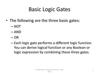
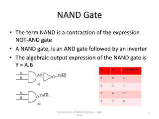
2. Logic Circuits
• A collection of individual logic gates connect with
each other and produce a logic design known as a
Logic Circuit
• The following are the types of logic circuits:
– Decision making
– Memory
– A gate has two or more binary inputs and single output.
2
Fundamentals of Digital Electronics - Logic
Gates
3. Basic Logic Gates
• The following are the three basic gates:
– NOT
– AND
– OR
– Each logic gate performs a different logic function.
You can derive logical function or any Boolean or
logic expression by combining these three gates.
Fundamentals of Digital Electronics - Logic
Gates
3
4. NOT Gate
• The simplest form of a digital logic circuit is the
inverter or the NOT gate
• It consists of one input and one output and the input
can only be binary numbers namely; 0 and 1
the truth table for NOT Gate:
Fundamentals of Digital Electronics - Logic
Gates
4
5. AND Gate
• The AND gate is a logic circuit that has two or more inputs and
a single output
• The operation of the gate is such that the output of the gate is
a binary 1 if and only if all inputs are binary 1
• Similarly, if any one or more inputs are binary 0, the output
will be binary 0.
Fundamentals of Digital Electronics - Logic
Gates
5
6. OR Gate
• The OR gate is another basic logic gate
• Like the AND gate, it can have two or more inputs and a single
output
• The operation of OR gate is such that the output is a binary 1
if any one or all inputs are binary 1 and the output is binary 0
only when all the inputs are binary 0
Fundamentals of Digital Electronics - Logic
Gates
6
7. NAND Gate
• The term NAND is a contraction of the expression
NOT-AND gate
• A NAND gate, is an AND gate followed by an inverter
• The algebraic output expression of the NAND gate is
Y = A.B
Fundamentals of Digital Electronics - Logic
Gates
7
8. NOR Gate
• The term NOR is a contradiction of the expression
NOT-OR
• A NOR gate, is an OR gate followed by an inverter
• The algebraic output expression of the NOR gate is Y
= A + B
Fundamentals of Digital Electronics - Logic
Gates
8
9. EX-OR and EX-NOR Gates
• EX-OR and EX-NOR are digital logic circuits
that may use two or more inputs
• EX-NOR gate returns the output opposite to
EX-OR gate
• EX-OR and EX-NOR gates are also denoted by
XOR and XNOR respectively.
Fundamentals of Digital Electronics - Logic
Gates
9
10. EXOR Gate
• The Ex-OR (Exclusive- OR) gate returns high output with one of two high
inputs (but not with both high inputs or both low inputs)
• For example, if both the inputs are binary 0 or 1, it will return the output
as 0. Similarly, if one input is binary 1 and another is binary 0, the output
will be 1 (high)
• The operation for the Ex-OR gate is denoted by encircled plus symbol
• The Ex-OR operation is widely used in digital circuits.
• The algebraic output expression of the Ex-OR gate is Y = A ⊕ B =
Fundamentals of Digital Electronics - Logic
Gates
10
11. EXNOR Gate
• The Ex-NOR (Exclusive- NOR) gate is a circuit that returns low output with
one of two high inputs (but not with both high inputs)
• For example, if both the inputs are binary 0 or 1, it will return the output
as 1. Similarly, if one input is binary 1 and another is binary 0, the output
will be 0 (low)
• The symbol for the Ex-NOR gate is denoted by encircled plus symbol which
inverts the binary values
• The algebraic output expression of the Ex-NOR gate is Y =
Fundamentals of Digital Electronics - Logic
Gates
11
12. Applications of Logic Gates
• The following are some of the applications of Logic
gates:
– Build complex systems that can be used to different fields
such as
• Genetic engineering,
• Nanotechnology,
• Industrial Fermentation,
• Metabolic engineering and
• Medicine
– Construct multiplexers, adders and multipliers.
– Perform several parallel logical operations
– Used for a simple house alarm or fire alarm or in the circuit
of automated machine manufacturing industry
Fundamentals of Digital Electronics - Logic
Gates
12