SlideShare a Scribd company logo
International Research Journal of Engineering and Technology (IRJET) e-ISSN: 2395-0056
Volume: 05 Issue: 11 | Nov 2018 www.irjet.net p-ISSN: 2395-0072
© 2018, IRJET | Impact Factor value: 7.211 | ISO 9001:2008 Certified Journal | Page 1768
Numerical Analysis of Industrial Roll Cooling using FEM
Chandan Prasad1, Subhashree Pothal2
1M.Tech Scholar, Mettalurgical & Materials Engineering, NIT Durgapur, West Bengal, India
2Assistant Professor, Department of Mechanical Engineering, REC, Bhubaneswar, Odisha, India
----------------------------------------------------------------------***---------------------------------------------------------------------
Abstract:- In a hot strip mill, the quality of the rolled products and the productivity of the mill depend on the efficiency of roll
cooling to a great extent. Tostudy the influence of the cooling system on roll performance, a good understanding of the thermal
aspects of roll cooling is essential. Mathematical models to predict temperature development in the work roll induced at the roll
surface during rolling were developed. The models were used to predict temperatures in the roll under various cooling conditions,
thus examining the efficiency of the existing roll cooling system and exploring the scope of optimizing it.
Keywords— Roll Wear, Roll; Hot Strip Mil, Roll Cooling;
1. INTRODUCTION
To meet the high quality requirements of nowadays steel production, it is vital that the rolling takes place in the prescribed
temperature range. Moreover, the temperature largely influences the yield stress and thus the rolling force and torque.
Therefore, the temperature evolution of the plate has to be considered when planning theroll passesandschedulingthewhole
production process. In the following, the different production steps are outlined by means of an overview of the considered
rolling mill shown in Figure 1 and their influence on the temperature evolution of the plate is briefly described. In hot rolling,
wear of the work roll takes place mainly because of:
I. Abrasion of the roll surface due to contact with the strip, and in a four high mill, due to contact with the back-up roll
also
II. Fatigue of the surface layers due to the variable nature of mechanical stressesapplied bythestripandtheback-uproll
III. Thermal fatigue of the roll surface due to the temperature cycles undergone by the outer layers as those are
alternately heated by the strip and cooled by the coolant from the spray headers.
Fig. 1.Cooling arrangement for work rolls rolling a slab/strip (Back-up rolls and cooling of the lower work roll not shown).
International Research Journal of Engineering and Technology (IRJET) e-ISSN: 2395-0056
Volume: 05 Issue: 11 | Nov 2018 www.irjet.net p-ISSN: 2395-0072
© 2018, IRJET | Impact Factor value: 7.211 | ISO 9001:2008 Certified Journal | Page 1769
When the slab is reheated in a furnace up to 1450K, primary scale grows on the surfaces of the slab, which has to be removed
prior to the rolling process because it would otherwise affect the surface quality of the rolled plate.
2. DEVELOPMENT OF THE MATHEMATICAL MODEL OF ROLL TEMPRATURE
A typical rollcoolingarrangement is shown in Figure1.Astherollsurfacecomesincontactwiththehotslab/strip,itreceives
heat from the slab/strip at a high rate. After the surface comes out of the roll bite, it is subjected to cooling by water sprays. As
observed for long and wide strip rolling, the mills often operate near cyclic steady state conditions and the axial heat flow is
usually not significant.2)With these assumptions, the equation of heat transfer in the work roll, with respect to a fixed Eulerian
reference frame, becomes:
Since the work rolls rotate at a high speed, the heat transfer in the circumferential direction by conduction can be neglected
compared to the heat transfer by convection (rotation of the rolls). The above equation, then, can be simplified as:
Employing the relationship, q =wt, the above equation becomes:
.......................(1)
Where t is the time taken for an elemental volume of the roll to rotate through an angle q measured from the reference point
This equation is subject to the following boundary conditions:
(i) At the roll surface, For t>0 and r=R,
(t){T-T∞}.......................(2)
For h(t) and T∞, the ambient would be different in different zones. For example, in the roll bite, the strip surface is the
ambient whereas in the zone where water is impinged on the roll surface, the cooling water is the ambient.
(i) As rolling proceeds, the temperature of the roll gradually increases. In a typical rolling operation where the roll is
rotated rapidly, if rolling takes place continuously (without any interval between rolling of two consecutive slabs), the major
portion inside the roll achieves a nearly steady and uniform temperature after a certain time from the commencement of
rolling and temperature variations are localized in a very thin layer near the surface. Therefore,thisthinlayeronlyneeds tobe
considered in the model.2)
For t>0 and r=R—d ,
International Research Journal of Engineering and Technology (IRJET) e-ISSN: 2395-0056
Volume: 05 Issue: 11 | Nov 2018 www.irjet.net p-ISSN: 2395-0072
© 2018, IRJET | Impact Factor value: 7.211 | ISO 9001:2008 Certified Journal | Page 1770
................................(3)
According to Tseng,3)d can be found from the following equation:
d =7RPe—1/2 where Pe=w R2/a .
‘d ’ was calculated for the work rolls of Stand No. 1 of the finishing mill of the Tata Steel HSM and was found to be about 7.2
mm.The accuracy of the model depends considerably on the values of the heat transfer coefficients used for different zones.
2.1.1 Roll Bite Zone
From the measurements of work roll temperature in a roughing mill, Stevens et. al.1) estimated that the heat transfer
coefficient (HTC) within the roll bite (zone 1 in Fig. 1) was 37.6 kW/(m2 K) during the first 30 ms in the arc of contact and 18
kW/(m2 K) thereafter. These values of HTCs were used for the roll bite zone in the present model. To get the strip surface
temperature, heat transfer in both the roll and the strip have to be modeled together.However,inthepresentstudy,modelingof
strip heat transfer was avoided by assuming strip surface temperature on the basis of plant data and literature.
2.1.2. Water Impingement Zone
The work rolls are cooled by spraying water on the roll surface (zones 4 and 6 in Fig. 1). Devadaset al.,4) in their work,
determined the heat transfer coefficients in the water impingement zones from Yamaguchi et al.’s correlation 5):
q˙sp =(1.11)(1.163)(105)W˙0.521 .................(4)
The samecorrelation was used in the present study forthe water impingementzones.Thewaterfluxes(W˙)werecalculated
from the spray configuration.The above correlationisbasedonexperimentalmeasurementsofthethermalresponseofaheated
plate to spray cooling. The plate temperature was in the range of 100 – 400°C and water fluxes varied from 5 000 to 50 000
L/m2/min. The heat transfer coefficient was obtained from the relationship as follows:
q˙sp=h(t)×(Ts—T∞)
To get the heat transfer coefficient in this zoneforroll surface temperaturelessthan100°C,therelationshipforheattransfer
from a rotating cylinder6) was used as below:
h(t)=0.11(0.5Re2+Gr Pr)0.35×k /D ............(5)
The values of Rew and GrD can be obtained from the following equations:
Rew=pD2w/n
and GrD = g b (Ts —T∞ )D3/n2
The properties Pr, ks, n and b at the mean fluid temperature Tf can be used in the above equations, where Tf=(Ts+T∞)/2.
2.1.3. Water Streaming Zone
In this zone, the surface of the rolls is covered with a film of water streaming down from the spray zones above. In Fig.1 ,
these zones have been marked by 3 and 7. The heat transfer coefficient in these zones would depend on the roll surface
temperature.
For surface temperature less than or equal to the saturation temperature of water (Tsat), the heat transfer coefficient was
calculated from Eq. (5). For roll surface temperature above the saturation temperature of water, pool boiling4) heat transfer
equations were used as follows:
(i) For Tsat<T ŠTmax (temperature of critical heat flux), Rohsenow’s correlation for nucleate boiling was used.
International Research Journal of Engineering and Technology (IRJET) e-ISSN: 2395-0056
Volume: 05 Issue: 11 | Nov 2018 www.irjet.net p-ISSN: 2395-0072
© 2018, IRJET | Impact Factor value: 7.211 | ISO 9001:2008 Certified Journal | Page 1771
Fig. 2. Predicted variation of temperature of a point of the roll with time during rolling.
2.1.4. Other Zones
For the remaining zones (2, 5 and 8 in Fig. 1), the heat losses from the roll surface were assumed to take place by convection
according to Eq. (5) and radiation.
Using the implicit technique, finitedifference equations weredeveloped to solve the governing equation ofheattransfer(1)
numerically along with boundary conditions (2) and (3). A value of 12 mm was chosen for d .To solve the finite difference
equations, a computer programme in C language was written. The grid size and the time step were taken such that further
refinement of those did not make any appreciable change in the output.
3. VALIDATION OF THE MODEL
Toassess the accuracy of the model, it was employedto reproduce the conditions published byStevens et al.1) foraroughing
mill operation. Stevens et al. instrumented a work roll withthermocouples and measuredthetemperatureresponseatdifferent
depths below the surface. With the operating conditions for the roughing mill work roll described in Stevens et al.’spaper, the
work roll temperaturevariation was predicted with the present model.TheresultsforthefirsttworevolutionsareshowninFig.
2. It can be seen from the figure that the surface of the roll would reach a peak of 545°C during the first revolution and a peak of
565°C during the second revolution. The predictedtemperaturevariationatdifferentdepthsfromtherollsurfacehavealsobeen
depicted in the figure.
Table 1. Comparison of model predicted work roll tempera tures with published measured data.
4. APPLICATION OF THE MODEL
The above model was applied to the upper work roll of Stand No. 1 of the finishing mill of HSM at TATA STEEL with the
following inputs:
Parameter Value
Slab thickness at entry side 33 mm
Slab thickness at exit side 18 mm
Slab temperature at entry 1040ºC
Average slab surface temperature in
the bite zone
940ºC
Angular speed of the roll 45 rpm
Roll diameter 700 mm
International Research Journal of Engineering and Technology (IRJET) e-ISSN: 2395-0056
Volume: 05 Issue: 11 | Nov 2018 www.irjet.net p-ISSN: 2395-0072
© 2018, IRJET | Impact Factor value: 7.211 | ISO 9001:2008 Certified Journal | Page 1772
The results discussed below will refer to the above work roll. The figure shows temperatures at the surface as well as at
different depths from the surface. It is revealed from the figure that any point on the roll surface during its first working
revolution attains a peak temperature of 490°C and subsequently cools down to a minimum temperature of 51°C. During the
second revolution, the maximum and minimum temperatures attained by the roll surface are predicted to be 503 and 61°C
respectively.The maximum and minimum temperatures attained bythe rollsurfaceduringthesixthrevolutionare,aspredicted
by the model, 521 and 80°C respectively. The figure also reveals that at the end of the first working revolution of a point at a
depth of 3.5 mm from the surface, the temperaturewouldbe about 49.5°C. The temperatureat this pointoftheroll,attheendof
the sixth revolution, would be about 95°C, as predicted by the model. The temperatures at a point of the roll at a depth of 7 mm
from the surface would be about 35 and 71°C at the end of the first and sixth revolutions of the point respectively.
5. EFFECT OF LOCATION OF SPRAYING NOZZLES
The heat that can be taken out from the roll surface progressively diminishes as the surface movesfurther from the roll bite
because the heatconducts towards the core and is not sufficiently availableon the surface for removal.Therefore,coolingofthe
work roll by sprays should start as close to the roll bite as possible. The model was utilized to evaluate the influence of the
position of the spraying nozzles on cooling of the work roll. All other conditions were taken same as the existing ones with the
upper work roll at the 1st stand of the finishing mill.
Fig.3.Cooling arrangement (earlier) for work rolls rolling a slab/strip (back-up rolls and cooling of the lower work roll not
shown).
Earlier, the angular positionof the lower most rowof nozzles at the exit sideof the workroll under study was about 100°,as
shown in Fig. 3. A few yearsago, the nozzles wereshifted towards the roll biteto someextent and the new angular positionwas
about 65°, as shown in Fig. 1. It was found that the maximum and minimum surface temperatures did not practically change.
However, the roll body temperature reduced to some extent from 189 to 184.5°C. The plastic strain/cycle was predicted to
reduce from 3.921×10—3 to3.873×10—3.
5.1 Effect of Rate of Cooling Water Flow
The model was used to evaluate roll temperatureand the consequent thermal strain for various rates ofcooling water flow,
all other conditions remaining same. Presently, the total rate of water flow (upper work roll, 1st stand) is about 317 m3/h.
5.2 Combined Effect of Cooling Water Flow Rate and Number of Rows of Nozzles
The model was utilized to examine the effects of changing the number ofrowsofsprayingnozzlesatbothentryandexitsides
together with varying the rate of water flow.It was found that if the upper row of nozzles at the entry side was withdrawn and
the water flows at all the other rows were unaltered, the maximum surface temperature and the roll body temperature would
increase to 556 and 198°C respectively from the present values of 550 and 184.5°C respectively and the plastic strain/cycle at
the surface would increase from 3.873×10—3 to 4.337×10—3. The model also revealed that if all the cooling water at the entry
side (100 m3/h at present) were delivered through the lower row only, the exit side conditions remaining the same, the maxi-
mum surface temperatureand the roll body temperaturewouldincrease to 554 and 194°Crespectivelyfromthepresentvalues
of 550 and 184.5°C respectively and the plastic strain/cycle at the surface wouldincrease from 3.873×10—3 to 4.177×10—3.The
findings are summarized in Table2.
International Research Journal of Engineering and Technology (IRJET) e-ISSN: 2395-0056
Volume: 05 Issue: 11 | Nov 2018 www.irjet.net p-ISSN: 2395-0072
© 2018, IRJET | Impact Factor value: 7.211 | ISO 9001:2008 Certified Journal | Page 1773
Table 2. Effect of roll cooling parameters on roll temperature and thermal strain (No. of rows of nozzles at the entry side
= 2).
It can be noted here that the mathematical model developed predicts temperatures when roll temperatures havestabilized
after a certain time of continuous rolling (without any interval between rolling of two consecutive slabs). This is useful in
comparing roll performanceunder variousconditionsandinhavingbasicinformationaboutthemeritsanddemeritsofdifferent
cooling systems.
Therefore, to evaluate the actual effects of different cooling conditions on roll temperature and the consequent thermal
strain, a separatemodel was developed in which, the effect of intermittent rolling was taken into care. Forthis,theentireradius
of the work roll had to be considered in the model. It was done by taking the interior boundary condition as follows:
For t>0 and r=0
................................(7)
Difference of material properties between high chrom iron(roll shell material)ande.g.iron(corematerial)wereconsidered
in the model. It can be mentioned that the heat transfer coefficient at the bite zone would depend on the condition whether the
rolls are in the process of rolling any slab or at the stage of idling between rolling of two consecutive slabs.
To get the actual situation, the full radius model was applied to the work roll under two different conditions as follows:
 Condition A (present condition)
No. of rows of nozzles at the entry side: 2
No. of rows of nozzles at the exit side: 3
Total cooling water flow: 317 m3/h
 Condition B
No. of rows of nozzles at the entry side: 2
No. of rows of nozzles at the exit side: 4
Total cooling water flow: 380 m3/h (20 % more than at present)
International Research Journal of Engineering and Technology (IRJET) e-ISSN: 2395-0056
Volume: 05 Issue: 11 | Nov 2018 www.irjet.net p-ISSN: 2395-0072
© 2018, IRJET | Impact Factor value: 7.211 | ISO 9001:2008 Certified Journal | Page 1774
Fig. 4. Roll temperature at different depths from the surface at or nearly at the end of roll bite after 45min. from the start
of rolling.
Fig. 5. Roll temperature at different depths from the surface at or nearly at the end of roll bite after 90 min. from the start
of rolling.
Table 3.Roll temperatures at surface and at different depths at different timesfromthe commencementofrollingunderthe
present condition Table 3.Roll temperatures at surface and at different depths at different times from the commencement of
rolling under the present condition.
However, to capture the maximum benefits available with possible modifcation, the following cooling arrangement for the
upper work roll of the 1st stand of the finishing mill can be under- taken:
No. of rows of spraying nozzles at the entry side: 2
No. of rows of spraying nozzles at the exit side: 4
Rate of cooling water flow
1st (Lower most) row at the exit side: 110 m3/h (same as at present)
2nd row at the exit side: 50 m3/h (same as at present)
3rd row at the exit side: 57 m3/h (same as at present)
International Research Journal of Engineering and Technology (IRJET) e-ISSN: 2395-0056
Volume: 05 Issue: 11 | Nov 2018 www.irjet.net p-ISSN: 2395-0072
© 2018, IRJET | Impact Factor value: 7.211 | ISO 9001:2008 Certified Journal | Page 1775
4th (uppermost) row (additional row) at the exit side:44 m3/h
Upper row at the entry side: 77 m3/h Lower row at the entry side: 42 m3/h Total flow of cooling water: 380m3/h
Location of the exiting rows: Same as at present
5.3 Effect of Strip Lubrication
Some lubricants used during rolling havea significant effect on heat transferintherollbite.Thus,striplubricationcanhavea
marked effect on roll temperature. C. Devadaset al.4) examined the influence of strip lubricants on work rolltemperaturesusing
the data obtained by Murata et al.7) in laboratory experiments. Murata et al. calculated the heat transfer coefficients that would
apply to hot rolling under a variety of conditions bymeasuring the thermal response ofa high temperature(780°C)specimenin
contact with a low temperature specimen in compression.
6. SUMMARY
A computer programme was developed to compute thermal strain induced at the roll surface during rolling. With the above
models, roll temperatures and thermal stresses generated at the roll surface during rolling under various cooling conditions
can be predicted and thus an optimum cooling system can be arrived at. The above models wereappliedtotheupper work roll
of the 1st stand of the finishing mill of HSM at Tata Steel to assess the efficiency of the existing roll coolingsystemand optimize
it, if required. The major findings are as follows:
1) The model predicted the amount by which the thermal fatigue oftheroll wouldincreaseifanyrowofsprayingnozzles
from the entry or exit sides of the work roll were withdrawn, thus justifying the provision of the existing rows.
2) For the present cooling arrangement, the optimum total water flow may be taken as 350 m3/h, which is 10 % more
than the present flow.
3) The model revealed that by increasing the number of rows of nozzles and the water flow rate, it was possible to
decrease the plastic strain/cycle in the roll and hence in- crease roll life. However, the increase in roll life over the
present one may not be much.
4) Some modification in the existing roll cooling sys- tem was recommended to capture the maximum benefitsavailable
with possible modification.
5) There are some lubricants for strip lubrication which can reduce the maximum temperature attained by the roll
surface during rolling by a considerable extent. It was found that if 40 % CaCO3 in hot rolling oil was used for
lubrication of the strip, the maximum roll temperature would reduce to 407°C from the present 550°C. The model
also revealed that if an inorganic salt such as KPO3 were used as a lubricant, the peak roll temperature would de-
crease to222°C.
REFERENCES
1) P. G. Stevens, K. P. Ivens and P. Harper: J. Iron Steel Inst., (1971), January, 1.
2) A. A. Tseng: Trans. ASME, 106 (1984), 512.
3)A. A. Tseng: Numer. Heat Transfer, 7 (1984),113.
4)C. Devadas and I. V. Samarasekera: Ironmaking Steelmaking, 13, (1986), No. 6, 313.
5)Y. Yamaguchi, M. Nakao, K. Takatsuka, S. Murakami and K.Hirata:
6)Nippon Steel Tech. Rep., 33 (1985), 4.
7)F. Kreith and M. S. Bohn: Principles of Heat Transfer, 4thed., Harper &Row, New York, (1986),266.
8)K. Murata, H. Morise, M. Mitsutsuka, H. Haito, T. Komatsuand S. Shida: Trans. Iron Steel Inst., Jpn.,24(1984),No.9,B309.B.
Krishna and A. K. Singh: Proc. of the Seminar on ‘Rolls for Rolling of Flat Products’, The Institution of Engineers(India),
Jamshedpur Local Centre, Jamshedpur, (1992), 9

More Related Content

What's hot

Model for prediction of temperature distribution in workpiece for surface gri...
Model for prediction of temperature distribution in workpiece for surface gri...Model for prediction of temperature distribution in workpiece for surface gri...
Model for prediction of temperature distribution in workpiece for surface gri...iaemedu
 
Structural Design and FEM Analysis of Bleeder in Steam Turbine Casing
Structural Design and FEM Analysis of Bleeder in Steam Turbine CasingStructural Design and FEM Analysis of Bleeder in Steam Turbine Casing
Structural Design and FEM Analysis of Bleeder in Steam Turbine Casing
IRJET Journal
 
IRJET- Numerical Analysis of Surface Stress in Hot Rolling
IRJET- Numerical Analysis of Surface Stress in Hot RollingIRJET- Numerical Analysis of Surface Stress in Hot Rolling
IRJET- Numerical Analysis of Surface Stress in Hot Rolling
IRJET Journal
 
Design, CFD Analysis and Fabrication of Solar Flat Plate Collector
Design, CFD Analysis and Fabrication of Solar Flat Plate CollectorDesign, CFD Analysis and Fabrication of Solar Flat Plate Collector
Design, CFD Analysis and Fabrication of Solar Flat Plate Collector
IRJET Journal
 
Modal analysis of Support bracket for air compressor system
Modal analysis of Support bracket for air compressor systemModal analysis of Support bracket for air compressor system
Modal analysis of Support bracket for air compressor system
IRJET Journal
 
Thermal analysis of water cooled charge air cooler in turbo charged diesel en...
Thermal analysis of water cooled charge air cooler in turbo charged diesel en...Thermal analysis of water cooled charge air cooler in turbo charged diesel en...
Thermal analysis of water cooled charge air cooler in turbo charged diesel en...
eSAT Journals
 
Ansys simulation of temperature distribution in plate casting 29983
Ansys simulation of temperature distribution in plate casting 29983Ansys simulation of temperature distribution in plate casting 29983
Ansys simulation of temperature distribution in plate casting 29983
EditorIJAERD
 
Theoretical investigations on standing wave thermoacoustic prime mover using ...
Theoretical investigations on standing wave thermoacoustic prime mover using ...Theoretical investigations on standing wave thermoacoustic prime mover using ...
Theoretical investigations on standing wave thermoacoustic prime mover using ...
eSAT Publishing House
 
IRJET- Computational Fluid Dynamic Analysis of Performance of Centrifugal Pum...
IRJET- Computational Fluid Dynamic Analysis of Performance of Centrifugal Pum...IRJET- Computational Fluid Dynamic Analysis of Performance of Centrifugal Pum...
IRJET- Computational Fluid Dynamic Analysis of Performance of Centrifugal Pum...
IRJET Journal
 
Ao044265268
Ao044265268Ao044265268
Ao044265268
IJERA Editor
 
IRJET - Thermal Analysis Of Reheating Furnace
IRJET -  	  Thermal Analysis Of Reheating FurnaceIRJET -  	  Thermal Analysis Of Reheating Furnace
IRJET - Thermal Analysis Of Reheating Furnace
IRJET Journal
 
Evaluation of mechanical properties of retrogression and reaged al 7075 alloy...
Evaluation of mechanical properties of retrogression and reaged al 7075 alloy...Evaluation of mechanical properties of retrogression and reaged al 7075 alloy...
Evaluation of mechanical properties of retrogression and reaged al 7075 alloy...
eSAT Publishing House
 
Evaluation of mechanical properties of retrogression and reaged al 7075 alloy...
Evaluation of mechanical properties of retrogression and reaged al 7075 alloy...Evaluation of mechanical properties of retrogression and reaged al 7075 alloy...
Evaluation of mechanical properties of retrogression and reaged al 7075 alloy...
eSAT Journals
 
Stirling engine performance prediction using schmidt analysis by considering ...
Stirling engine performance prediction using schmidt analysis by considering ...Stirling engine performance prediction using schmidt analysis by considering ...
Stirling engine performance prediction using schmidt analysis by considering ...
eSAT Journals
 
IRJET- Codal Comparison of IS-875 (Part 3) 1987 and IS-875 (Part 3) 2015 for ...
IRJET- Codal Comparison of IS-875 (Part 3) 1987 and IS-875 (Part 3) 2015 for ...IRJET- Codal Comparison of IS-875 (Part 3) 1987 and IS-875 (Part 3) 2015 for ...
IRJET- Codal Comparison of IS-875 (Part 3) 1987 and IS-875 (Part 3) 2015 for ...
IRJET Journal
 
Analysis of Eye End of Knuckle Joint using ANSYS
Analysis of Eye End of Knuckle Joint using ANSYSAnalysis of Eye End of Knuckle Joint using ANSYS
Analysis of Eye End of Knuckle Joint using ANSYS
Arshad Habib Khan
 
Art20182050
Art20182050Art20182050
Art20182050
Jagannath12345
 

What's hot (17)

Model for prediction of temperature distribution in workpiece for surface gri...
Model for prediction of temperature distribution in workpiece for surface gri...Model for prediction of temperature distribution in workpiece for surface gri...
Model for prediction of temperature distribution in workpiece for surface gri...
 
Structural Design and FEM Analysis of Bleeder in Steam Turbine Casing
Structural Design and FEM Analysis of Bleeder in Steam Turbine CasingStructural Design and FEM Analysis of Bleeder in Steam Turbine Casing
Structural Design and FEM Analysis of Bleeder in Steam Turbine Casing
 
IRJET- Numerical Analysis of Surface Stress in Hot Rolling
IRJET- Numerical Analysis of Surface Stress in Hot RollingIRJET- Numerical Analysis of Surface Stress in Hot Rolling
IRJET- Numerical Analysis of Surface Stress in Hot Rolling
 
Design, CFD Analysis and Fabrication of Solar Flat Plate Collector
Design, CFD Analysis and Fabrication of Solar Flat Plate CollectorDesign, CFD Analysis and Fabrication of Solar Flat Plate Collector
Design, CFD Analysis and Fabrication of Solar Flat Plate Collector
 
Modal analysis of Support bracket for air compressor system
Modal analysis of Support bracket for air compressor systemModal analysis of Support bracket for air compressor system
Modal analysis of Support bracket for air compressor system
 
Thermal analysis of water cooled charge air cooler in turbo charged diesel en...
Thermal analysis of water cooled charge air cooler in turbo charged diesel en...Thermal analysis of water cooled charge air cooler in turbo charged diesel en...
Thermal analysis of water cooled charge air cooler in turbo charged diesel en...
 
Ansys simulation of temperature distribution in plate casting 29983
Ansys simulation of temperature distribution in plate casting 29983Ansys simulation of temperature distribution in plate casting 29983
Ansys simulation of temperature distribution in plate casting 29983
 
Theoretical investigations on standing wave thermoacoustic prime mover using ...
Theoretical investigations on standing wave thermoacoustic prime mover using ...Theoretical investigations on standing wave thermoacoustic prime mover using ...
Theoretical investigations on standing wave thermoacoustic prime mover using ...
 
IRJET- Computational Fluid Dynamic Analysis of Performance of Centrifugal Pum...
IRJET- Computational Fluid Dynamic Analysis of Performance of Centrifugal Pum...IRJET- Computational Fluid Dynamic Analysis of Performance of Centrifugal Pum...
IRJET- Computational Fluid Dynamic Analysis of Performance of Centrifugal Pum...
 
Ao044265268
Ao044265268Ao044265268
Ao044265268
 
IRJET - Thermal Analysis Of Reheating Furnace
IRJET -  	  Thermal Analysis Of Reheating FurnaceIRJET -  	  Thermal Analysis Of Reheating Furnace
IRJET - Thermal Analysis Of Reheating Furnace
 
Evaluation of mechanical properties of retrogression and reaged al 7075 alloy...
Evaluation of mechanical properties of retrogression and reaged al 7075 alloy...Evaluation of mechanical properties of retrogression and reaged al 7075 alloy...
Evaluation of mechanical properties of retrogression and reaged al 7075 alloy...
 
Evaluation of mechanical properties of retrogression and reaged al 7075 alloy...
Evaluation of mechanical properties of retrogression and reaged al 7075 alloy...Evaluation of mechanical properties of retrogression and reaged al 7075 alloy...
Evaluation of mechanical properties of retrogression and reaged al 7075 alloy...
 
Stirling engine performance prediction using schmidt analysis by considering ...
Stirling engine performance prediction using schmidt analysis by considering ...Stirling engine performance prediction using schmidt analysis by considering ...
Stirling engine performance prediction using schmidt analysis by considering ...
 
IRJET- Codal Comparison of IS-875 (Part 3) 1987 and IS-875 (Part 3) 2015 for ...
IRJET- Codal Comparison of IS-875 (Part 3) 1987 and IS-875 (Part 3) 2015 for ...IRJET- Codal Comparison of IS-875 (Part 3) 1987 and IS-875 (Part 3) 2015 for ...
IRJET- Codal Comparison of IS-875 (Part 3) 1987 and IS-875 (Part 3) 2015 for ...
 
Analysis of Eye End of Knuckle Joint using ANSYS
Analysis of Eye End of Knuckle Joint using ANSYSAnalysis of Eye End of Knuckle Joint using ANSYS
Analysis of Eye End of Knuckle Joint using ANSYS
 
Art20182050
Art20182050Art20182050
Art20182050
 

Similar to IRJET- Numerical Analysis of Industrial Roll Cooling using FEM

IRJET - Analysis of Forced Convection Heat Transfer to Improve the Thermal Pe...
IRJET - Analysis of Forced Convection Heat Transfer to Improve the Thermal Pe...IRJET - Analysis of Forced Convection Heat Transfer to Improve the Thermal Pe...
IRJET - Analysis of Forced Convection Heat Transfer to Improve the Thermal Pe...
IRJET Journal
 
Numerical Simulations on Jet Impingement Cooling of Cylindrical Surfaces
Numerical Simulations on Jet Impingement Cooling of Cylindrical SurfacesNumerical Simulations on Jet Impingement Cooling of Cylindrical Surfaces
Numerical Simulations on Jet Impingement Cooling of Cylindrical Surfaces
IRJET Journal
 
IRJET - Review of Entropy Generation Minimization in Heat Exchanger
IRJET - Review of Entropy Generation Minimization in Heat ExchangerIRJET - Review of Entropy Generation Minimization in Heat Exchanger
IRJET - Review of Entropy Generation Minimization in Heat Exchanger
IRJET Journal
 
Fabrication and CFD Analysis of Cylindrical Heat Sink Having Longitudinal Fin...
Fabrication and CFD Analysis of Cylindrical Heat Sink Having Longitudinal Fin...Fabrication and CFD Analysis of Cylindrical Heat Sink Having Longitudinal Fin...
Fabrication and CFD Analysis of Cylindrical Heat Sink Having Longitudinal Fin...
IRJET Journal
 
IRJET- Analysis of Heat Transfer in Engine Cylinder Fins for Varying Geometry...
IRJET- Analysis of Heat Transfer in Engine Cylinder Fins for Varying Geometry...IRJET- Analysis of Heat Transfer in Engine Cylinder Fins for Varying Geometry...
IRJET- Analysis of Heat Transfer in Engine Cylinder Fins for Varying Geometry...
IRJET Journal
 
IRJET- Calculating BLDC Stator Temperature and Relationships with Other Param...
IRJET- Calculating BLDC Stator Temperature and Relationships with Other Param...IRJET- Calculating BLDC Stator Temperature and Relationships with Other Param...
IRJET- Calculating BLDC Stator Temperature and Relationships with Other Param...
IRJET Journal
 
IRJET- Certain Investigation on Induction Motor Performance with Variable Fre...
IRJET- Certain Investigation on Induction Motor Performance with Variable Fre...IRJET- Certain Investigation on Induction Motor Performance with Variable Fre...
IRJET- Certain Investigation on Induction Motor Performance with Variable Fre...
IRJET Journal
 
IRJET- Design and Thermal Analysis of Steam Turbine Blade
IRJET- Design and Thermal Analysis of Steam Turbine BladeIRJET- Design and Thermal Analysis of Steam Turbine Blade
IRJET- Design and Thermal Analysis of Steam Turbine Blade
IRJET Journal
 
IRJET- Research of Cooling Characteristics of Hot Surface using Two Inclined ...
IRJET- Research of Cooling Characteristics of Hot Surface using Two Inclined ...IRJET- Research of Cooling Characteristics of Hot Surface using Two Inclined ...
IRJET- Research of Cooling Characteristics of Hot Surface using Two Inclined ...
IRJET Journal
 
Dg3211151122
Dg3211151122Dg3211151122
Dg3211151122IJMER
 
Heat transfer enhancement through different circular diametrical dimple surfa...
Heat transfer enhancement through different circular diametrical dimple surfa...Heat transfer enhancement through different circular diametrical dimple surfa...
Heat transfer enhancement through different circular diametrical dimple surfa...
eSAT Journals
 
IRJET- Study of Heat Transfer Coefficient in Natural and Forced Convection by...
IRJET- Study of Heat Transfer Coefficient in Natural and Forced Convection by...IRJET- Study of Heat Transfer Coefficient in Natural and Forced Convection by...
IRJET- Study of Heat Transfer Coefficient in Natural and Forced Convection by...
IRJET Journal
 
IRJET- Thermal Analysis on Solar Air Heater Duct
IRJET- Thermal Analysis on Solar Air Heater DuctIRJET- Thermal Analysis on Solar Air Heater Duct
IRJET- Thermal Analysis on Solar Air Heater Duct
IRJET Journal
 
Comparative CFD Analysis of Shell and Serpentine Tube Heat Exchanger
Comparative CFD Analysis of Shell and Serpentine Tube Heat ExchangerComparative CFD Analysis of Shell and Serpentine Tube Heat Exchanger
Comparative CFD Analysis of Shell and Serpentine Tube Heat Exchanger
IRJET Journal
 
HEAT TRANSFER ANALYSIS OF EFFECTS OF LONGITUDINAL FINS ON HEAT TRANSFER IN DO...
HEAT TRANSFER ANALYSIS OF EFFECTS OF LONGITUDINAL FINS ON HEAT TRANSFER IN DO...HEAT TRANSFER ANALYSIS OF EFFECTS OF LONGITUDINAL FINS ON HEAT TRANSFER IN DO...
HEAT TRANSFER ANALYSIS OF EFFECTS OF LONGITUDINAL FINS ON HEAT TRANSFER IN DO...
IRJET Journal
 
Validation of Design Parameters of Radiator using Computational Tool
Validation of Design Parameters of Radiator using Computational ToolValidation of Design Parameters of Radiator using Computational Tool
Validation of Design Parameters of Radiator using Computational Tool
IRJET Journal
 
A Finite Element Thermo-Mechanical Stress Analysis of IC Engine Piston
A Finite Element Thermo-Mechanical Stress Analysis of IC Engine PistonA Finite Element Thermo-Mechanical Stress Analysis of IC Engine Piston
A Finite Element Thermo-Mechanical Stress Analysis of IC Engine Piston
IRJET Journal
 
IRJET-Enhancing the Performance of Hybrid Microgrid using non Isolated Single...
IRJET-Enhancing the Performance of Hybrid Microgrid using non Isolated Single...IRJET-Enhancing the Performance of Hybrid Microgrid using non Isolated Single...
IRJET-Enhancing the Performance of Hybrid Microgrid using non Isolated Single...
IRJET Journal
 
Experimental Investigation of Heat Transfer by Electrically Heated Rectangula...
Experimental Investigation of Heat Transfer by Electrically Heated Rectangula...Experimental Investigation of Heat Transfer by Electrically Heated Rectangula...
Experimental Investigation of Heat Transfer by Electrically Heated Rectangula...
IRJET Journal
 
C341518
C341518C341518
C341518
IJERA Editor
 

Similar to IRJET- Numerical Analysis of Industrial Roll Cooling using FEM (20)

IRJET - Analysis of Forced Convection Heat Transfer to Improve the Thermal Pe...
IRJET - Analysis of Forced Convection Heat Transfer to Improve the Thermal Pe...IRJET - Analysis of Forced Convection Heat Transfer to Improve the Thermal Pe...
IRJET - Analysis of Forced Convection Heat Transfer to Improve the Thermal Pe...
 
Numerical Simulations on Jet Impingement Cooling of Cylindrical Surfaces
Numerical Simulations on Jet Impingement Cooling of Cylindrical SurfacesNumerical Simulations on Jet Impingement Cooling of Cylindrical Surfaces
Numerical Simulations on Jet Impingement Cooling of Cylindrical Surfaces
 
IRJET - Review of Entropy Generation Minimization in Heat Exchanger
IRJET - Review of Entropy Generation Minimization in Heat ExchangerIRJET - Review of Entropy Generation Minimization in Heat Exchanger
IRJET - Review of Entropy Generation Minimization in Heat Exchanger
 
Fabrication and CFD Analysis of Cylindrical Heat Sink Having Longitudinal Fin...
Fabrication and CFD Analysis of Cylindrical Heat Sink Having Longitudinal Fin...Fabrication and CFD Analysis of Cylindrical Heat Sink Having Longitudinal Fin...
Fabrication and CFD Analysis of Cylindrical Heat Sink Having Longitudinal Fin...
 
IRJET- Analysis of Heat Transfer in Engine Cylinder Fins for Varying Geometry...
IRJET- Analysis of Heat Transfer in Engine Cylinder Fins for Varying Geometry...IRJET- Analysis of Heat Transfer in Engine Cylinder Fins for Varying Geometry...
IRJET- Analysis of Heat Transfer in Engine Cylinder Fins for Varying Geometry...
 
IRJET- Calculating BLDC Stator Temperature and Relationships with Other Param...
IRJET- Calculating BLDC Stator Temperature and Relationships with Other Param...IRJET- Calculating BLDC Stator Temperature and Relationships with Other Param...
IRJET- Calculating BLDC Stator Temperature and Relationships with Other Param...
 
IRJET- Certain Investigation on Induction Motor Performance with Variable Fre...
IRJET- Certain Investigation on Induction Motor Performance with Variable Fre...IRJET- Certain Investigation on Induction Motor Performance with Variable Fre...
IRJET- Certain Investigation on Induction Motor Performance with Variable Fre...
 
IRJET- Design and Thermal Analysis of Steam Turbine Blade
IRJET- Design and Thermal Analysis of Steam Turbine BladeIRJET- Design and Thermal Analysis of Steam Turbine Blade
IRJET- Design and Thermal Analysis of Steam Turbine Blade
 
IRJET- Research of Cooling Characteristics of Hot Surface using Two Inclined ...
IRJET- Research of Cooling Characteristics of Hot Surface using Two Inclined ...IRJET- Research of Cooling Characteristics of Hot Surface using Two Inclined ...
IRJET- Research of Cooling Characteristics of Hot Surface using Two Inclined ...
 
Dg3211151122
Dg3211151122Dg3211151122
Dg3211151122
 
Heat transfer enhancement through different circular diametrical dimple surfa...
Heat transfer enhancement through different circular diametrical dimple surfa...Heat transfer enhancement through different circular diametrical dimple surfa...
Heat transfer enhancement through different circular diametrical dimple surfa...
 
IRJET- Study of Heat Transfer Coefficient in Natural and Forced Convection by...
IRJET- Study of Heat Transfer Coefficient in Natural and Forced Convection by...IRJET- Study of Heat Transfer Coefficient in Natural and Forced Convection by...
IRJET- Study of Heat Transfer Coefficient in Natural and Forced Convection by...
 
IRJET- Thermal Analysis on Solar Air Heater Duct
IRJET- Thermal Analysis on Solar Air Heater DuctIRJET- Thermal Analysis on Solar Air Heater Duct
IRJET- Thermal Analysis on Solar Air Heater Duct
 
Comparative CFD Analysis of Shell and Serpentine Tube Heat Exchanger
Comparative CFD Analysis of Shell and Serpentine Tube Heat ExchangerComparative CFD Analysis of Shell and Serpentine Tube Heat Exchanger
Comparative CFD Analysis of Shell and Serpentine Tube Heat Exchanger
 
HEAT TRANSFER ANALYSIS OF EFFECTS OF LONGITUDINAL FINS ON HEAT TRANSFER IN DO...
HEAT TRANSFER ANALYSIS OF EFFECTS OF LONGITUDINAL FINS ON HEAT TRANSFER IN DO...HEAT TRANSFER ANALYSIS OF EFFECTS OF LONGITUDINAL FINS ON HEAT TRANSFER IN DO...
HEAT TRANSFER ANALYSIS OF EFFECTS OF LONGITUDINAL FINS ON HEAT TRANSFER IN DO...
 
Validation of Design Parameters of Radiator using Computational Tool
Validation of Design Parameters of Radiator using Computational ToolValidation of Design Parameters of Radiator using Computational Tool
Validation of Design Parameters of Radiator using Computational Tool
 
A Finite Element Thermo-Mechanical Stress Analysis of IC Engine Piston
A Finite Element Thermo-Mechanical Stress Analysis of IC Engine PistonA Finite Element Thermo-Mechanical Stress Analysis of IC Engine Piston
A Finite Element Thermo-Mechanical Stress Analysis of IC Engine Piston
 
IRJET-Enhancing the Performance of Hybrid Microgrid using non Isolated Single...
IRJET-Enhancing the Performance of Hybrid Microgrid using non Isolated Single...IRJET-Enhancing the Performance of Hybrid Microgrid using non Isolated Single...
IRJET-Enhancing the Performance of Hybrid Microgrid using non Isolated Single...
 
Experimental Investigation of Heat Transfer by Electrically Heated Rectangula...
Experimental Investigation of Heat Transfer by Electrically Heated Rectangula...Experimental Investigation of Heat Transfer by Electrically Heated Rectangula...
Experimental Investigation of Heat Transfer by Electrically Heated Rectangula...
 
C341518
C341518C341518
C341518
 

More from IRJET Journal

TUNNELING IN HIMALAYAS WITH NATM METHOD: A SPECIAL REFERENCES TO SUNGAL TUNNE...
TUNNELING IN HIMALAYAS WITH NATM METHOD: A SPECIAL REFERENCES TO SUNGAL TUNNE...TUNNELING IN HIMALAYAS WITH NATM METHOD: A SPECIAL REFERENCES TO SUNGAL TUNNE...
TUNNELING IN HIMALAYAS WITH NATM METHOD: A SPECIAL REFERENCES TO SUNGAL TUNNE...
IRJET Journal
 
STUDY THE EFFECT OF RESPONSE REDUCTION FACTOR ON RC FRAMED STRUCTURE
STUDY THE EFFECT OF RESPONSE REDUCTION FACTOR ON RC FRAMED STRUCTURESTUDY THE EFFECT OF RESPONSE REDUCTION FACTOR ON RC FRAMED STRUCTURE
STUDY THE EFFECT OF RESPONSE REDUCTION FACTOR ON RC FRAMED STRUCTURE
IRJET Journal
 
A COMPARATIVE ANALYSIS OF RCC ELEMENT OF SLAB WITH STARK STEEL (HYSD STEEL) A...
A COMPARATIVE ANALYSIS OF RCC ELEMENT OF SLAB WITH STARK STEEL (HYSD STEEL) A...A COMPARATIVE ANALYSIS OF RCC ELEMENT OF SLAB WITH STARK STEEL (HYSD STEEL) A...
A COMPARATIVE ANALYSIS OF RCC ELEMENT OF SLAB WITH STARK STEEL (HYSD STEEL) A...
IRJET Journal
 
Effect of Camber and Angles of Attack on Airfoil Characteristics
Effect of Camber and Angles of Attack on Airfoil CharacteristicsEffect of Camber and Angles of Attack on Airfoil Characteristics
Effect of Camber and Angles of Attack on Airfoil Characteristics
IRJET Journal
 
A Review on the Progress and Challenges of Aluminum-Based Metal Matrix Compos...
A Review on the Progress and Challenges of Aluminum-Based Metal Matrix Compos...A Review on the Progress and Challenges of Aluminum-Based Metal Matrix Compos...
A Review on the Progress and Challenges of Aluminum-Based Metal Matrix Compos...
IRJET Journal
 
Dynamic Urban Transit Optimization: A Graph Neural Network Approach for Real-...
Dynamic Urban Transit Optimization: A Graph Neural Network Approach for Real-...Dynamic Urban Transit Optimization: A Graph Neural Network Approach for Real-...
Dynamic Urban Transit Optimization: A Graph Neural Network Approach for Real-...
IRJET Journal
 
Structural Analysis and Design of Multi-Storey Symmetric and Asymmetric Shape...
Structural Analysis and Design of Multi-Storey Symmetric and Asymmetric Shape...Structural Analysis and Design of Multi-Storey Symmetric and Asymmetric Shape...
Structural Analysis and Design of Multi-Storey Symmetric and Asymmetric Shape...
IRJET Journal
 
A Review of “Seismic Response of RC Structures Having Plan and Vertical Irreg...
A Review of “Seismic Response of RC Structures Having Plan and Vertical Irreg...A Review of “Seismic Response of RC Structures Having Plan and Vertical Irreg...
A Review of “Seismic Response of RC Structures Having Plan and Vertical Irreg...
IRJET Journal
 
A REVIEW ON MACHINE LEARNING IN ADAS
A REVIEW ON MACHINE LEARNING IN ADASA REVIEW ON MACHINE LEARNING IN ADAS
A REVIEW ON MACHINE LEARNING IN ADAS
IRJET Journal
 
Long Term Trend Analysis of Precipitation and Temperature for Asosa district,...
Long Term Trend Analysis of Precipitation and Temperature for Asosa district,...Long Term Trend Analysis of Precipitation and Temperature for Asosa district,...
Long Term Trend Analysis of Precipitation and Temperature for Asosa district,...
IRJET Journal
 
P.E.B. Framed Structure Design and Analysis Using STAAD Pro
P.E.B. Framed Structure Design and Analysis Using STAAD ProP.E.B. Framed Structure Design and Analysis Using STAAD Pro
P.E.B. Framed Structure Design and Analysis Using STAAD Pro
IRJET Journal
 
A Review on Innovative Fiber Integration for Enhanced Reinforcement of Concre...
A Review on Innovative Fiber Integration for Enhanced Reinforcement of Concre...A Review on Innovative Fiber Integration for Enhanced Reinforcement of Concre...
A Review on Innovative Fiber Integration for Enhanced Reinforcement of Concre...
IRJET Journal
 
Survey Paper on Cloud-Based Secured Healthcare System
Survey Paper on Cloud-Based Secured Healthcare SystemSurvey Paper on Cloud-Based Secured Healthcare System
Survey Paper on Cloud-Based Secured Healthcare System
IRJET Journal
 
Review on studies and research on widening of existing concrete bridges
Review on studies and research on widening of existing concrete bridgesReview on studies and research on widening of existing concrete bridges
Review on studies and research on widening of existing concrete bridges
IRJET Journal
 
React based fullstack edtech web application
React based fullstack edtech web applicationReact based fullstack edtech web application
React based fullstack edtech web application
IRJET Journal
 
A Comprehensive Review of Integrating IoT and Blockchain Technologies in the ...
A Comprehensive Review of Integrating IoT and Blockchain Technologies in the ...A Comprehensive Review of Integrating IoT and Blockchain Technologies in the ...
A Comprehensive Review of Integrating IoT and Blockchain Technologies in the ...
IRJET Journal
 
A REVIEW ON THE PERFORMANCE OF COCONUT FIBRE REINFORCED CONCRETE.
A REVIEW ON THE PERFORMANCE OF COCONUT FIBRE REINFORCED CONCRETE.A REVIEW ON THE PERFORMANCE OF COCONUT FIBRE REINFORCED CONCRETE.
A REVIEW ON THE PERFORMANCE OF COCONUT FIBRE REINFORCED CONCRETE.
IRJET Journal
 
Optimizing Business Management Process Workflows: The Dynamic Influence of Mi...
Optimizing Business Management Process Workflows: The Dynamic Influence of Mi...Optimizing Business Management Process Workflows: The Dynamic Influence of Mi...
Optimizing Business Management Process Workflows: The Dynamic Influence of Mi...
IRJET Journal
 
Multistoried and Multi Bay Steel Building Frame by using Seismic Design
Multistoried and Multi Bay Steel Building Frame by using Seismic DesignMultistoried and Multi Bay Steel Building Frame by using Seismic Design
Multistoried and Multi Bay Steel Building Frame by using Seismic Design
IRJET Journal
 
Cost Optimization of Construction Using Plastic Waste as a Sustainable Constr...
Cost Optimization of Construction Using Plastic Waste as a Sustainable Constr...Cost Optimization of Construction Using Plastic Waste as a Sustainable Constr...
Cost Optimization of Construction Using Plastic Waste as a Sustainable Constr...
IRJET Journal
 

More from IRJET Journal (20)

TUNNELING IN HIMALAYAS WITH NATM METHOD: A SPECIAL REFERENCES TO SUNGAL TUNNE...
TUNNELING IN HIMALAYAS WITH NATM METHOD: A SPECIAL REFERENCES TO SUNGAL TUNNE...TUNNELING IN HIMALAYAS WITH NATM METHOD: A SPECIAL REFERENCES TO SUNGAL TUNNE...
TUNNELING IN HIMALAYAS WITH NATM METHOD: A SPECIAL REFERENCES TO SUNGAL TUNNE...
 
STUDY THE EFFECT OF RESPONSE REDUCTION FACTOR ON RC FRAMED STRUCTURE
STUDY THE EFFECT OF RESPONSE REDUCTION FACTOR ON RC FRAMED STRUCTURESTUDY THE EFFECT OF RESPONSE REDUCTION FACTOR ON RC FRAMED STRUCTURE
STUDY THE EFFECT OF RESPONSE REDUCTION FACTOR ON RC FRAMED STRUCTURE
 
A COMPARATIVE ANALYSIS OF RCC ELEMENT OF SLAB WITH STARK STEEL (HYSD STEEL) A...
A COMPARATIVE ANALYSIS OF RCC ELEMENT OF SLAB WITH STARK STEEL (HYSD STEEL) A...A COMPARATIVE ANALYSIS OF RCC ELEMENT OF SLAB WITH STARK STEEL (HYSD STEEL) A...
A COMPARATIVE ANALYSIS OF RCC ELEMENT OF SLAB WITH STARK STEEL (HYSD STEEL) A...
 
Effect of Camber and Angles of Attack on Airfoil Characteristics
Effect of Camber and Angles of Attack on Airfoil CharacteristicsEffect of Camber and Angles of Attack on Airfoil Characteristics
Effect of Camber and Angles of Attack on Airfoil Characteristics
 
A Review on the Progress and Challenges of Aluminum-Based Metal Matrix Compos...
A Review on the Progress and Challenges of Aluminum-Based Metal Matrix Compos...A Review on the Progress and Challenges of Aluminum-Based Metal Matrix Compos...
A Review on the Progress and Challenges of Aluminum-Based Metal Matrix Compos...
 
Dynamic Urban Transit Optimization: A Graph Neural Network Approach for Real-...
Dynamic Urban Transit Optimization: A Graph Neural Network Approach for Real-...Dynamic Urban Transit Optimization: A Graph Neural Network Approach for Real-...
Dynamic Urban Transit Optimization: A Graph Neural Network Approach for Real-...
 
Structural Analysis and Design of Multi-Storey Symmetric and Asymmetric Shape...
Structural Analysis and Design of Multi-Storey Symmetric and Asymmetric Shape...Structural Analysis and Design of Multi-Storey Symmetric and Asymmetric Shape...
Structural Analysis and Design of Multi-Storey Symmetric and Asymmetric Shape...
 
A Review of “Seismic Response of RC Structures Having Plan and Vertical Irreg...
A Review of “Seismic Response of RC Structures Having Plan and Vertical Irreg...A Review of “Seismic Response of RC Structures Having Plan and Vertical Irreg...
A Review of “Seismic Response of RC Structures Having Plan and Vertical Irreg...
 
A REVIEW ON MACHINE LEARNING IN ADAS
A REVIEW ON MACHINE LEARNING IN ADASA REVIEW ON MACHINE LEARNING IN ADAS
A REVIEW ON MACHINE LEARNING IN ADAS
 
Long Term Trend Analysis of Precipitation and Temperature for Asosa district,...
Long Term Trend Analysis of Precipitation and Temperature for Asosa district,...Long Term Trend Analysis of Precipitation and Temperature for Asosa district,...
Long Term Trend Analysis of Precipitation and Temperature for Asosa district,...
 
P.E.B. Framed Structure Design and Analysis Using STAAD Pro
P.E.B. Framed Structure Design and Analysis Using STAAD ProP.E.B. Framed Structure Design and Analysis Using STAAD Pro
P.E.B. Framed Structure Design and Analysis Using STAAD Pro
 
A Review on Innovative Fiber Integration for Enhanced Reinforcement of Concre...
A Review on Innovative Fiber Integration for Enhanced Reinforcement of Concre...A Review on Innovative Fiber Integration for Enhanced Reinforcement of Concre...
A Review on Innovative Fiber Integration for Enhanced Reinforcement of Concre...
 
Survey Paper on Cloud-Based Secured Healthcare System
Survey Paper on Cloud-Based Secured Healthcare SystemSurvey Paper on Cloud-Based Secured Healthcare System
Survey Paper on Cloud-Based Secured Healthcare System
 
Review on studies and research on widening of existing concrete bridges
Review on studies and research on widening of existing concrete bridgesReview on studies and research on widening of existing concrete bridges
Review on studies and research on widening of existing concrete bridges
 
React based fullstack edtech web application
React based fullstack edtech web applicationReact based fullstack edtech web application
React based fullstack edtech web application
 
A Comprehensive Review of Integrating IoT and Blockchain Technologies in the ...
A Comprehensive Review of Integrating IoT and Blockchain Technologies in the ...A Comprehensive Review of Integrating IoT and Blockchain Technologies in the ...
A Comprehensive Review of Integrating IoT and Blockchain Technologies in the ...
 
A REVIEW ON THE PERFORMANCE OF COCONUT FIBRE REINFORCED CONCRETE.
A REVIEW ON THE PERFORMANCE OF COCONUT FIBRE REINFORCED CONCRETE.A REVIEW ON THE PERFORMANCE OF COCONUT FIBRE REINFORCED CONCRETE.
A REVIEW ON THE PERFORMANCE OF COCONUT FIBRE REINFORCED CONCRETE.
 
Optimizing Business Management Process Workflows: The Dynamic Influence of Mi...
Optimizing Business Management Process Workflows: The Dynamic Influence of Mi...Optimizing Business Management Process Workflows: The Dynamic Influence of Mi...
Optimizing Business Management Process Workflows: The Dynamic Influence of Mi...
 
Multistoried and Multi Bay Steel Building Frame by using Seismic Design
Multistoried and Multi Bay Steel Building Frame by using Seismic DesignMultistoried and Multi Bay Steel Building Frame by using Seismic Design
Multistoried and Multi Bay Steel Building Frame by using Seismic Design
 
Cost Optimization of Construction Using Plastic Waste as a Sustainable Constr...
Cost Optimization of Construction Using Plastic Waste as a Sustainable Constr...Cost Optimization of Construction Using Plastic Waste as a Sustainable Constr...
Cost Optimization of Construction Using Plastic Waste as a Sustainable Constr...
 

Recently uploaded

AKS UNIVERSITY Satna Final Year Project By OM Hardaha.pdf
AKS UNIVERSITY Satna Final Year Project By OM Hardaha.pdfAKS UNIVERSITY Satna Final Year Project By OM Hardaha.pdf
AKS UNIVERSITY Satna Final Year Project By OM Hardaha.pdf
SamSarthak3
 
J.Yang, ICLR 2024, MLILAB, KAIST AI.pdf
J.Yang,  ICLR 2024, MLILAB, KAIST AI.pdfJ.Yang,  ICLR 2024, MLILAB, KAIST AI.pdf
J.Yang, ICLR 2024, MLILAB, KAIST AI.pdf
MLILAB
 
Automobile Management System Project Report.pdf
Automobile Management System Project Report.pdfAutomobile Management System Project Report.pdf
Automobile Management System Project Report.pdf
Kamal Acharya
 
Architectural Portfolio Sean Lockwood
Architectural Portfolio Sean LockwoodArchitectural Portfolio Sean Lockwood
Architectural Portfolio Sean Lockwood
seandesed
 
DESIGN A COTTON SEED SEPARATION MACHINE.docx
DESIGN A COTTON SEED SEPARATION MACHINE.docxDESIGN A COTTON SEED SEPARATION MACHINE.docx
DESIGN A COTTON SEED SEPARATION MACHINE.docx
FluxPrime1
 
Courier management system project report.pdf
Courier management system project report.pdfCourier management system project report.pdf
Courier management system project report.pdf
Kamal Acharya
 
MCQ Soil mechanics questions (Soil shear strength).pdf
MCQ Soil mechanics questions (Soil shear strength).pdfMCQ Soil mechanics questions (Soil shear strength).pdf
MCQ Soil mechanics questions (Soil shear strength).pdf
Osamah Alsalih
 
Final project report on grocery store management system..pdf
Final project report on grocery store management system..pdfFinal project report on grocery store management system..pdf
Final project report on grocery store management system..pdf
Kamal Acharya
 
road safety engineering r s e unit 3.pdf
road safety engineering  r s e unit 3.pdfroad safety engineering  r s e unit 3.pdf
road safety engineering r s e unit 3.pdf
VENKATESHvenky89705
 
The Benefits and Techniques of Trenchless Pipe Repair.pdf
The Benefits and Techniques of Trenchless Pipe Repair.pdfThe Benefits and Techniques of Trenchless Pipe Repair.pdf
The Benefits and Techniques of Trenchless Pipe Repair.pdf
Pipe Restoration Solutions
 
Design and Analysis of Algorithms-DP,Backtracking,Graphs,B&B
Design and Analysis of Algorithms-DP,Backtracking,Graphs,B&BDesign and Analysis of Algorithms-DP,Backtracking,Graphs,B&B
Design and Analysis of Algorithms-DP,Backtracking,Graphs,B&B
Sreedhar Chowdam
 
Top 10 Oil and Gas Projects in Saudi Arabia 2024.pdf
Top 10 Oil and Gas Projects in Saudi Arabia 2024.pdfTop 10 Oil and Gas Projects in Saudi Arabia 2024.pdf
Top 10 Oil and Gas Projects in Saudi Arabia 2024.pdf
Teleport Manpower Consultant
 
Planning Of Procurement o different goods and services
Planning Of Procurement o different goods and servicesPlanning Of Procurement o different goods and services
Planning Of Procurement o different goods and services
JoytuBarua2
 
CFD Simulation of By-pass Flow in a HRSG module by R&R Consult.pptx
CFD Simulation of By-pass Flow in a HRSG module by R&R Consult.pptxCFD Simulation of By-pass Flow in a HRSG module by R&R Consult.pptx
CFD Simulation of By-pass Flow in a HRSG module by R&R Consult.pptx
R&R Consult
 
block diagram and signal flow graph representation
block diagram and signal flow graph representationblock diagram and signal flow graph representation
block diagram and signal flow graph representation
Divya Somashekar
 
Water Industry Process Automation and Control Monthly - May 2024.pdf
Water Industry Process Automation and Control Monthly - May 2024.pdfWater Industry Process Automation and Control Monthly - May 2024.pdf
Water Industry Process Automation and Control Monthly - May 2024.pdf
Water Industry Process Automation & Control
 
ASME IX(9) 2007 Full Version .pdf
ASME IX(9)  2007 Full Version       .pdfASME IX(9)  2007 Full Version       .pdf
ASME IX(9) 2007 Full Version .pdf
AhmedHussein950959
 
LIGA(E)11111111111111111111111111111111111111111.ppt
LIGA(E)11111111111111111111111111111111111111111.pptLIGA(E)11111111111111111111111111111111111111111.ppt
LIGA(E)11111111111111111111111111111111111111111.ppt
ssuser9bd3ba
 
power quality voltage fluctuation UNIT - I.pptx
power quality voltage fluctuation UNIT - I.pptxpower quality voltage fluctuation UNIT - I.pptx
power quality voltage fluctuation UNIT - I.pptx
ViniHema
 
Standard Reomte Control Interface - Neometrix
Standard Reomte Control Interface - NeometrixStandard Reomte Control Interface - Neometrix
Standard Reomte Control Interface - Neometrix
Neometrix_Engineering_Pvt_Ltd
 

Recently uploaded (20)

AKS UNIVERSITY Satna Final Year Project By OM Hardaha.pdf
AKS UNIVERSITY Satna Final Year Project By OM Hardaha.pdfAKS UNIVERSITY Satna Final Year Project By OM Hardaha.pdf
AKS UNIVERSITY Satna Final Year Project By OM Hardaha.pdf
 
J.Yang, ICLR 2024, MLILAB, KAIST AI.pdf
J.Yang,  ICLR 2024, MLILAB, KAIST AI.pdfJ.Yang,  ICLR 2024, MLILAB, KAIST AI.pdf
J.Yang, ICLR 2024, MLILAB, KAIST AI.pdf
 
Automobile Management System Project Report.pdf
Automobile Management System Project Report.pdfAutomobile Management System Project Report.pdf
Automobile Management System Project Report.pdf
 
Architectural Portfolio Sean Lockwood
Architectural Portfolio Sean LockwoodArchitectural Portfolio Sean Lockwood
Architectural Portfolio Sean Lockwood
 
DESIGN A COTTON SEED SEPARATION MACHINE.docx
DESIGN A COTTON SEED SEPARATION MACHINE.docxDESIGN A COTTON SEED SEPARATION MACHINE.docx
DESIGN A COTTON SEED SEPARATION MACHINE.docx
 
Courier management system project report.pdf
Courier management system project report.pdfCourier management system project report.pdf
Courier management system project report.pdf
 
MCQ Soil mechanics questions (Soil shear strength).pdf
MCQ Soil mechanics questions (Soil shear strength).pdfMCQ Soil mechanics questions (Soil shear strength).pdf
MCQ Soil mechanics questions (Soil shear strength).pdf
 
Final project report on grocery store management system..pdf
Final project report on grocery store management system..pdfFinal project report on grocery store management system..pdf
Final project report on grocery store management system..pdf
 
road safety engineering r s e unit 3.pdf
road safety engineering  r s e unit 3.pdfroad safety engineering  r s e unit 3.pdf
road safety engineering r s e unit 3.pdf
 
The Benefits and Techniques of Trenchless Pipe Repair.pdf
The Benefits and Techniques of Trenchless Pipe Repair.pdfThe Benefits and Techniques of Trenchless Pipe Repair.pdf
The Benefits and Techniques of Trenchless Pipe Repair.pdf
 
Design and Analysis of Algorithms-DP,Backtracking,Graphs,B&B
Design and Analysis of Algorithms-DP,Backtracking,Graphs,B&BDesign and Analysis of Algorithms-DP,Backtracking,Graphs,B&B
Design and Analysis of Algorithms-DP,Backtracking,Graphs,B&B
 
Top 10 Oil and Gas Projects in Saudi Arabia 2024.pdf
Top 10 Oil and Gas Projects in Saudi Arabia 2024.pdfTop 10 Oil and Gas Projects in Saudi Arabia 2024.pdf
Top 10 Oil and Gas Projects in Saudi Arabia 2024.pdf
 
Planning Of Procurement o different goods and services
Planning Of Procurement o different goods and servicesPlanning Of Procurement o different goods and services
Planning Of Procurement o different goods and services
 
CFD Simulation of By-pass Flow in a HRSG module by R&R Consult.pptx
CFD Simulation of By-pass Flow in a HRSG module by R&R Consult.pptxCFD Simulation of By-pass Flow in a HRSG module by R&R Consult.pptx
CFD Simulation of By-pass Flow in a HRSG module by R&R Consult.pptx
 
block diagram and signal flow graph representation
block diagram and signal flow graph representationblock diagram and signal flow graph representation
block diagram and signal flow graph representation
 
Water Industry Process Automation and Control Monthly - May 2024.pdf
Water Industry Process Automation and Control Monthly - May 2024.pdfWater Industry Process Automation and Control Monthly - May 2024.pdf
Water Industry Process Automation and Control Monthly - May 2024.pdf
 
ASME IX(9) 2007 Full Version .pdf
ASME IX(9)  2007 Full Version       .pdfASME IX(9)  2007 Full Version       .pdf
ASME IX(9) 2007 Full Version .pdf
 
LIGA(E)11111111111111111111111111111111111111111.ppt
LIGA(E)11111111111111111111111111111111111111111.pptLIGA(E)11111111111111111111111111111111111111111.ppt
LIGA(E)11111111111111111111111111111111111111111.ppt
 
power quality voltage fluctuation UNIT - I.pptx
power quality voltage fluctuation UNIT - I.pptxpower quality voltage fluctuation UNIT - I.pptx
power quality voltage fluctuation UNIT - I.pptx
 
Standard Reomte Control Interface - Neometrix
Standard Reomte Control Interface - NeometrixStandard Reomte Control Interface - Neometrix
Standard Reomte Control Interface - Neometrix
 

IRJET- Numerical Analysis of Industrial Roll Cooling using FEM

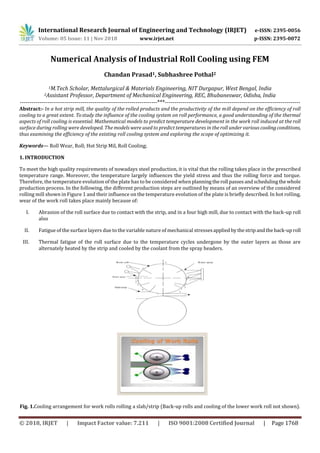
  • 1. International Research Journal of Engineering and Technology (IRJET) e-ISSN: 2395-0056 Volume: 05 Issue: 11 | Nov 2018 www.irjet.net p-ISSN: 2395-0072 © 2018, IRJET | Impact Factor value: 7.211 | ISO 9001:2008 Certified Journal | Page 1768 Numerical Analysis of Industrial Roll Cooling using FEM Chandan Prasad1, Subhashree Pothal2 1M.Tech Scholar, Mettalurgical & Materials Engineering, NIT Durgapur, West Bengal, India 2Assistant Professor, Department of Mechanical Engineering, REC, Bhubaneswar, Odisha, India ----------------------------------------------------------------------***--------------------------------------------------------------------- Abstract:- In a hot strip mill, the quality of the rolled products and the productivity of the mill depend on the efficiency of roll cooling to a great extent. Tostudy the influence of the cooling system on roll performance, a good understanding of the thermal aspects of roll cooling is essential. Mathematical models to predict temperature development in the work roll induced at the roll surface during rolling were developed. The models were used to predict temperatures in the roll under various cooling conditions, thus examining the efficiency of the existing roll cooling system and exploring the scope of optimizing it. Keywords— Roll Wear, Roll; Hot Strip Mil, Roll Cooling; 1. INTRODUCTION To meet the high quality requirements of nowadays steel production, it is vital that the rolling takes place in the prescribed temperature range. Moreover, the temperature largely influences the yield stress and thus the rolling force and torque. Therefore, the temperature evolution of the plate has to be considered when planning theroll passesandschedulingthewhole production process. In the following, the different production steps are outlined by means of an overview of the considered rolling mill shown in Figure 1 and their influence on the temperature evolution of the plate is briefly described. In hot rolling, wear of the work roll takes place mainly because of: I. Abrasion of the roll surface due to contact with the strip, and in a four high mill, due to contact with the back-up roll also II. Fatigue of the surface layers due to the variable nature of mechanical stressesapplied bythestripandtheback-uproll III. Thermal fatigue of the roll surface due to the temperature cycles undergone by the outer layers as those are alternately heated by the strip and cooled by the coolant from the spray headers. Fig. 1.Cooling arrangement for work rolls rolling a slab/strip (Back-up rolls and cooling of the lower work roll not shown).
  • 2. International Research Journal of Engineering and Technology (IRJET) e-ISSN: 2395-0056 Volume: 05 Issue: 11 | Nov 2018 www.irjet.net p-ISSN: 2395-0072 © 2018, IRJET | Impact Factor value: 7.211 | ISO 9001:2008 Certified Journal | Page 1769 When the slab is reheated in a furnace up to 1450K, primary scale grows on the surfaces of the slab, which has to be removed prior to the rolling process because it would otherwise affect the surface quality of the rolled plate. 2. DEVELOPMENT OF THE MATHEMATICAL MODEL OF ROLL TEMPRATURE A typical rollcoolingarrangement is shown in Figure1.Astherollsurfacecomesincontactwiththehotslab/strip,itreceives heat from the slab/strip at a high rate. After the surface comes out of the roll bite, it is subjected to cooling by water sprays. As observed for long and wide strip rolling, the mills often operate near cyclic steady state conditions and the axial heat flow is usually not significant.2)With these assumptions, the equation of heat transfer in the work roll, with respect to a fixed Eulerian reference frame, becomes: Since the work rolls rotate at a high speed, the heat transfer in the circumferential direction by conduction can be neglected compared to the heat transfer by convection (rotation of the rolls). The above equation, then, can be simplified as: Employing the relationship, q =wt, the above equation becomes: .......................(1) Where t is the time taken for an elemental volume of the roll to rotate through an angle q measured from the reference point This equation is subject to the following boundary conditions: (i) At the roll surface, For t>0 and r=R, (t){T-T∞}.......................(2) For h(t) and T∞, the ambient would be different in different zones. For example, in the roll bite, the strip surface is the ambient whereas in the zone where water is impinged on the roll surface, the cooling water is the ambient. (i) As rolling proceeds, the temperature of the roll gradually increases. In a typical rolling operation where the roll is rotated rapidly, if rolling takes place continuously (without any interval between rolling of two consecutive slabs), the major portion inside the roll achieves a nearly steady and uniform temperature after a certain time from the commencement of rolling and temperature variations are localized in a very thin layer near the surface. Therefore,thisthinlayeronlyneeds tobe considered in the model.2) For t>0 and r=R—d ,
  • 3. International Research Journal of Engineering and Technology (IRJET) e-ISSN: 2395-0056 Volume: 05 Issue: 11 | Nov 2018 www.irjet.net p-ISSN: 2395-0072 © 2018, IRJET | Impact Factor value: 7.211 | ISO 9001:2008 Certified Journal | Page 1770 ................................(3) According to Tseng,3)d can be found from the following equation: d =7RPe—1/2 where Pe=w R2/a . ‘d ’ was calculated for the work rolls of Stand No. 1 of the finishing mill of the Tata Steel HSM and was found to be about 7.2 mm.The accuracy of the model depends considerably on the values of the heat transfer coefficients used for different zones. 2.1.1 Roll Bite Zone From the measurements of work roll temperature in a roughing mill, Stevens et. al.1) estimated that the heat transfer coefficient (HTC) within the roll bite (zone 1 in Fig. 1) was 37.6 kW/(m2 K) during the first 30 ms in the arc of contact and 18 kW/(m2 K) thereafter. These values of HTCs were used for the roll bite zone in the present model. To get the strip surface temperature, heat transfer in both the roll and the strip have to be modeled together.However,inthepresentstudy,modelingof strip heat transfer was avoided by assuming strip surface temperature on the basis of plant data and literature. 2.1.2. Water Impingement Zone The work rolls are cooled by spraying water on the roll surface (zones 4 and 6 in Fig. 1). Devadaset al.,4) in their work, determined the heat transfer coefficients in the water impingement zones from Yamaguchi et al.’s correlation 5): q˙sp =(1.11)(1.163)(105)W˙0.521 .................(4) The samecorrelation was used in the present study forthe water impingementzones.Thewaterfluxes(W˙)werecalculated from the spray configuration.The above correlationisbasedonexperimentalmeasurementsofthethermalresponseofaheated plate to spray cooling. The plate temperature was in the range of 100 – 400°C and water fluxes varied from 5 000 to 50 000 L/m2/min. The heat transfer coefficient was obtained from the relationship as follows: q˙sp=h(t)×(Ts—T∞) To get the heat transfer coefficient in this zoneforroll surface temperaturelessthan100°C,therelationshipforheattransfer from a rotating cylinder6) was used as below: h(t)=0.11(0.5Re2+Gr Pr)0.35×k /D ............(5) The values of Rew and GrD can be obtained from the following equations: Rew=pD2w/n and GrD = g b (Ts —T∞ )D3/n2 The properties Pr, ks, n and b at the mean fluid temperature Tf can be used in the above equations, where Tf=(Ts+T∞)/2. 2.1.3. Water Streaming Zone In this zone, the surface of the rolls is covered with a film of water streaming down from the spray zones above. In Fig.1 , these zones have been marked by 3 and 7. The heat transfer coefficient in these zones would depend on the roll surface temperature. For surface temperature less than or equal to the saturation temperature of water (Tsat), the heat transfer coefficient was calculated from Eq. (5). For roll surface temperature above the saturation temperature of water, pool boiling4) heat transfer equations were used as follows: (i) For Tsat<T ŠTmax (temperature of critical heat flux), Rohsenow’s correlation for nucleate boiling was used.
  • 4. International Research Journal of Engineering and Technology (IRJET) e-ISSN: 2395-0056 Volume: 05 Issue: 11 | Nov 2018 www.irjet.net p-ISSN: 2395-0072 © 2018, IRJET | Impact Factor value: 7.211 | ISO 9001:2008 Certified Journal | Page 1771 Fig. 2. Predicted variation of temperature of a point of the roll with time during rolling. 2.1.4. Other Zones For the remaining zones (2, 5 and 8 in Fig. 1), the heat losses from the roll surface were assumed to take place by convection according to Eq. (5) and radiation. Using the implicit technique, finitedifference equations weredeveloped to solve the governing equation ofheattransfer(1) numerically along with boundary conditions (2) and (3). A value of 12 mm was chosen for d .To solve the finite difference equations, a computer programme in C language was written. The grid size and the time step were taken such that further refinement of those did not make any appreciable change in the output. 3. VALIDATION OF THE MODEL Toassess the accuracy of the model, it was employedto reproduce the conditions published byStevens et al.1) foraroughing mill operation. Stevens et al. instrumented a work roll withthermocouples and measuredthetemperatureresponseatdifferent depths below the surface. With the operating conditions for the roughing mill work roll described in Stevens et al.’spaper, the work roll temperaturevariation was predicted with the present model.TheresultsforthefirsttworevolutionsareshowninFig. 2. It can be seen from the figure that the surface of the roll would reach a peak of 545°C during the first revolution and a peak of 565°C during the second revolution. The predictedtemperaturevariationatdifferentdepthsfromtherollsurfacehavealsobeen depicted in the figure. Table 1. Comparison of model predicted work roll tempera tures with published measured data. 4. APPLICATION OF THE MODEL The above model was applied to the upper work roll of Stand No. 1 of the finishing mill of HSM at TATA STEEL with the following inputs: Parameter Value Slab thickness at entry side 33 mm Slab thickness at exit side 18 mm Slab temperature at entry 1040ºC Average slab surface temperature in the bite zone 940ºC Angular speed of the roll 45 rpm Roll diameter 700 mm
  • 5. International Research Journal of Engineering and Technology (IRJET) e-ISSN: 2395-0056 Volume: 05 Issue: 11 | Nov 2018 www.irjet.net p-ISSN: 2395-0072 © 2018, IRJET | Impact Factor value: 7.211 | ISO 9001:2008 Certified Journal | Page 1772 The results discussed below will refer to the above work roll. The figure shows temperatures at the surface as well as at different depths from the surface. It is revealed from the figure that any point on the roll surface during its first working revolution attains a peak temperature of 490°C and subsequently cools down to a minimum temperature of 51°C. During the second revolution, the maximum and minimum temperatures attained by the roll surface are predicted to be 503 and 61°C respectively.The maximum and minimum temperatures attained bythe rollsurfaceduringthesixthrevolutionare,aspredicted by the model, 521 and 80°C respectively. The figure also reveals that at the end of the first working revolution of a point at a depth of 3.5 mm from the surface, the temperaturewouldbe about 49.5°C. The temperatureat this pointoftheroll,attheendof the sixth revolution, would be about 95°C, as predicted by the model. The temperatures at a point of the roll at a depth of 7 mm from the surface would be about 35 and 71°C at the end of the first and sixth revolutions of the point respectively. 5. EFFECT OF LOCATION OF SPRAYING NOZZLES The heat that can be taken out from the roll surface progressively diminishes as the surface movesfurther from the roll bite because the heatconducts towards the core and is not sufficiently availableon the surface for removal.Therefore,coolingofthe work roll by sprays should start as close to the roll bite as possible. The model was utilized to evaluate the influence of the position of the spraying nozzles on cooling of the work roll. All other conditions were taken same as the existing ones with the upper work roll at the 1st stand of the finishing mill. Fig.3.Cooling arrangement (earlier) for work rolls rolling a slab/strip (back-up rolls and cooling of the lower work roll not shown). Earlier, the angular positionof the lower most rowof nozzles at the exit sideof the workroll under study was about 100°,as shown in Fig. 3. A few yearsago, the nozzles wereshifted towards the roll biteto someextent and the new angular positionwas about 65°, as shown in Fig. 1. It was found that the maximum and minimum surface temperatures did not practically change. However, the roll body temperature reduced to some extent from 189 to 184.5°C. The plastic strain/cycle was predicted to reduce from 3.921×10—3 to3.873×10—3. 5.1 Effect of Rate of Cooling Water Flow The model was used to evaluate roll temperatureand the consequent thermal strain for various rates ofcooling water flow, all other conditions remaining same. Presently, the total rate of water flow (upper work roll, 1st stand) is about 317 m3/h. 5.2 Combined Effect of Cooling Water Flow Rate and Number of Rows of Nozzles The model was utilized to examine the effects of changing the number ofrowsofsprayingnozzlesatbothentryandexitsides together with varying the rate of water flow.It was found that if the upper row of nozzles at the entry side was withdrawn and the water flows at all the other rows were unaltered, the maximum surface temperature and the roll body temperature would increase to 556 and 198°C respectively from the present values of 550 and 184.5°C respectively and the plastic strain/cycle at the surface would increase from 3.873×10—3 to 4.337×10—3. The model also revealed that if all the cooling water at the entry side (100 m3/h at present) were delivered through the lower row only, the exit side conditions remaining the same, the maxi- mum surface temperatureand the roll body temperaturewouldincrease to 554 and 194°Crespectivelyfromthepresentvalues of 550 and 184.5°C respectively and the plastic strain/cycle at the surface wouldincrease from 3.873×10—3 to 4.177×10—3.The findings are summarized in Table2.
  • 6. International Research Journal of Engineering and Technology (IRJET) e-ISSN: 2395-0056 Volume: 05 Issue: 11 | Nov 2018 www.irjet.net p-ISSN: 2395-0072 © 2018, IRJET | Impact Factor value: 7.211 | ISO 9001:2008 Certified Journal | Page 1773 Table 2. Effect of roll cooling parameters on roll temperature and thermal strain (No. of rows of nozzles at the entry side = 2). It can be noted here that the mathematical model developed predicts temperatures when roll temperatures havestabilized after a certain time of continuous rolling (without any interval between rolling of two consecutive slabs). This is useful in comparing roll performanceunder variousconditionsandinhavingbasicinformationaboutthemeritsanddemeritsofdifferent cooling systems. Therefore, to evaluate the actual effects of different cooling conditions on roll temperature and the consequent thermal strain, a separatemodel was developed in which, the effect of intermittent rolling was taken into care. Forthis,theentireradius of the work roll had to be considered in the model. It was done by taking the interior boundary condition as follows: For t>0 and r=0 ................................(7) Difference of material properties between high chrom iron(roll shell material)ande.g.iron(corematerial)wereconsidered in the model. It can be mentioned that the heat transfer coefficient at the bite zone would depend on the condition whether the rolls are in the process of rolling any slab or at the stage of idling between rolling of two consecutive slabs. To get the actual situation, the full radius model was applied to the work roll under two different conditions as follows:  Condition A (present condition) No. of rows of nozzles at the entry side: 2 No. of rows of nozzles at the exit side: 3 Total cooling water flow: 317 m3/h  Condition B No. of rows of nozzles at the entry side: 2 No. of rows of nozzles at the exit side: 4 Total cooling water flow: 380 m3/h (20 % more than at present)
  • 7. International Research Journal of Engineering and Technology (IRJET) e-ISSN: 2395-0056 Volume: 05 Issue: 11 | Nov 2018 www.irjet.net p-ISSN: 2395-0072 © 2018, IRJET | Impact Factor value: 7.211 | ISO 9001:2008 Certified Journal | Page 1774 Fig. 4. Roll temperature at different depths from the surface at or nearly at the end of roll bite after 45min. from the start of rolling. Fig. 5. Roll temperature at different depths from the surface at or nearly at the end of roll bite after 90 min. from the start of rolling. Table 3.Roll temperatures at surface and at different depths at different timesfromthe commencementofrollingunderthe present condition Table 3.Roll temperatures at surface and at different depths at different times from the commencement of rolling under the present condition. However, to capture the maximum benefits available with possible modifcation, the following cooling arrangement for the upper work roll of the 1st stand of the finishing mill can be under- taken: No. of rows of spraying nozzles at the entry side: 2 No. of rows of spraying nozzles at the exit side: 4 Rate of cooling water flow 1st (Lower most) row at the exit side: 110 m3/h (same as at present) 2nd row at the exit side: 50 m3/h (same as at present) 3rd row at the exit side: 57 m3/h (same as at present)
  • 8. International Research Journal of Engineering and Technology (IRJET) e-ISSN: 2395-0056 Volume: 05 Issue: 11 | Nov 2018 www.irjet.net p-ISSN: 2395-0072 © 2018, IRJET | Impact Factor value: 7.211 | ISO 9001:2008 Certified Journal | Page 1775 4th (uppermost) row (additional row) at the exit side:44 m3/h Upper row at the entry side: 77 m3/h Lower row at the entry side: 42 m3/h Total flow of cooling water: 380m3/h Location of the exiting rows: Same as at present 5.3 Effect of Strip Lubrication Some lubricants used during rolling havea significant effect on heat transferintherollbite.Thus,striplubricationcanhavea marked effect on roll temperature. C. Devadaset al.4) examined the influence of strip lubricants on work rolltemperaturesusing the data obtained by Murata et al.7) in laboratory experiments. Murata et al. calculated the heat transfer coefficients that would apply to hot rolling under a variety of conditions bymeasuring the thermal response ofa high temperature(780°C)specimenin contact with a low temperature specimen in compression. 6. SUMMARY A computer programme was developed to compute thermal strain induced at the roll surface during rolling. With the above models, roll temperatures and thermal stresses generated at the roll surface during rolling under various cooling conditions can be predicted and thus an optimum cooling system can be arrived at. The above models wereappliedtotheupper work roll of the 1st stand of the finishing mill of HSM at Tata Steel to assess the efficiency of the existing roll coolingsystemand optimize it, if required. The major findings are as follows: 1) The model predicted the amount by which the thermal fatigue oftheroll wouldincreaseifanyrowofsprayingnozzles from the entry or exit sides of the work roll were withdrawn, thus justifying the provision of the existing rows. 2) For the present cooling arrangement, the optimum total water flow may be taken as 350 m3/h, which is 10 % more than the present flow. 3) The model revealed that by increasing the number of rows of nozzles and the water flow rate, it was possible to decrease the plastic strain/cycle in the roll and hence in- crease roll life. However, the increase in roll life over the present one may not be much. 4) Some modification in the existing roll cooling sys- tem was recommended to capture the maximum benefitsavailable with possible modification. 5) There are some lubricants for strip lubrication which can reduce the maximum temperature attained by the roll surface during rolling by a considerable extent. It was found that if 40 % CaCO3 in hot rolling oil was used for lubrication of the strip, the maximum roll temperature would reduce to 407°C from the present 550°C. The model also revealed that if an inorganic salt such as KPO3 were used as a lubricant, the peak roll temperature would de- crease to222°C. REFERENCES 1) P. G. Stevens, K. P. Ivens and P. Harper: J. Iron Steel Inst., (1971), January, 1. 2) A. A. Tseng: Trans. ASME, 106 (1984), 512. 3)A. A. Tseng: Numer. Heat Transfer, 7 (1984),113. 4)C. Devadas and I. V. Samarasekera: Ironmaking Steelmaking, 13, (1986), No. 6, 313. 5)Y. Yamaguchi, M. Nakao, K. Takatsuka, S. Murakami and K.Hirata: 6)Nippon Steel Tech. Rep., 33 (1985), 4. 7)F. Kreith and M. S. Bohn: Principles of Heat Transfer, 4thed., Harper &Row, New York, (1986),266. 8)K. Murata, H. Morise, M. Mitsutsuka, H. Haito, T. Komatsuand S. Shida: Trans. Iron Steel Inst., Jpn.,24(1984),No.9,B309.B. Krishna and A. K. Singh: Proc. of the Seminar on ‘Rolls for Rolling of Flat Products’, The Institution of Engineers(India), Jamshedpur Local Centre, Jamshedpur, (1992), 9