IRJET- Analysis of Heat Transfer in Engine Cylinder Fins for Varying Geometry and Material through Ansys
•
0 likes•38 views

https://irjet.net/archives/V7/i2/IRJET-V7I2103.pdf

Recommended
Recommended
More Related Content
What's hot
What's hot (20)
Similar to IRJET- Analysis of Heat Transfer in Engine Cylinder Fins for Varying Geometry and Material through Ansys
Similar to IRJET- Analysis of Heat Transfer in Engine Cylinder Fins for Varying Geometry and Material through Ansys (20)
More from IRJET Journal
More from IRJET Journal (20)
Recently uploaded
Recently uploaded (20)
IRJET- Analysis of Heat Transfer in Engine Cylinder Fins for Varying Geometry and Material through Ansys
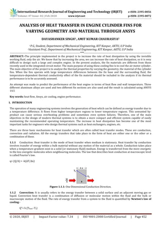
- 1. International Research Journal of Engineering and Technology (IRJET) e-ISSN: 2395-0056 Volume: 07 Issue: 02 | Feb 2020 www.irjet.net p-ISSN: 2395-0072 © 2020, IRJET | Impact Factor value: 7.34 | ISO 9001:2008 Certified Journal | Page 452 ANALYSIS OF HEAT TRANSFER IN ENGINE CYLINDER FINS FOR VARYING GEOMETRY AND MATERIAL THROUGH ANSYS DAYASHANKER SINGH1, AMIT KUMAR CHAURASIYA2 1P.G, Student, Department of Mechanical Engineering, KIT Kanpur, AKTU, U.P India 2Assistant Prof., Department of Mechanical Engineering, KIT Kanpur, AKTU, U.P India --------------------------------------------------------------------------***----------------------------------------------------------------------- ABSTRACT:-The principle implemented in the project is to increase the rate of heat dissipation by using the invisible working fluid, only the air. We know that by increasing the area, we can increase the rate of heat dissipation, so it is very difficult to design such a large and complex engine. In the present analysis, the fin materials are different from those recently used in the integrated circuit motor. The main purpose of using these cooling fins is to cool the air motor cylinder. The main objective of the project is to analyze the thermal properties by varying the geometry, the material of the cylinder fins. When the fins operate with large temperature differences between the fin base and the surrounding fluid, the temperature-dependent thermal conductivity effect of the fin material should be included in the analysis if its thermal performance is to be accurately assessed. An attempt was made to predict the performance of the heat engine in terms of heat flow and wall temperature. Three different aluminum alloys are used and two different fin sections are also used and the result is calculated using ANSYS 14.5 Key words: heat flow, Ansys, air cooling, engine performance. 1. INTRODUCTION The operation of many engineering systems involves the generation of heat which can be defined as energy transfer due to a temperature difference. It flows from higher temperature regions to lower temperature regions. This unwanted by- product can cause serious overheating problems and sometimes even system failures. Therefore, one of the main objectives in the design of modern thermal systems is to obtain a more compact and efficient system capable of easily maintaining the recommended operating temperature. The increase in heat dissipation has become one of the most important tasks for engineers who design thermal systems such as heat exchangers, engines, etc. There are three basic mechanisms for heat transfer which are often called heat transfer modes. These are conduction, convection and radiation. All the energy transfers that take place in the form of heat are either one or the other or a combination of these. 1.1.1 Conduction: Heat transfer is the mode of heat transfer when medium is stationary. Heat transfer by conduction involves transfer of energy within a bulk material without any motion of the material as a whole. Conduction takes place when a temperature gradient exist in a solid (or stationary fluid) medium. Energy is transferred from the more energetic to the less energetic molecules when neighbouring molecules. The law that describes heat conduction at macroscopic level is called Fourier’s law. q= (Q/A) = -k(∆T/∆x) Figure 1.1.1: One Dimensional Conduction Direction. 1.1.2 Convection: It is usually refers to the energy transfer between a solid surface and an adjacent moving gas or liquid. Convection heat transfer is a combination of diffusion or molecular motion within the fluid and the bulk or macroscopic motion of the fluid. The rate of energy transfer from a system to the fluid is quantified by Newton's law of cooling:- Q"= h (Tfluid -Ts)
- 2. International Research Journal of Engineering and Technology (IRJET) e-ISSN: 2395-0056 Volume: 07 Issue: 02 | Feb 2020 www.irjet.net p-ISSN: 2395-0072 © 2020, IRJET | Impact Factor value: 7.34 | ISO 9001:2008 Certified Journal | Page 453 Figure 1.1.2: Convection Heat transfer 1.1.3 Radiation: Heat transfer by radiation can be seen in terms of electromagnetic waves. Any object above 0 K will emit this type of electromagnetic radiation. The best-known example is solar radiation that heats the earth. The total amount of radiation emitted by an object is proportional to the fourth power of the object's temperature, therefore the thermal radiation increases rapidly as the object's temperature increases. This is given by Stefan-Boltzmann's law. 4 Figure 1.1.3: Radiation Heat transfer 1.1.4 An Overview of Fins: Fins are the extended surfaces that are linked to any surface in order to increase the rate of heat transfer from that surface. These are used when the available surface is found inadequate to transfer the required quantity of heat with the available temperature drop and convective heat transfer coefficient. A fin accommodates energy transfer by conduction within its boundaries, while its exposed surfaces transfer energy to the surroundings by convection or radiation or both. Fins are available in many shapes and forms, some of which are shown below: Figure 1.2: some typical examples of extended surfaces (a) longitudinal fin of rectangular profile; (b) cylindrical tube equipped with fins of rectangular profile; (c)longitudinal fin of trapezoidal profile; (d) longitudinal fin of parabolic profile; (e) cylindrical tube equipped with radial fin of rectangular profile; (f) cylindrical tube equipped with radial fin of trapezoidal profile; (g) cylindrical spine; (h) truncated conical spine; (i) truncated parabolic spine. 2. SYSTEM MODEL: Modelling of the model which provides a complete set of design, and manufacturing capabilities. These capabilities include Solid modelling, Surfacing, Rendering, Simulation and NC and tooling design. Since the cooling system of the engine uses air, convection boundary is defined on all the outer surfaces (at fins) of the engine assembly. Modelling is performed by Solid works 2017 software Analysis work performed on ANSYS 14.5. In ANSYS 14.5 we calculate various thermal properties of the material. Thermal properties are calculated by transient thermal analysis, which is the part of ANSYS 14.5
- 3. International Research Journal of Engineering and Technology (IRJET) e-ISSN: 2395-0056 Volume: 07 Issue: 02 | Feb 2020 www.irjet.net p-ISSN: 2395-0072 © 2020, IRJET | Impact Factor value: 7.34 | ISO 9001:2008 Certified Journal | Page 454 Figure 2.1: Engine Cylinder with Circular Fin Engine Cylinder with Triangular Fin The above Solid Works 2017 model is analyzed and solved by ANSYS 14.5 for different types of fins and materials. 3.PROPOSED METHODOLOGY 3.1 Material Specifications Three different materials were selected which are as follows: A380: (Si 7.5-9.5%, Fe 2.0%,Cu 3.0-4.0%,Mn 0.5%,Ni 0.5%,Zn 3.0%,Tin 0.35%, rest is Al) B390-(Si 16-18%,Fe 1.3%,Cu 4-5%,Mg 0.45-0.65%,Mn 0.5%, Ni 1.5%,Ti 0.1%, rest is Al) C443-(Si 4.5 to 6.0%, Fe 0 to 2.0%, Cu 0 to 0.6%, Ni 0 to 0.5%, Zn 0 to 0.5%, Sn 0 to 0.15%, Mg 0 to 0.1%, rest in Al) 3.2 Fins Specification Length of the fin (L) = 130 (mm) = 0.13 (m) Width of the fin (b) = 130 (mm) = 0.13 (m) Thickness (y) = 3 (mm) = 0.003 (m) Thermal Conductivity of fin material = K (W/m × K) Heat transfer coefficient = 0.000025 (W/mm2 × K) or 25 (W/m 2 K) Ref [19] given condition Ta = atmospheric temperature = 295.16 (K) Heat flux= 0.25 (W/ mm2) Some initial values like we give the initial values are convection coefficient h=0.000025 (W/mm2×K), heat flux 0.25 (W/mm2) and ambient temperature is 295.15 (K). For circular design: With the help of Mesh generation tool, after meshing there are 34604 nodes and 17960 elements are made For Triangular Design: With the help of Mesh generation tool, after meshing there are 42157 nodes and 21773 elements are made. Table 3.2: Thermal conductivity of material Sr.No. Aluminum Alloy Thermal conductivity(W/mK) 1 A380 96 2 B390 134 3 C443 140
- 4. International Research Journal of Engineering and Technology (IRJET) e-ISSN: 2395-0056 Volume: 07 Issue: 02 | Feb 2020 www.irjet.net p-ISSN: 2395-0072 © 2020, IRJET | Impact Factor value: 7.34 | ISO 9001:2008 Certified Journal | Page 455 3.3 Circular fin of Al alloy (A380) Figure 3.3.1: Circular fin of Al alloy (A380) Figure 3.3.2: Mesh generated body of Circular Fin of Al alloy (A380) Model is prepared by Slid Works2017, after this use of Add-ins we directly import the model from Solid Works 2017. In ANSYS 14.5 we give the material property to the model. Figure 3.3.3: given load on Circular fin Al alloy A(380)
- 5. International Research Journal of Engineering and Technology (IRJET) e-ISSN: 2395-0056 Volume: 07 Issue: 02 | Feb 2020 www.irjet.net p-ISSN: 2395-0072 © 2020, IRJET | Impact Factor value: 7.34 | ISO 9001:2008 Certified Journal | Page 456 Temperature distribution in Circular fin Al alloy A(380) Temperature distribution of circular fin of Al alloy shows that maximum value of temperature is 428.21K and minimum temperature is 326.29K Figure 3.3.4: Heat flux distribution in Circular fin Al alloy A(380) Figure shows that the heat flux inside Circular fin of Al alloys have maximum value 0.25774 (W/mm2). 3.4 Triangular fin of Al Alloy (A380) Figure 3.4.1: Temperature distribution in Triangular fin of Al Alloy (A380) Temperature distribution of Triangular fin of Al Alloy shows that maximum value of temperature is 475.62 K and minimum temperature is 305.73 K. Figure 3.4.2: Total heat flux inside Triangular fin of Al Alloy (A380) Figure shows that the heat flux inside Triangular fin of Al Alloy have maximum value 0.33025 (W/mm2).
- 6. International Research Journal of Engineering and Technology (IRJET) e-ISSN: 2395-0056 Volume: 07 Issue: 02 | Feb 2020 www.irjet.net p-ISSN: 2395-0072 © 2020, IRJET | Impact Factor value: 7.34 | ISO 9001:2008 Certified Journal | Page 457 3.5 Circular fin of Al alloy (B390) Figure 3.5.1: Temperature distribution in Circular fin of Al alloy (B390) Temperature distribution of Circular fin of Al alloy shows that maximum value of temperature is 401.69K and minimum temperature is 348.31K. Figure 3.5.2: Total heat flux inside Circular fin of Al alloy (B390) Figure shows that the maximum value of heat flux is 0.25756 (W/mm2) inside the circular fin of Al alloy. 3.6 Triangular fin of Al alloy (B390) Figure 3.6.1: Temperature distribution of Triangular fin of Al alloy (B390) Temperature distribution of Triangular fin of Al alloy (B390) shows that maximum value of temperature is 456.14K and minimum temperature is 331.38K.
- 7. International Research Journal of Engineering and Technology (IRJET) e-ISSN: 2395-0056 Volume: 07 Issue: 02 | Feb 2020 www.irjet.net p-ISSN: 2395-0072 © 2020, IRJET | Impact Factor value: 7.34 | ISO 9001:2008 Certified Journal | Page 458 Figure 3.6.2: Total heat flux inside Triangular fin of Al alloy (B390) Figure shows that the maximum value of heat flux is 0.39463 (W/mm2) inside the Triangular fin of Al alloy 3.7 Circular fin of Al alloy (C443) Figure 3.7.1: Temperature distribution of Circular fin of Al alloy (C443) Temperature distribution of Circular fin of Mg alloy shows that maximum value of temperature is 407.17 K and minimum temperature is 353.6 K. Figure 3.7.2: Total heat flux inside Circular fin of Al alloy (C443) Figure shows that the maximum heat flux value 0.25623 (W/mm2) for Circular fin of Al alloy
- 8. International Research Journal of Engineering and Technology (IRJET) e-ISSN: 2395-0056 Volume: 07 Issue: 02 | Feb 2020 www.irjet.net p-ISSN: 2395-0072 © 2020, IRJET | Impact Factor value: 7.34 | ISO 9001:2008 Certified Journal | Page 459 3.8 Triangular fin Al alloy (C443) Figure 3.8.1: Temperature distribution of Triangular fin of Al alloy (C443) Temperature Distribution of Triangular fin of Al alloy shows that maximum value of temperature is 465.09 K and minimum temperature is 337.05 K. Figure 3.8.2: Total Heat flux inside Triangular fin of Al alloy (C443) Figure shows that the maximum value of heat flux is 0.401 (W/mm2) inside the Triangular fin of Al alloy 4.CONCLUSION: In present work, a cylinder fin body is modeled with the help of Solid Works 2017 software and transient thermal analysis is done by using ANSYS 14.5. These fins are used for air cooling systems for two wheelers. In present study, three alloy of Aluminum (A380, B390 and C443) are used and compared with G. Babu and M. LavaKumar results. The various parameters (i.e., shape and geometry of the fin) are considered in the study, shape (Circular and Triangular), and thickness (3 mm) by changing the shape of the fin to triangular shaped, the weight of the fin body reduces thereby increasing the heat transfer rate and efficiency of the fin. Simulation/Experimental Results Table 4.1: Comparison of data Sr. No G. Babu and Lava Kumar Present result Al alloy 2024 Al alloy 6061 A380 B390 C443 Circular 0.723258 0.73814 0.25774 0.25756 0.25623
- 9. International Research Journal of Engineering and Technology (IRJET) e-ISSN: 2395-0056 Volume: 07 Issue: 02 | Feb 2020 www.irjet.net p-ISSN: 2395-0072 © 2020, IRJET | Impact Factor value: 7.34 | ISO 9001:2008 Certified Journal | Page 460 5.FUTURE SCOPES: In this thesis, we concluded that using triangular fins is better, but circular fins are mostly used in vertical engines than horizontal engines and also by using that, the weight of the fin body is also increases. By using triangular fins, the fin body weight is less, so more experiments are to be done to use triangular fins for the fin body in future. REFERENCES: [1] Biermann, A. E. and B. Pinkel (1934). Heat Transfer from finned metal cylinders in an air stream, NACA Report No.488 [2] J. C. Sanders, et al. (1942). Cooling test of an air- cooled engine cylinder with copper fins on the barrel, NACA Report E-103 [3] Denpong Soodphakdee, et al. (2001). "A Comparison of Fin Geometries for Heat sinks in Laminar Forced Convection Part 1 - Round, Elliptical, and Plate Fins in Staggered and In-Line Configurations." The International Journal of Microcircuits and Electronic Packaging 24(1). [4] Fernando Illan and M. Alarcon (2002). "Optimization of Annular Cylindrical and Spherical Fins in an Internal Combustion Engine under Realistic Conditions." Journal of Thermal Science and Engineering Applications 2. [5] A. Bassam and K. A. Hijleh (2003). "Enhanced Forced Convection Heat Transfer from a Cylinder Using Permeable Fins." ASME Journal of Heat Transfer 125. [6] Yoshida Masao, et al. (2005). "Air-Cooling Effects of Fins on a Motorcycle Engine." Nippon Kikai Gakkai Ronbunshu B Hen (Transactions of the Japan Society of Mechanical Engineers Part B) (Japan) 17(9): 2324- 2330. [7] C. Han-Taw and C. Jui- Che (2006). "Investigation of natural convection heat transfer coefficient on a vertical square fin of finned-tube heat exchangers." International Journal of Heat and Mass Transfer 49(17- 18): 3034-3044. [8] A. Mohammadi, et al. (2008). "Analysis of local convective heat transfer in a spark ignition engine." International Communications in Heat and Mass Transfer 35. BIOGRAPHIES DAYASHANKER SINGH P.G Student, Department of Mechanical Engineering, KIT Kanpur, AKTU, U.P India. AMIT KUMAR CHAURASIYA Assistant Prof., Department of Mechanical Engineering, KIT Kanpur, AKTU, U.P India.