SlideShare a Scribd company logo
1 of 5
Download to read offline
International Research Journal of Engineering and Technology (IRJET) e-ISSN: 2395-0056
Volume: 09 Issue: 06 | Jun 2022 www.irjet.net p-ISSN: 2395-0072
© 2022, IRJET | Impact Factor value: 7.529 | ISO 9001:2008 Certified Journal | Page 3256
Sensorless Speed Control of Brushless DC Motor by MATLAB
Vinithaasri. S1, D. Sri Vidhya2
1M. E. Power Systems Engineering, K. S. Rangasamy College of Technology, Tiruchengode, Tamil Nadu - 637 215,
India.
2Associate Professor /EEE, K. S. Rangasamy College of Technology,Tiruchengode, Tamil Nadu - 637 215, India.
---------------------------------------------------------------------***---------------------------------------------------------------------
Abstract - Sensorless BLDC motors are widely used in
household appliances, vehicles, aircraft, consumerelectronics,
medical devices, automated industrial equipment, and
instrumentation. Because of their design, these motors are
employed in a variety of industrial areas. Sensorless BLDC
motors are popular due to their increased efficiency,
reliability, power, acoustic noise, smaller size, lighter weight,
greater dynamic response, enhanced speed vs load torque,
wider speed range, and extended life. It offers a number of
advantages, including the elimination of the motor's neutral
voltage, a predetermined phase shift network, a low starting
speed, and a low cost. This study use MATLAB SIMULINK to
give a straightforward and dependable method for detecting
reverse emf zero-crossings for sensorless operation. An
abstract summarizes, in one paragraph (usually), the major
aspects of the entire paper in the following prescribed
sequence. The zero crossings of the reverse emf are projected
obliquely from the terminal voltages that are monitored in
relation to the dc negative pole, and thus approach never
involves any integration. Furthermore, when using line
voltages, neutral potential and common mode noise are no
longer needed. Through simulation, the efficiency of the
control strategy based on zero-crossing detection from
terminal voltage differences was studied.
Key Words: Sensorless operation, Zero Crossing
Detector, Reverse EMF,Speed control method,Brushless
DC Motor
1. INTRODUCTION
It has several advantages, including the eliminationofmotor
neutral voltage, a set phase shift circuit, a low beginning
speed, and inexpensive cost. Instead of brushes, this BLDC
motor is commutated electronically using power switches.
The voltage surges are caused by the remaining currentthat
is restricted when power switches produce armature
current. In the condition of sensorless BLDC motor driving,
commutation torque ripple has already been reduced.
Analysis, design, and implementation of a high-performance
sensorless method for BLDC motors are completed. BLDC
motors also referred to as PermanentMagnetDirectCurrent
Synchronous motors are still one of the motor types that
have grown in popularity in recent years, owing to their
superior features and performance. The BLDC motor, which
lacks position and speed sensors, has received a lot of
interest. Square wave control and sinusoidal currentcontrol
are the two most common BLDC motor control techniques.
To calculate the zero-crossing time of the reverse emf,
multiply the terminal voltage of the floating winding by the
motor's neutral point. Integration begins when the reverse
emf crosses zero and ends when the given threshold valueis
reached, resulting in immediate commutation. Frequency-
independent phase shifter for sensorless BLDC motor
control, capable of shifting the zero-crossing point of the
input signal with a defined phase delay. Jung and Ha have
developed an extended Kalman filter estimator for a
brushless dc motor to estimatespeedandrotorposition. The
rotor position is obtained indirectly by sensing the reverse
emf from one among the three motor terminal voltages of a
three-phase motor. The necessity to establish the right
values for the covariance matrix parameters, which
represent the errors in modeling and measurements, is a
barrier to using the extended Kalman filter technique for
rotor position estimation. Sensorless control techniques
based on the reverse emf's Zero Cross Point(ZCP)havebeen
widely employed in low-cost applications.Thezero-crossing
detector (ZCD) detects the ZCP of the reverse emf, and the
pulse is created by moving 30° fromtheZCP.WhentheBLDC
motor is at rest or at zero speed, the reverse emf cannot be
calculated using the ZCP technique.
As a result, a unique control is required for the smooth and
dependable sensorless control operation of BLDC motors.
Furthermore, the intricacies of sensorless motor starting
were not discussed. However, the direct commutation
instant detection approach suggested lacks the flexibility to
advance the commutation instant, which may be
implemented utilizing reverse emf zero-crossing detection
techniques. By measuring the motor terminal voltages, we
devised and constructed an integrated circuit enabling the
sensorless operation of a BLDC motor. Frequency
independent phase shifter for sensorless BLDC motor
control, capable of shifting the zero-crossing point of the
input signal with a defined phase delay. For speed and rotor
position estimation, an extended Kalman filter estimatorfor
a brushless dc motor has been created. commutationinstant
boosts torque generation, especially in high-speed BLDC
motor operating. The technique of zero-crossing detection
was utilized to start the BLDC machine successfully in
sensorless mode. The concept is developed in this paper to
present a simple running mode algorithm. In this paper, we
present a simple and reliable approach for detecting reverse
emf zero-crossings in sensorless operation using
MATLAB/SIMULINK, as well as hardware implementation
using DSP. DSP is required in hardware circuits to generate
International Research Journal of Engineering and Technology (IRJET) e-ISSN: 2395-0056
Volume: 09 Issue: 06 | Jun 2022 www.irjet.net p-ISSN: 2395-0072
© 2022, IRJET | Impact Factor value: 7.529 | ISO 9001:2008 Certified Journal | Page 3257
the right moment for pulse production.Thezerocrossingsof
the reverse emf are approximated indirectly from the
terminal voltages measured concerning the dc negative
terminal, and no integration is required. Moreover, when
line voltages are employed, neutral potential and common
mode noise are no longer required. Along with this BLDC
motor model, the dynamic behavior of the motor, including
no-load, load, and load transients,hasbeeninvestigated.The
efficiency of the sensorlesscontrol detectionandlocalization
of zero-crossing via terminal voltage differences has been
studied using simulation.
1.1 Period of Normal Conduction
The terminal voltage waveform is substantially identical to
the reverse-EMF waveform. The terminal voltages, rather
than the reverse-EMFs, can be employed to detect the
commutation points of the BLDC motor in the proposed
sensorless control. As the rotor speed increases, so does the
phase lag's percentage contribution to the entire period. The
latency will disrupt the current alignment with the reverse-
EMF, causing major issues with high-speedcomputation.The
phase lag in commutation can induce substantial pulsing
torques in such drives, which can cause rotor speed
oscillations and excessive copper losses. The cut-off
frequency of the LPF is establishedat 2.5 kHz in thisresearch
by taking into account both the phase lag and the harmonic
dispersion of the reverse-EMF. The hysteresis comparator is
used to correct for the phase lag of the reverse-EMFs caused
by the LPF to establish the optimal inverter commutation
sequence based on rotor position. Furthermore, high-
frequency ripples in the terminal voltages can avoid
numerous output transitions.
1.2 Period of commutation
The traditional start-upprocedureshowscertainunforeseen
limitations that may affect the BLDC motor's performance.
To circumvent these constraints, a simple start-upapproach
is given that not only achieves the highest starting motor
torque but also controls the stator current. Unlike the usual
technique, which only excites two stator windings, the
suggested start-up scheme excites all triostatorwindings by
employing a specified starting voltage vector. The voltage
vector V3 is orthogonal to Vi and is positioned between
voltage vectors V1 and V2. It is selected as the next applied
voltage vector to maximize starting motor torque during
startup. It should be noticed that by varying the pulse width
of the switching devices, the amplitude of the stator current
for alignment of the rotor position may be simply modified.
Shows the three-phase current responsesoftheBLDCmotor
when the switch is turned on and the pulse widthsofthetwo
switches B- and C- are modulated at the same time. PWM
signal duty cycles when the switching period Ts is 100 μ
seconds. The size of the stator current can be readily
controlled by modifying the duty cycle, which can be
determined by taking the initial torque required at
alignment into account. According to the rotor position
before alignment, the motor may revolve in reverse during
alignment. However, because themaximumreverserotation
angle is just 90 mechanical degrees, it does not affect fuel
pump operation. After the rotor position has been aligned,
the start-up method is considered for accelerating the BLDC
motor from a standstill to a certainspeed,3000rpm,whichis
a minimum speed for the automobile fuel pump application.
Because the sensorless scheme does not start on itsown, the
motor must be started and brought to a particular speed
where the zero-crossing position of the reverse-EMFmaybe
detected.
2. Objective
The paper is to develop a sensorless brushless DC (BLDC)
motor control system. Sensorless techniques based on a
hysteresis comparison and apossible start-upmethodwitha
high beginning torque are proposed. The hysteresis
comparator compensates for the phase delay of the reverse
EMFs caused by alow-pass filter (LPF) while also preventing
numerousoutputtransitionscausedbynoiseorfluctuationin
the terminal voltages. The rotorpositionismaintainedatrest
for the greatest starting torque without the need for an extra
sensor or any motor parameter information.
3. Proposed System
The proposed system consists of the voltagesourceinverter
receiving the direct current voltage. The voltage source
inverter is a three-phase voltage source inverter with a 120
degree mode of operation. It comprises three legs, each of
which contains two MOSFETs. In all, six MOSFETs are
employed in the voltage source inverter.MOSFETsareMetal
Oxide Semiconductor Field Effect Transistors. It is the
voltage control device's switching device. If we adjust the
Vgs (Gate Source Voltage), we get a sinusoidal pulse with
modulation signals. We can regulate the Vds (Drain Source
Voltage), which is the output voltage. Induced via changing
modulation. It is defined as the ratio of the reference signal
voltage to the carried signal voltage. In my application, the
reference signal is a three-phase sinusoidal signal with a
displacement of 120 degree and the carrier signal is a
triangular signal. The inverterwill supplypowertotheBLDC
motor by adjusting the modulation.
International Research Journal of Engineering and Technology (IRJET) e-ISSN: 2395-0056
Volume: 09 Issue: 06 | Jun 2022 www.irjet.net p-ISSN: 2395-0072
© 2022, IRJET | Impact Factor value: 7.529 | ISO 9001:2008 Certified Journal | Page 3258
Fig -1: Block diagram of the sensorless brushless
dc motor
As a result of Faraday's law, reverse emf will be induced in
the stator winding. As a result, this return emf will be in the
opposite direction as the source voltage. So, if we can detect
this reverse emf, we can feed it into the hysteresis
comparator. However, the reverse emf form is trapezoidal
because of the motor's salient pole rotor. We can't readily
distinguish "0" and "1" in this trapezoidal reverse emf. As a
result, the reverse emf provided to the LPF will beconverted
from trapezoidal to sinusoidal. This is passed on to the
hysteresis comparator. The hysteresis comparator is the
difference between the upper and lower values. It is an
alternating current motor with a stator similar to a three-
phase induction motor. The rotor is comprised of a
permanent magnet with four poles (projected Pole) It lacks
rotor winding, mechanical commutator, and brushes, yet its
speed-torque constant is similar to that of a DC shunt motor.
This is referred to as a BLDC motor. To provide power to the
motor stator winding, an electronic commutator (voltage
source) inverter is employed.
4. SENSORLESS BLDC MOTOR SIMULATION
The voltage source inverter receives the input DC voltage
and converts it to AC voltage. To generate the reverse emf, a
sinusoidal V/F control PWM approachisappliedtotheBLDC
motor, causing the motor to start asaninductionmotor.This
emf is detected using a voltage sensor, and the voltage is
passed to the hysteresis comparator. The hysteresis
comparator determines which winding should be energized
first; this comparator compares the EMFs of two phases and
generates PWM pulses; these pulses are fed to the inverter,
and the inverter supplies voltage to the motor; however, the
voltage sensor produces trapezoidal reverse emf, and when
this trapezoidal reverse emf is fed to the low pass filter, it
produces sinusoidal reverse emf. The hysteresis current
controller compares the actual motorcurrentandreferences
current waveforms; the difference is output as PWM pulses
by the current controller. The voltage source inverter
receives this pulse.
Fig -2: Simulation of Sensorless BLDC Motor
Table -1: Sample Table format
Parameters
Motor rating 1.5Hp
Rated torque 2.5N-m
Type of motor BLDC Motor
Supply voltage 420V
Rated speed 4630rpm
Rated current 5A
The inverter will supply voltage to the motor, reducing
stator current. Sensorless control is achieved by the use of a
hysteresis comparator approach, which includes LPFs for
suppressing high switching frequency ripples, hysteresis
comparators for creating three-phase commutation signals,
and a gating signals generator for generating six Pulses.
When detecting the three-phase terminal voltages, each one
is fed into an LPF to reduce the high switching frequency
fluctuation or noise. Because the BLDC motor only has two
phases activated at any given moment,theback-EMFmaybe
determined from its terminal voltage in the duration of an
open phase (60°). The only variation between the reverse-
EMF and its terminal voltage throughout the two-phase
conduction period (120°) is a statorimpedancevoltagedrop,
which may be negligible when compared to the DC voltage
source. The sensorless method inverter will supply voltage
to the motor, reducing stator current. Sensorless control is
achieved by the use of a hysteresis comparator approach,
which includes LPFs for suppressing high switching
frequency ripples,hysteresiscomparatorsforcreatingthree-
phase commutation signals, and a gating signals generator
for generating six Pulses. When detecting the three-phase
terminal voltages, each one is fed into an LPF to reduce the
high switching frequency fluctuation or noise. Because the
BLDC motor only has two phases activated at any given
moment, the back-EMF may be determinedfromitsterminal
International Research Journal of Engineering and Technology (IRJET) e-ISSN: 2395-0056
Volume: 09 Issue: 06 | Jun 2022 www.irjet.net p-ISSN: 2395-0072
© 2022, IRJET | Impact Factor value: 7.529 | ISO 9001:2008 Certified Journal | Page 3259
voltage in the duration of an open phase (60°). The only
variation between the reverse-EMF and its terminal voltage
throughout the two-phase conduction period (120°) is a
stator impedance voltage drop, which may be negligible
when compared to the DC voltage source. The sensorless
method is simulated in MATLAB/SIMULINK in fig. 2.
5. Results and Discussion
In the proposed system, the simulated
graph of BLDC current and Back Emf shows that initially
the motor start from negative value of -2A and after
steadily attains its peak current of 2.5A for the time of
0.005s. The total amplitude of the current is 5A and its
time period for 1 cycle is 0.02 seconds. In the BLDC Back
EMF, amplitude of the Back EMF is 100v for the time
period of 0.005s and 0.02s for full cycle has shown in the
fig.3.
Fig -3: BLDC Current and reverse EMF
In the motor speed waveform, the initial speed of BLDC
motor is 500 rpm at time t = 0 and the final speed is rated
to 2000 rpm at time t=4.25s has shown in fig.4.
Fig -4: Motor Speed
In the torque waveform, the initial minimum value is -
38.7205 N-m and the maximum value is 40.27 N-m. The
constant peak value of torque is 2.5 N-m and minimum
constant value is 1.32 N-m has shown in fig. 5.
Fig -2 Torque Waveform
From the rotor angle waveform, the rotor angle starts rising
from the time of 3s and it gets reached upto 1777.75 at the
time of 10s has shown in fig.8.
Fig -5: Rotor Angle Waveform
From the PWM pulse generator, the gate pulse if value 1
starts generated after the time period of 3s in fig.6.
Fig -6: Gate Pulse Waveform
The dc voltage is 283.329v at initially and it gets peak value
of 500v. A constant voltage is 214.5 after the time period of
4..3s has shown in fig.7.
International Research Journal of Engineering and Technology (IRJET) e-ISSN: 2395-0056
Volume: 09 Issue: 06 | Jun 2022 www.irjet.net p-ISSN: 2395-0072
© 2022, IRJET | Impact Factor value: 7.529 | ISO 9001:2008 Certified Journal | Page 3260
Fig -7: DC Link Voltage
The voltage is compared by hysteresis comparator block
and their waveforms are shown in fig. 8 and 9.
Fig -8: Hysteresis Comparator 1
Fig -9: Hysteresis Comparator 2
5. Conclusion
This paper proposes a sensorlesscontrol basedona terminal
voltage hysteresis comparator and a potential start-up
approach with a high starting torque. By changing both the
resistance ratio and the output voltagelevel ofthehysteresis
comparator, the maximum commutation phase lag is
lowered from -13° to 3°. The commutation signal is almost
parallel to the back-EMF. High-frequency fluctuations in the
terminal voltage can prevent numerousoutputtransitionsat
a hysteresis comparator. The stator current ripples were
decreased by using the hysteresis current controller. The PI
controller is used to accomplish closed-loop speed control.
REFERENCES
[1] Bharathi Sankar A and Dr.Seyezhai R (2014),
“Sensorless Control of BLDC Motor using Back EMF-
based Detection Method”., IJEE, Vol.-No.6, Issue No.02.
[2] Carlson R and Milchel L. M (1992), “Analysis of torque
ripple due to phase commutation in brushless dc
machines”, IEEE Trans. Ind. Appl., Vol. 28, No. 3, pp.
632–638
[3] Kim D.K and Lee K.W (2006), “Commutation torque
ripple reduction in a position sensorless brushless dc
motor drive”, IEEE Trans. Power Electron.,Vol.21,No.6,
pp. 1762–1768.
[4] Liu Y and Howe D (2007), “Commutation torque ripple
minimization in direct-torque-controlled PM brushless
dc drives”, IEEE Trans. Ind. Electron., Vol. 43, No. 4, pp.
1012–1021.
[5] Merin John and Vinu Thomas (2014), “Position
Sensorless Control of BLDC motor based on Back EMF
difference estimation method”, IEEE.
[6] Saranya R, Saravan Kumar S. and Baskaran. R (2014),
“Sensorless Operation Brushless DC Motor Driveusing
Back EMF Technique”, Vol -No-3, Issue No -4 PP; 255-
257., IJER.
[7] Son Y.C, Jang K.Y. and Suh B.S (2008), “Integrated
MOSFET inverter module of low-power drive system”,
IEEE Trans. Ind. Appl., Vol. 44, No. 3, pp. 878–886
[8] Tae-Won Chun, Quang-Vinth and Hong-Hee Lee (2014),
“Sensorless Control of BLDC Motor Drive for an
Automotive Fuel Pump Using a HysteresisComparator”,
IEEE, Vol-29, No.3.
[9] Xia C and Li L (2009), “A control strategy forfour-switch
three-phase brushless dc motor using single current
sensor”, IEEE Trans. Ind. Electron., Vol. 56, No. 6, pp.
2058–2066.
[10] Zhang L and Qu W.L (2008), “A new torque control
method for torque ripple minimization of BLDC motor
with un-ideal back EMF”, IEEE Trans. Power Electron.,
Vol. 23, No. 2, pp. 950–958.

More Related Content

Similar to Sensorless Speed Control of Brushless DC Motor by MATLAB

Speed Control of PMBLDC Motor using LPC 2148 – A Practical Approach
Speed Control of PMBLDC Motor using  LPC 2148 – A Practical Approach  Speed Control of PMBLDC Motor using  LPC 2148 – A Practical Approach
Speed Control of PMBLDC Motor using LPC 2148 – A Practical Approach
IJEEE
 
torque Ripple Minimization of BLDC Motor
torque Ripple Minimization of BLDC Motortorque Ripple Minimization of BLDC Motor
torque Ripple Minimization of BLDC Motor
PoojaBan
 
235420144 analysis-and-control-of-four-quadrant-operation-of-three-phase-brus...
235420144 analysis-and-control-of-four-quadrant-operation-of-three-phase-brus...235420144 analysis-and-control-of-four-quadrant-operation-of-three-phase-brus...
235420144 analysis-and-control-of-four-quadrant-operation-of-three-phase-brus...
Ankit Agrawal
 

Similar to Sensorless Speed Control of Brushless DC Motor by MATLAB (20)

Embedded based sensorless control of pmbldc motor with voltage controlled pfc...
Embedded based sensorless control of pmbldc motor with voltage controlled pfc...Embedded based sensorless control of pmbldc motor with voltage controlled pfc...
Embedded based sensorless control of pmbldc motor with voltage controlled pfc...
 
IRJET- A Review on - PMBLDC Motor Drive with Power Factor Correction Controller
IRJET- A Review on - PMBLDC Motor Drive with Power Factor Correction ControllerIRJET- A Review on - PMBLDC Motor Drive with Power Factor Correction Controller
IRJET- A Review on - PMBLDC Motor Drive with Power Factor Correction Controller
 
IRJET - Three-Phase Single Switch PWM Controlled Induction Motor Drive
IRJET - Three-Phase Single Switch PWM Controlled Induction Motor DriveIRJET - Three-Phase Single Switch PWM Controlled Induction Motor Drive
IRJET - Three-Phase Single Switch PWM Controlled Induction Motor Drive
 
C010511620
C010511620C010511620
C010511620
 
IJSRED-V2I3P85
IJSRED-V2I3P85IJSRED-V2I3P85
IJSRED-V2I3P85
 
Comparitive Analysis of Speed and Position Control of BLDC Motor via Field Or...
Comparitive Analysis of Speed and Position Control of BLDC Motor via Field Or...Comparitive Analysis of Speed and Position Control of BLDC Motor via Field Or...
Comparitive Analysis of Speed and Position Control of BLDC Motor via Field Or...
 
Speed Control of PMBLDC Motor using LPC 2148 – A Practical Approach
Speed Control of PMBLDC Motor using  LPC 2148 – A Practical Approach  Speed Control of PMBLDC Motor using  LPC 2148 – A Practical Approach
Speed Control of PMBLDC Motor using LPC 2148 – A Practical Approach
 
Da33612620
Da33612620Da33612620
Da33612620
 
Da33612620
Da33612620Da33612620
Da33612620
 
Predefined speed control of bldc motor
Predefined speed control of bldc motorPredefined speed control of bldc motor
Predefined speed control of bldc motor
 
IRJET- Analysis the Speed Manage of BLDC Motor Drive using Sensors
IRJET- Analysis the Speed Manage of BLDC Motor Drive using SensorsIRJET- Analysis the Speed Manage of BLDC Motor Drive using Sensors
IRJET- Analysis the Speed Manage of BLDC Motor Drive using Sensors
 
torque Ripple Minimization of BLDC Motor
torque Ripple Minimization of BLDC Motortorque Ripple Minimization of BLDC Motor
torque Ripple Minimization of BLDC Motor
 
235420144 analysis-and-control-of-four-quadrant-operation-of-three-phase-brus...
235420144 analysis-and-control-of-four-quadrant-operation-of-three-phase-brus...235420144 analysis-and-control-of-four-quadrant-operation-of-three-phase-brus...
235420144 analysis-and-control-of-four-quadrant-operation-of-three-phase-brus...
 
Analysis and control of four quadrant operation of three phase brushless dc (...
Analysis and control of four quadrant operation of three phase brushless dc (...Analysis and control of four quadrant operation of three phase brushless dc (...
Analysis and control of four quadrant operation of three phase brushless dc (...
 
E010213442
E010213442E010213442
E010213442
 
IRJET- Comparative Study of Sensor and Sensor Less Control of Three Phase...
IRJET-  	  Comparative Study of Sensor and Sensor Less Control of Three Phase...IRJET-  	  Comparative Study of Sensor and Sensor Less Control of Three Phase...
IRJET- Comparative Study of Sensor and Sensor Less Control of Three Phase...
 
Power Quality Analysis of Vienna Rectifier for BLDC Motor Drive Application
Power Quality Analysis of Vienna Rectifier for BLDC Motor Drive ApplicationPower Quality Analysis of Vienna Rectifier for BLDC Motor Drive Application
Power Quality Analysis of Vienna Rectifier for BLDC Motor Drive Application
 
Speed Torque Characteristics of BLDC Motor with Load Variations
Speed Torque Characteristics of BLDC Motor with Load VariationsSpeed Torque Characteristics of BLDC Motor with Load Variations
Speed Torque Characteristics of BLDC Motor with Load Variations
 
Aw35271276
Aw35271276Aw35271276
Aw35271276
 
IRJET- Variable Frequency Drive Used in Treadmill
IRJET- Variable Frequency Drive Used in TreadmillIRJET- Variable Frequency Drive Used in Treadmill
IRJET- Variable Frequency Drive Used in Treadmill
 

More from IRJET Journal

More from IRJET Journal (20)

TUNNELING IN HIMALAYAS WITH NATM METHOD: A SPECIAL REFERENCES TO SUNGAL TUNNE...
TUNNELING IN HIMALAYAS WITH NATM METHOD: A SPECIAL REFERENCES TO SUNGAL TUNNE...TUNNELING IN HIMALAYAS WITH NATM METHOD: A SPECIAL REFERENCES TO SUNGAL TUNNE...
TUNNELING IN HIMALAYAS WITH NATM METHOD: A SPECIAL REFERENCES TO SUNGAL TUNNE...
 
STUDY THE EFFECT OF RESPONSE REDUCTION FACTOR ON RC FRAMED STRUCTURE
STUDY THE EFFECT OF RESPONSE REDUCTION FACTOR ON RC FRAMED STRUCTURESTUDY THE EFFECT OF RESPONSE REDUCTION FACTOR ON RC FRAMED STRUCTURE
STUDY THE EFFECT OF RESPONSE REDUCTION FACTOR ON RC FRAMED STRUCTURE
 
A COMPARATIVE ANALYSIS OF RCC ELEMENT OF SLAB WITH STARK STEEL (HYSD STEEL) A...
A COMPARATIVE ANALYSIS OF RCC ELEMENT OF SLAB WITH STARK STEEL (HYSD STEEL) A...A COMPARATIVE ANALYSIS OF RCC ELEMENT OF SLAB WITH STARK STEEL (HYSD STEEL) A...
A COMPARATIVE ANALYSIS OF RCC ELEMENT OF SLAB WITH STARK STEEL (HYSD STEEL) A...
 
Effect of Camber and Angles of Attack on Airfoil Characteristics
Effect of Camber and Angles of Attack on Airfoil CharacteristicsEffect of Camber and Angles of Attack on Airfoil Characteristics
Effect of Camber and Angles of Attack on Airfoil Characteristics
 
A Review on the Progress and Challenges of Aluminum-Based Metal Matrix Compos...
A Review on the Progress and Challenges of Aluminum-Based Metal Matrix Compos...A Review on the Progress and Challenges of Aluminum-Based Metal Matrix Compos...
A Review on the Progress and Challenges of Aluminum-Based Metal Matrix Compos...
 
Dynamic Urban Transit Optimization: A Graph Neural Network Approach for Real-...
Dynamic Urban Transit Optimization: A Graph Neural Network Approach for Real-...Dynamic Urban Transit Optimization: A Graph Neural Network Approach for Real-...
Dynamic Urban Transit Optimization: A Graph Neural Network Approach for Real-...
 
Structural Analysis and Design of Multi-Storey Symmetric and Asymmetric Shape...
Structural Analysis and Design of Multi-Storey Symmetric and Asymmetric Shape...Structural Analysis and Design of Multi-Storey Symmetric and Asymmetric Shape...
Structural Analysis and Design of Multi-Storey Symmetric and Asymmetric Shape...
 
A Review of “Seismic Response of RC Structures Having Plan and Vertical Irreg...
A Review of “Seismic Response of RC Structures Having Plan and Vertical Irreg...A Review of “Seismic Response of RC Structures Having Plan and Vertical Irreg...
A Review of “Seismic Response of RC Structures Having Plan and Vertical Irreg...
 
A REVIEW ON MACHINE LEARNING IN ADAS
A REVIEW ON MACHINE LEARNING IN ADASA REVIEW ON MACHINE LEARNING IN ADAS
A REVIEW ON MACHINE LEARNING IN ADAS
 
Long Term Trend Analysis of Precipitation and Temperature for Asosa district,...
Long Term Trend Analysis of Precipitation and Temperature for Asosa district,...Long Term Trend Analysis of Precipitation and Temperature for Asosa district,...
Long Term Trend Analysis of Precipitation and Temperature for Asosa district,...
 
P.E.B. Framed Structure Design and Analysis Using STAAD Pro
P.E.B. Framed Structure Design and Analysis Using STAAD ProP.E.B. Framed Structure Design and Analysis Using STAAD Pro
P.E.B. Framed Structure Design and Analysis Using STAAD Pro
 
A Review on Innovative Fiber Integration for Enhanced Reinforcement of Concre...
A Review on Innovative Fiber Integration for Enhanced Reinforcement of Concre...A Review on Innovative Fiber Integration for Enhanced Reinforcement of Concre...
A Review on Innovative Fiber Integration for Enhanced Reinforcement of Concre...
 
Survey Paper on Cloud-Based Secured Healthcare System
Survey Paper on Cloud-Based Secured Healthcare SystemSurvey Paper on Cloud-Based Secured Healthcare System
Survey Paper on Cloud-Based Secured Healthcare System
 
Review on studies and research on widening of existing concrete bridges
Review on studies and research on widening of existing concrete bridgesReview on studies and research on widening of existing concrete bridges
Review on studies and research on widening of existing concrete bridges
 
React based fullstack edtech web application
React based fullstack edtech web applicationReact based fullstack edtech web application
React based fullstack edtech web application
 
A Comprehensive Review of Integrating IoT and Blockchain Technologies in the ...
A Comprehensive Review of Integrating IoT and Blockchain Technologies in the ...A Comprehensive Review of Integrating IoT and Blockchain Technologies in the ...
A Comprehensive Review of Integrating IoT and Blockchain Technologies in the ...
 
A REVIEW ON THE PERFORMANCE OF COCONUT FIBRE REINFORCED CONCRETE.
A REVIEW ON THE PERFORMANCE OF COCONUT FIBRE REINFORCED CONCRETE.A REVIEW ON THE PERFORMANCE OF COCONUT FIBRE REINFORCED CONCRETE.
A REVIEW ON THE PERFORMANCE OF COCONUT FIBRE REINFORCED CONCRETE.
 
Optimizing Business Management Process Workflows: The Dynamic Influence of Mi...
Optimizing Business Management Process Workflows: The Dynamic Influence of Mi...Optimizing Business Management Process Workflows: The Dynamic Influence of Mi...
Optimizing Business Management Process Workflows: The Dynamic Influence of Mi...
 
Multistoried and Multi Bay Steel Building Frame by using Seismic Design
Multistoried and Multi Bay Steel Building Frame by using Seismic DesignMultistoried and Multi Bay Steel Building Frame by using Seismic Design
Multistoried and Multi Bay Steel Building Frame by using Seismic Design
 
Cost Optimization of Construction Using Plastic Waste as a Sustainable Constr...
Cost Optimization of Construction Using Plastic Waste as a Sustainable Constr...Cost Optimization of Construction Using Plastic Waste as a Sustainable Constr...
Cost Optimization of Construction Using Plastic Waste as a Sustainable Constr...
 

Recently uploaded

result management system report for college project
result management system report for college projectresult management system report for college project
result management system report for college project
Tonystark477637
 
Call for Papers - African Journal of Biological Sciences, E-ISSN: 2663-2187, ...
Call for Papers - African Journal of Biological Sciences, E-ISSN: 2663-2187, ...Call for Papers - African Journal of Biological Sciences, E-ISSN: 2663-2187, ...
Call for Papers - African Journal of Biological Sciences, E-ISSN: 2663-2187, ...
Christo Ananth
 
Call for Papers - Educational Administration: Theory and Practice, E-ISSN: 21...
Call for Papers - Educational Administration: Theory and Practice, E-ISSN: 21...Call for Papers - Educational Administration: Theory and Practice, E-ISSN: 21...
Call for Papers - Educational Administration: Theory and Practice, E-ISSN: 21...
Christo Ananth
 

Recently uploaded (20)

The Most Attractive Pune Call Girls Budhwar Peth 8250192130 Will You Miss Thi...
The Most Attractive Pune Call Girls Budhwar Peth 8250192130 Will You Miss Thi...The Most Attractive Pune Call Girls Budhwar Peth 8250192130 Will You Miss Thi...
The Most Attractive Pune Call Girls Budhwar Peth 8250192130 Will You Miss Thi...
 
Introduction and different types of Ethernet.pptx
Introduction and different types of Ethernet.pptxIntroduction and different types of Ethernet.pptx
Introduction and different types of Ethernet.pptx
 
MANUFACTURING PROCESS-II UNIT-1 THEORY OF METAL CUTTING
MANUFACTURING PROCESS-II UNIT-1 THEORY OF METAL CUTTINGMANUFACTURING PROCESS-II UNIT-1 THEORY OF METAL CUTTING
MANUFACTURING PROCESS-II UNIT-1 THEORY OF METAL CUTTING
 
UNIT - IV - Air Compressors and its Performance
UNIT - IV - Air Compressors and its PerformanceUNIT - IV - Air Compressors and its Performance
UNIT - IV - Air Compressors and its Performance
 
Porous Ceramics seminar and technical writing
Porous Ceramics seminar and technical writingPorous Ceramics seminar and technical writing
Porous Ceramics seminar and technical writing
 
DJARUM4D - SLOT GACOR ONLINE | SLOT DEMO ONLINE
DJARUM4D - SLOT GACOR ONLINE | SLOT DEMO ONLINEDJARUM4D - SLOT GACOR ONLINE | SLOT DEMO ONLINE
DJARUM4D - SLOT GACOR ONLINE | SLOT DEMO ONLINE
 
result management system report for college project
result management system report for college projectresult management system report for college project
result management system report for college project
 
(SHREYA) Chakan Call Girls Just Call 7001035870 [ Cash on Delivery ] Pune Esc...
(SHREYA) Chakan Call Girls Just Call 7001035870 [ Cash on Delivery ] Pune Esc...(SHREYA) Chakan Call Girls Just Call 7001035870 [ Cash on Delivery ] Pune Esc...
(SHREYA) Chakan Call Girls Just Call 7001035870 [ Cash on Delivery ] Pune Esc...
 
Russian Call Girls in Nagpur Grishma Call 7001035870 Meet With Nagpur Escorts
Russian Call Girls in Nagpur Grishma Call 7001035870 Meet With Nagpur EscortsRussian Call Girls in Nagpur Grishma Call 7001035870 Meet With Nagpur Escorts
Russian Call Girls in Nagpur Grishma Call 7001035870 Meet With Nagpur Escorts
 
Call Girls Pimpri Chinchwad Call Me 7737669865 Budget Friendly No Advance Boo...
Call Girls Pimpri Chinchwad Call Me 7737669865 Budget Friendly No Advance Boo...Call Girls Pimpri Chinchwad Call Me 7737669865 Budget Friendly No Advance Boo...
Call Girls Pimpri Chinchwad Call Me 7737669865 Budget Friendly No Advance Boo...
 
Roadmap to Membership of RICS - Pathways and Routes
Roadmap to Membership of RICS - Pathways and RoutesRoadmap to Membership of RICS - Pathways and Routes
Roadmap to Membership of RICS - Pathways and Routes
 
Call for Papers - African Journal of Biological Sciences, E-ISSN: 2663-2187, ...
Call for Papers - African Journal of Biological Sciences, E-ISSN: 2663-2187, ...Call for Papers - African Journal of Biological Sciences, E-ISSN: 2663-2187, ...
Call for Papers - African Journal of Biological Sciences, E-ISSN: 2663-2187, ...
 
Introduction to Multiple Access Protocol.pptx
Introduction to Multiple Access Protocol.pptxIntroduction to Multiple Access Protocol.pptx
Introduction to Multiple Access Protocol.pptx
 
Call for Papers - Educational Administration: Theory and Practice, E-ISSN: 21...
Call for Papers - Educational Administration: Theory and Practice, E-ISSN: 21...Call for Papers - Educational Administration: Theory and Practice, E-ISSN: 21...
Call for Papers - Educational Administration: Theory and Practice, E-ISSN: 21...
 
CCS335 _ Neural Networks and Deep Learning Laboratory_Lab Complete Record
CCS335 _ Neural Networks and Deep Learning Laboratory_Lab Complete RecordCCS335 _ Neural Networks and Deep Learning Laboratory_Lab Complete Record
CCS335 _ Neural Networks and Deep Learning Laboratory_Lab Complete Record
 
ONLINE FOOD ORDER SYSTEM PROJECT REPORT.pdf
ONLINE FOOD ORDER SYSTEM PROJECT REPORT.pdfONLINE FOOD ORDER SYSTEM PROJECT REPORT.pdf
ONLINE FOOD ORDER SYSTEM PROJECT REPORT.pdf
 
Water Industry Process Automation & Control Monthly - April 2024
Water Industry Process Automation & Control Monthly - April 2024Water Industry Process Automation & Control Monthly - April 2024
Water Industry Process Automation & Control Monthly - April 2024
 
Online banking management system project.pdf
Online banking management system project.pdfOnline banking management system project.pdf
Online banking management system project.pdf
 
Extrusion Processes and Their Limitations
Extrusion Processes and Their LimitationsExtrusion Processes and Their Limitations
Extrusion Processes and Their Limitations
 
Booking open Available Pune Call Girls Koregaon Park 6297143586 Call Hot Ind...
Booking open Available Pune Call Girls Koregaon Park  6297143586 Call Hot Ind...Booking open Available Pune Call Girls Koregaon Park  6297143586 Call Hot Ind...
Booking open Available Pune Call Girls Koregaon Park 6297143586 Call Hot Ind...
 

Sensorless Speed Control of Brushless DC Motor by MATLAB

  • 1. International Research Journal of Engineering and Technology (IRJET) e-ISSN: 2395-0056 Volume: 09 Issue: 06 | Jun 2022 www.irjet.net p-ISSN: 2395-0072 © 2022, IRJET | Impact Factor value: 7.529 | ISO 9001:2008 Certified Journal | Page 3256 Sensorless Speed Control of Brushless DC Motor by MATLAB Vinithaasri. S1, D. Sri Vidhya2 1M. E. Power Systems Engineering, K. S. Rangasamy College of Technology, Tiruchengode, Tamil Nadu - 637 215, India. 2Associate Professor /EEE, K. S. Rangasamy College of Technology,Tiruchengode, Tamil Nadu - 637 215, India. ---------------------------------------------------------------------***--------------------------------------------------------------------- Abstract - Sensorless BLDC motors are widely used in household appliances, vehicles, aircraft, consumerelectronics, medical devices, automated industrial equipment, and instrumentation. Because of their design, these motors are employed in a variety of industrial areas. Sensorless BLDC motors are popular due to their increased efficiency, reliability, power, acoustic noise, smaller size, lighter weight, greater dynamic response, enhanced speed vs load torque, wider speed range, and extended life. It offers a number of advantages, including the elimination of the motor's neutral voltage, a predetermined phase shift network, a low starting speed, and a low cost. This study use MATLAB SIMULINK to give a straightforward and dependable method for detecting reverse emf zero-crossings for sensorless operation. An abstract summarizes, in one paragraph (usually), the major aspects of the entire paper in the following prescribed sequence. The zero crossings of the reverse emf are projected obliquely from the terminal voltages that are monitored in relation to the dc negative pole, and thus approach never involves any integration. Furthermore, when using line voltages, neutral potential and common mode noise are no longer needed. Through simulation, the efficiency of the control strategy based on zero-crossing detection from terminal voltage differences was studied. Key Words: Sensorless operation, Zero Crossing Detector, Reverse EMF,Speed control method,Brushless DC Motor 1. INTRODUCTION It has several advantages, including the eliminationofmotor neutral voltage, a set phase shift circuit, a low beginning speed, and inexpensive cost. Instead of brushes, this BLDC motor is commutated electronically using power switches. The voltage surges are caused by the remaining currentthat is restricted when power switches produce armature current. In the condition of sensorless BLDC motor driving, commutation torque ripple has already been reduced. Analysis, design, and implementation of a high-performance sensorless method for BLDC motors are completed. BLDC motors also referred to as PermanentMagnetDirectCurrent Synchronous motors are still one of the motor types that have grown in popularity in recent years, owing to their superior features and performance. The BLDC motor, which lacks position and speed sensors, has received a lot of interest. Square wave control and sinusoidal currentcontrol are the two most common BLDC motor control techniques. To calculate the zero-crossing time of the reverse emf, multiply the terminal voltage of the floating winding by the motor's neutral point. Integration begins when the reverse emf crosses zero and ends when the given threshold valueis reached, resulting in immediate commutation. Frequency- independent phase shifter for sensorless BLDC motor control, capable of shifting the zero-crossing point of the input signal with a defined phase delay. Jung and Ha have developed an extended Kalman filter estimator for a brushless dc motor to estimatespeedandrotorposition. The rotor position is obtained indirectly by sensing the reverse emf from one among the three motor terminal voltages of a three-phase motor. The necessity to establish the right values for the covariance matrix parameters, which represent the errors in modeling and measurements, is a barrier to using the extended Kalman filter technique for rotor position estimation. Sensorless control techniques based on the reverse emf's Zero Cross Point(ZCP)havebeen widely employed in low-cost applications.Thezero-crossing detector (ZCD) detects the ZCP of the reverse emf, and the pulse is created by moving 30° fromtheZCP.WhentheBLDC motor is at rest or at zero speed, the reverse emf cannot be calculated using the ZCP technique. As a result, a unique control is required for the smooth and dependable sensorless control operation of BLDC motors. Furthermore, the intricacies of sensorless motor starting were not discussed. However, the direct commutation instant detection approach suggested lacks the flexibility to advance the commutation instant, which may be implemented utilizing reverse emf zero-crossing detection techniques. By measuring the motor terminal voltages, we devised and constructed an integrated circuit enabling the sensorless operation of a BLDC motor. Frequency independent phase shifter for sensorless BLDC motor control, capable of shifting the zero-crossing point of the input signal with a defined phase delay. For speed and rotor position estimation, an extended Kalman filter estimatorfor a brushless dc motor has been created. commutationinstant boosts torque generation, especially in high-speed BLDC motor operating. The technique of zero-crossing detection was utilized to start the BLDC machine successfully in sensorless mode. The concept is developed in this paper to present a simple running mode algorithm. In this paper, we present a simple and reliable approach for detecting reverse emf zero-crossings in sensorless operation using MATLAB/SIMULINK, as well as hardware implementation using DSP. DSP is required in hardware circuits to generate
  • 2. International Research Journal of Engineering and Technology (IRJET) e-ISSN: 2395-0056 Volume: 09 Issue: 06 | Jun 2022 www.irjet.net p-ISSN: 2395-0072 © 2022, IRJET | Impact Factor value: 7.529 | ISO 9001:2008 Certified Journal | Page 3257 the right moment for pulse production.Thezerocrossingsof the reverse emf are approximated indirectly from the terminal voltages measured concerning the dc negative terminal, and no integration is required. Moreover, when line voltages are employed, neutral potential and common mode noise are no longer required. Along with this BLDC motor model, the dynamic behavior of the motor, including no-load, load, and load transients,hasbeeninvestigated.The efficiency of the sensorlesscontrol detectionandlocalization of zero-crossing via terminal voltage differences has been studied using simulation. 1.1 Period of Normal Conduction The terminal voltage waveform is substantially identical to the reverse-EMF waveform. The terminal voltages, rather than the reverse-EMFs, can be employed to detect the commutation points of the BLDC motor in the proposed sensorless control. As the rotor speed increases, so does the phase lag's percentage contribution to the entire period. The latency will disrupt the current alignment with the reverse- EMF, causing major issues with high-speedcomputation.The phase lag in commutation can induce substantial pulsing torques in such drives, which can cause rotor speed oscillations and excessive copper losses. The cut-off frequency of the LPF is establishedat 2.5 kHz in thisresearch by taking into account both the phase lag and the harmonic dispersion of the reverse-EMF. The hysteresis comparator is used to correct for the phase lag of the reverse-EMFs caused by the LPF to establish the optimal inverter commutation sequence based on rotor position. Furthermore, high- frequency ripples in the terminal voltages can avoid numerous output transitions. 1.2 Period of commutation The traditional start-upprocedureshowscertainunforeseen limitations that may affect the BLDC motor's performance. To circumvent these constraints, a simple start-upapproach is given that not only achieves the highest starting motor torque but also controls the stator current. Unlike the usual technique, which only excites two stator windings, the suggested start-up scheme excites all triostatorwindings by employing a specified starting voltage vector. The voltage vector V3 is orthogonal to Vi and is positioned between voltage vectors V1 and V2. It is selected as the next applied voltage vector to maximize starting motor torque during startup. It should be noticed that by varying the pulse width of the switching devices, the amplitude of the stator current for alignment of the rotor position may be simply modified. Shows the three-phase current responsesoftheBLDCmotor when the switch is turned on and the pulse widthsofthetwo switches B- and C- are modulated at the same time. PWM signal duty cycles when the switching period Ts is 100 μ seconds. The size of the stator current can be readily controlled by modifying the duty cycle, which can be determined by taking the initial torque required at alignment into account. According to the rotor position before alignment, the motor may revolve in reverse during alignment. However, because themaximumreverserotation angle is just 90 mechanical degrees, it does not affect fuel pump operation. After the rotor position has been aligned, the start-up method is considered for accelerating the BLDC motor from a standstill to a certainspeed,3000rpm,whichis a minimum speed for the automobile fuel pump application. Because the sensorless scheme does not start on itsown, the motor must be started and brought to a particular speed where the zero-crossing position of the reverse-EMFmaybe detected. 2. Objective The paper is to develop a sensorless brushless DC (BLDC) motor control system. Sensorless techniques based on a hysteresis comparison and apossible start-upmethodwitha high beginning torque are proposed. The hysteresis comparator compensates for the phase delay of the reverse EMFs caused by alow-pass filter (LPF) while also preventing numerousoutputtransitionscausedbynoiseorfluctuationin the terminal voltages. The rotorpositionismaintainedatrest for the greatest starting torque without the need for an extra sensor or any motor parameter information. 3. Proposed System The proposed system consists of the voltagesourceinverter receiving the direct current voltage. The voltage source inverter is a three-phase voltage source inverter with a 120 degree mode of operation. It comprises three legs, each of which contains two MOSFETs. In all, six MOSFETs are employed in the voltage source inverter.MOSFETsareMetal Oxide Semiconductor Field Effect Transistors. It is the voltage control device's switching device. If we adjust the Vgs (Gate Source Voltage), we get a sinusoidal pulse with modulation signals. We can regulate the Vds (Drain Source Voltage), which is the output voltage. Induced via changing modulation. It is defined as the ratio of the reference signal voltage to the carried signal voltage. In my application, the reference signal is a three-phase sinusoidal signal with a displacement of 120 degree and the carrier signal is a triangular signal. The inverterwill supplypowertotheBLDC motor by adjusting the modulation.
  • 3. International Research Journal of Engineering and Technology (IRJET) e-ISSN: 2395-0056 Volume: 09 Issue: 06 | Jun 2022 www.irjet.net p-ISSN: 2395-0072 © 2022, IRJET | Impact Factor value: 7.529 | ISO 9001:2008 Certified Journal | Page 3258 Fig -1: Block diagram of the sensorless brushless dc motor As a result of Faraday's law, reverse emf will be induced in the stator winding. As a result, this return emf will be in the opposite direction as the source voltage. So, if we can detect this reverse emf, we can feed it into the hysteresis comparator. However, the reverse emf form is trapezoidal because of the motor's salient pole rotor. We can't readily distinguish "0" and "1" in this trapezoidal reverse emf. As a result, the reverse emf provided to the LPF will beconverted from trapezoidal to sinusoidal. This is passed on to the hysteresis comparator. The hysteresis comparator is the difference between the upper and lower values. It is an alternating current motor with a stator similar to a three- phase induction motor. The rotor is comprised of a permanent magnet with four poles (projected Pole) It lacks rotor winding, mechanical commutator, and brushes, yet its speed-torque constant is similar to that of a DC shunt motor. This is referred to as a BLDC motor. To provide power to the motor stator winding, an electronic commutator (voltage source) inverter is employed. 4. SENSORLESS BLDC MOTOR SIMULATION The voltage source inverter receives the input DC voltage and converts it to AC voltage. To generate the reverse emf, a sinusoidal V/F control PWM approachisappliedtotheBLDC motor, causing the motor to start asaninductionmotor.This emf is detected using a voltage sensor, and the voltage is passed to the hysteresis comparator. The hysteresis comparator determines which winding should be energized first; this comparator compares the EMFs of two phases and generates PWM pulses; these pulses are fed to the inverter, and the inverter supplies voltage to the motor; however, the voltage sensor produces trapezoidal reverse emf, and when this trapezoidal reverse emf is fed to the low pass filter, it produces sinusoidal reverse emf. The hysteresis current controller compares the actual motorcurrentandreferences current waveforms; the difference is output as PWM pulses by the current controller. The voltage source inverter receives this pulse. Fig -2: Simulation of Sensorless BLDC Motor Table -1: Sample Table format Parameters Motor rating 1.5Hp Rated torque 2.5N-m Type of motor BLDC Motor Supply voltage 420V Rated speed 4630rpm Rated current 5A The inverter will supply voltage to the motor, reducing stator current. Sensorless control is achieved by the use of a hysteresis comparator approach, which includes LPFs for suppressing high switching frequency ripples, hysteresis comparators for creating three-phase commutation signals, and a gating signals generator for generating six Pulses. When detecting the three-phase terminal voltages, each one is fed into an LPF to reduce the high switching frequency fluctuation or noise. Because the BLDC motor only has two phases activated at any given moment,theback-EMFmaybe determined from its terminal voltage in the duration of an open phase (60°). The only variation between the reverse- EMF and its terminal voltage throughout the two-phase conduction period (120°) is a statorimpedancevoltagedrop, which may be negligible when compared to the DC voltage source. The sensorless method inverter will supply voltage to the motor, reducing stator current. Sensorless control is achieved by the use of a hysteresis comparator approach, which includes LPFs for suppressing high switching frequency ripples,hysteresiscomparatorsforcreatingthree- phase commutation signals, and a gating signals generator for generating six Pulses. When detecting the three-phase terminal voltages, each one is fed into an LPF to reduce the high switching frequency fluctuation or noise. Because the BLDC motor only has two phases activated at any given moment, the back-EMF may be determinedfromitsterminal
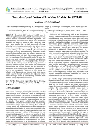
  • 4. International Research Journal of Engineering and Technology (IRJET) e-ISSN: 2395-0056 Volume: 09 Issue: 06 | Jun 2022 www.irjet.net p-ISSN: 2395-0072 © 2022, IRJET | Impact Factor value: 7.529 | ISO 9001:2008 Certified Journal | Page 3259 voltage in the duration of an open phase (60°). The only variation between the reverse-EMF and its terminal voltage throughout the two-phase conduction period (120°) is a stator impedance voltage drop, which may be negligible when compared to the DC voltage source. The sensorless method is simulated in MATLAB/SIMULINK in fig. 2. 5. Results and Discussion In the proposed system, the simulated graph of BLDC current and Back Emf shows that initially the motor start from negative value of -2A and after steadily attains its peak current of 2.5A for the time of 0.005s. The total amplitude of the current is 5A and its time period for 1 cycle is 0.02 seconds. In the BLDC Back EMF, amplitude of the Back EMF is 100v for the time period of 0.005s and 0.02s for full cycle has shown in the fig.3. Fig -3: BLDC Current and reverse EMF In the motor speed waveform, the initial speed of BLDC motor is 500 rpm at time t = 0 and the final speed is rated to 2000 rpm at time t=4.25s has shown in fig.4. Fig -4: Motor Speed In the torque waveform, the initial minimum value is - 38.7205 N-m and the maximum value is 40.27 N-m. The constant peak value of torque is 2.5 N-m and minimum constant value is 1.32 N-m has shown in fig. 5. Fig -2 Torque Waveform From the rotor angle waveform, the rotor angle starts rising from the time of 3s and it gets reached upto 1777.75 at the time of 10s has shown in fig.8. Fig -5: Rotor Angle Waveform From the PWM pulse generator, the gate pulse if value 1 starts generated after the time period of 3s in fig.6. Fig -6: Gate Pulse Waveform The dc voltage is 283.329v at initially and it gets peak value of 500v. A constant voltage is 214.5 after the time period of 4..3s has shown in fig.7.
  • 5. International Research Journal of Engineering and Technology (IRJET) e-ISSN: 2395-0056 Volume: 09 Issue: 06 | Jun 2022 www.irjet.net p-ISSN: 2395-0072 © 2022, IRJET | Impact Factor value: 7.529 | ISO 9001:2008 Certified Journal | Page 3260 Fig -7: DC Link Voltage The voltage is compared by hysteresis comparator block and their waveforms are shown in fig. 8 and 9. Fig -8: Hysteresis Comparator 1 Fig -9: Hysteresis Comparator 2 5. Conclusion This paper proposes a sensorlesscontrol basedona terminal voltage hysteresis comparator and a potential start-up approach with a high starting torque. By changing both the resistance ratio and the output voltagelevel ofthehysteresis comparator, the maximum commutation phase lag is lowered from -13° to 3°. The commutation signal is almost parallel to the back-EMF. High-frequency fluctuations in the terminal voltage can prevent numerousoutputtransitionsat a hysteresis comparator. The stator current ripples were decreased by using the hysteresis current controller. The PI controller is used to accomplish closed-loop speed control. REFERENCES [1] Bharathi Sankar A and Dr.Seyezhai R (2014), “Sensorless Control of BLDC Motor using Back EMF- based Detection Method”., IJEE, Vol.-No.6, Issue No.02. [2] Carlson R and Milchel L. M (1992), “Analysis of torque ripple due to phase commutation in brushless dc machines”, IEEE Trans. Ind. Appl., Vol. 28, No. 3, pp. 632–638 [3] Kim D.K and Lee K.W (2006), “Commutation torque ripple reduction in a position sensorless brushless dc motor drive”, IEEE Trans. Power Electron.,Vol.21,No.6, pp. 1762–1768. [4] Liu Y and Howe D (2007), “Commutation torque ripple minimization in direct-torque-controlled PM brushless dc drives”, IEEE Trans. Ind. Electron., Vol. 43, No. 4, pp. 1012–1021. [5] Merin John and Vinu Thomas (2014), “Position Sensorless Control of BLDC motor based on Back EMF difference estimation method”, IEEE. [6] Saranya R, Saravan Kumar S. and Baskaran. R (2014), “Sensorless Operation Brushless DC Motor Driveusing Back EMF Technique”, Vol -No-3, Issue No -4 PP; 255- 257., IJER. [7] Son Y.C, Jang K.Y. and Suh B.S (2008), “Integrated MOSFET inverter module of low-power drive system”, IEEE Trans. Ind. Appl., Vol. 44, No. 3, pp. 878–886 [8] Tae-Won Chun, Quang-Vinth and Hong-Hee Lee (2014), “Sensorless Control of BLDC Motor Drive for an Automotive Fuel Pump Using a HysteresisComparator”, IEEE, Vol-29, No.3. [9] Xia C and Li L (2009), “A control strategy forfour-switch three-phase brushless dc motor using single current sensor”, IEEE Trans. Ind. Electron., Vol. 56, No. 6, pp. 2058–2066. [10] Zhang L and Qu W.L (2008), “A new torque control method for torque ripple minimization of BLDC motor with un-ideal back EMF”, IEEE Trans. Power Electron., Vol. 23, No. 2, pp. 950–958.