Downloaded 12 times
![Int. Journal of Electrical & Electronics Engg. Vol. 2, Spl. Issue 1 (2015) e-ISSN: 1694-2310 | p-ISSN: 1694-2426
NITTTR, Chandigarh EDIT -2015 128
Speed Control of PMBLDC Motor using
LPC 2148 – A Practical Approach
G.A.Rathy1, P.Sivasankar2
1
Assistant Professor, Electrical Department, NITTTR, Chennai, India.
2
Assistant Professor, Electronics Department, NITTTR, Chennai, India.
rathysanju@gmail.com, siva_sankar123p@yahoo.com
ABSTRACT: Permanent Magnet Brushless DC Motor
(PMBLDC) motors are gaining popularity in industries like
automotive, aircrafts, medical Appliances, electric traction,
disk drive, industrial drives and instrumentation because of
their high efficiency, silent operation, high power factor,
reliability, compact, low maintenance and high torque to
power ratio. The PMBLDC motor requires an inverter and a
position sensor that exposes rotor position for appropriate
alternation of current. The control in the inverter circuit is
achieved using LPC 2148.The pulses generated by LPC 2148
controls the power devices of the inverter circuit. The rotation
of the PMBLDC motor is built on the feedback of rotor
position that is gained from the hall sensors. PMBLDC motor
generally utilizes three hall sensors for deciding the
commutation sequence. In this paper it is proposed to achieve
a practical effective speed control of PMBLDC motor using
LPC 2148.
Keywords: PMBLDC Motor, Speed Control, PWM, Duty cycle, hall
sensors
1. INTRODUCTION
DC motors have a high starting torque. DC motors were
preferred and are still often used for adjustable speed
applications. The disadvantages of Brush Type DC Motors
are the brushes. These brushes have to be inspected from
time to time and replaced when they are worn out. So,
brush DC motors have a limited life and often its life
cannot easily be predicted. The windings of the DC motor
are on the armature. For rapid start-stop applications the
inertia of the heavy armature can be a major drawback. To
overcome these drawbacks the construction of the DC
motors were altered and this resulted in the Permanent
Magnet Brushless DC motor. Brushless DC (BLDC)
motors are rapidly gaining popularity. They offer longer
life and less maintenance than conventional brushed DC
motors [3]. Some other advantages over brushed DC
motors and induction motors are:
Better speed versus torque characteristics
Faster dynamic response
High efficiency
Long operating life
Noiseless operation
Higher speed range.
And in addition, the ratio of torque delivered to the size of
the motor is higher, making them useful in applications
where space and weight are critical factors [4].
2. LITERATURE SURVEY
Ravikiran et al in [1] represented the modeling of the
Permanent Magnet Brushless DC (PMBLDC) motor drive
using Matlab / Simulink Software. The modelling of
Permanent Magnet Brushless DC (PMBLDC) motor drive
is useful in various phenomenons such as aerospace
modelling and more other applications. In that Paper, the
modelling of PMBLDC motor drive is done by using
various components such as current, Speed controllers and
sensors are installed to sense the various factors such as
speed, current, and the output obtained from the inverter.
The basic purpose of designing of such drive is to gives the
certain ideas about designing of the motor drive using
Matlab / Simulink [1] and how it helps in various
applications such as electric Traction, automotive
industries and more other places. Prakash et al.in [2],
proposed the model for Closed Loop Controlled Buck
Converter Fed PMBLDC Drive System using Simulation.
Vandana Govindan et al in [5] presented digital speed
control of permanent magnet brushless dc motor using
TMS320F2812 DSP controller . The DSP controller used
here has the special features for digital motor control.
Control algorithms used for the speed control has been
implemented by assembly language programming in
TMS320F2812 DSP controller. According to the input
command, feedback and the control algorithm, the PWM
pulses for each phase is generated by the DSP and is given
to the MOSFET driver. The output of the driver is 6
independent PWM pulses that have to be given to the
corresponding gates of the six MOSFETs
power switches used in the three-phase bridge inverter
whose output is given to the stator of the Brushless DC
Motor. The complete system model is simulated in
MATLAB/ Simulink environment. Hardware
implementation for the speed control has been achieved by
programming in the DSP controller TMS320F2812 [5].
But in this paper, the speed control of PMBLDC motor is
achieved using LPC 2148 microcontroller. This LPC2148
is very simple compared to TMS320F2812 DSP processor.
Also writing programs to generate the PWM is much easier
than DSP based system control. Also in our proposed
model we experimentally control the speed of the
PMBLDC motor instead of using any simulation.
3. CONSTRUCTION OF PMBLDC MOTOR
In this section, the construction of PMBLDC motor will be
discussed.
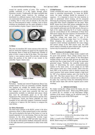
3.1 Stator
Brushless DC motor Stator has Silicon steel stampings
with slots in its interior surface. These slots accommodate
a closed distributed armature windings. These windings are](https://image.slidesharecdn.com/id86-150525205124-lva1-app6891/85/Speed-Control-of-PMBLDC-Motor-using-LPC-2148-A-Practical-Approach-1-320.jpg)
![Int. Journal of Electrical & Electronics Engg. Vol. 2, Spl. Issue 1 (2015) e-ISSN: 1694-2310 | p-ISSN: 1694-2426
131 NITTTR, Chandigarh EDIT-2015
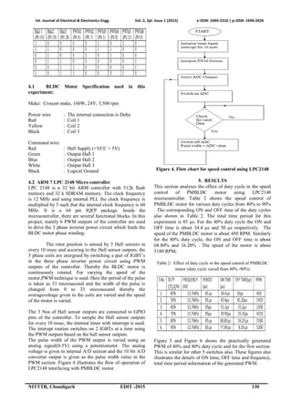
Figure 5. PWM1 40% duty cycle
Figure 6. PWM1 80% duty cycle
6. CONCLUSION
This paper has proposed a practical approach to achieve an
efficient speed control of PMBLDC motor using LPC-
2148 micro controller. For various PWM such as 40% to
90% variation of duty cycle, the speed of the PMBLDC
motor is efficiently controlled. This practical approach of
speed control using LPC2148 is an efficient method
compared to other speed control methods.
REFERENCES
[1] Ravikiran H. Rushiya, Renish M. George, Prateek R. Dongre, Swapnil
B. Borkar, Shankar S. Soneker And S. W. Khubalkar, “A Review:
Modelling of Permanent Magnet Brushless DC Motor Drive”,
International Journal of Application or Innovation in Engineering &
Management (IJAIEM), 2013.
[2] S. Prakash , R. Dhanasekaran , Syed Ammal,, “Modelling and
Simulation of Closed Loop Controlled Buck Converter Fed PMBLDC
Drive System”, Research Journal of Applied Sciences, Engineering
and Technology 3(4): 284-289, ISSN: 2040-7467, 2011.
[3] R. Somanatham , P. V. N. Prasad , A. D. Rajkumar, “Simulation of
PMBLDC Motor With Sinusoidal Excitation Using Trapezoidal
Control Strategy”, (ICIEA 2006) 0-7803-9514-X/06, 2006.
[4] Padmaraja Yedamale, “Brushless DC (BLDC) Motor Fundamentals”,
Microchip technology, 2004.
[5] Vandana Govindan T.K, Anish Gopinath,S.Thomas George, “DSP
based Speed Control of Permanent Magnet Brushless DC Motor”,
IJCA Special Issue on Computational Science - New Dimensions &
Perspectives, 2011.](https://image.slidesharecdn.com/id86-150525205124-lva1-app6891/85/Speed-Control-of-PMBLDC-Motor-using-LPC-2148-A-Practical-Approach-4-320.jpg)

The document discusses the speed control of a permanent magnet brushless DC (PMBLDC) motor using an LPC2148 microcontroller. It describes the construction of a PMBLDC motor and how an LPC2148 can generate PWM signals to control the motor speed by varying the duty cycle from 40% to 90%. The results show that motor speed varies from 450 RPM to 5180 RPM as duty cycle is increased, demonstrating an effective approach for PMBLDC motor speed control using an LPC2148 microcontroller.