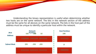
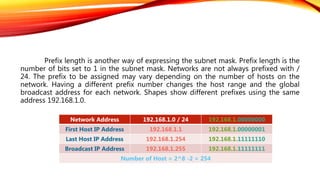
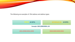
By:
Atakan ATAK
Network Engineer
atakannatak@hotmail.com
February 21, 2018
TOPICS OF PRESENTATION
 Introduction
 IPv4 Network Address
 IPv4 Address Types
 Subnetting an IPv4 Network
 VLSM
 IPv6 Network Address
 NAT
The IP (Internet Protocol) address is the identifying number of a device that
uses Internet technology for communication in a computer network. The IP address
identifies which service provider or network the device is using, and from which
location it is connected to the Internet. The Internet Service Provider (ISP) defines a
unique IP address for each device connected to the internet.
1. Introduction
Addressing is one of the main functions of network layer protocols that
provide data communication between network devices regardless of whether they are
on the same or different network. To understand the operation of devices on the
network, we need to look at the addresses and other devices, such as the binary
representation.
An IPv4 address has 32 bits divided into four octets. To make the address
easier to read, people use decimal numbers to represent the binary digits. The dotted
decimal notation that represents the spelling of binary IP addresses in decimal format
is shown as an example on the next slide.
2. IPv4 Network Address
Let’ s examine the representation of the 192.168.52.106 network as an
example;
128 64 32 16 8 4 2 1
192 1 1 0 0 0 0 0 0
168 1 0 1 0 1 0 0 0
52 0 0 1 1 0 1 0 0
106 0 1 1 0 1 0 1 0
Table 1: Binary to decimal conversion
Classified IP addresses were defined for specific size networks and specific
address blocks for those networks. An entire network was assigned to a company or
organization from an IP address block that was classified. This use of the address field
is referred to as classed addressing.
3. IPv4 Network Address Types
Address
Class
Decimal
Octet
Binary First Octet Network(N) and
Host(H)
Subnet Mask Possible Numbers
A 1-127 00000000-01111111 N.H.H.H 255.0.0.0 128 Network
16.777.214 Host
B 128-191 10000000-10111111 N.N.H.H 255.255.0.0 16.384 Network
65.534 Host
C 192-223 11000000-11011111 N.N.N.H 255.255.255.0 2.097.150 Network
254 Host
D 224-239 11100000-11101111 NA (Multicast)
E 240-255 11110000-11111111 NA (Scientific)
Table 2: Class of IP address
Subnetting is the process of segmenting a network into multiple smaller
network spaces called subnets. Large networks must be segmented into smaller
subnets, creating smaller groups of devices and services to;
4. Subnetting an IPv4 Network Address
 Control traffic by containing broadcast traffic within each subnet
 Reduce overall network traffic and improve network performance
 Simplified management
 Facilitated spanning of large geographical distances
To create subnets, you take bits from the host partion of the IP address and
reserve them to define subnet address. This means fewer bits for hosts, so the more
subnets, the fewer bits left available for defining hosts.
1. Determine the number of required network IDs:
2. Determine the number of required host IDs per subnet:
3. Based on the previous requirements, create the following:
 One for each subnet
 One for each wide area network connection
 One subnet mask for your entire network
 A unique subnet ID for each pyhsical segment
 A range of host IDs for each subnet
 One for each TCP/IP host
 One for each router interface
Understanding the binary representation is useful when determining whether
two hosts are on the same network. The bits in the network section of the address
must be the same for all devices on the same network. The bits in the host part of the
address must be unique to identify a particular host within the network.
11000000 . 10101000 . 00110100 01101010
IPv4
Address
Subnet Mask
Network
Partition
Host Partition
11111111 . 11111111 . 11111111 00000000
192 .168 .52
255 . 255 .255
.106
.0
Prefix length is another way of expressing the subnet mask. Prefix length is the
number of bits set to 1 in the subnet mask. Networks are not always prefixed with /
24. The prefix to be assigned may vary depending on the number of hosts on the
network. Having a different prefix number changes the host range and the global
broadcast address for each network. Shapes show different prefixes using the same
address 192.168.1.0.
Network Address 192.168.1.0 / 24 192.168.1.00000000
First Host IP Address 192.168.1.1 192.168.1.00000001
Last Host IP Address 192.168.1.254 192.168.1.11111110
Broadcast IP Address 192.168.1.255 192.168.1.11111111
Number of Host = 2^8 -2 = 254
Network Address 192.168.1.0 / 25 192.168.1.00000000
First Host IP Address 192.168.1.1 192.168.1.00000001
Last Host IP Address 192.168.1.126 192.168.1.01111110
Broadcast IP Address 192.168.1.127 192.168.1.01111111
Number of Host = 2^7 -2 = 126
Network Address 192.168.1.0 / 26 192.168.1.00000000
First Host IP Address 192.168.1.1 192.168.1.00000001
Last Host IP Address 192.168.1.62 192.168.1.00111110
Broadcast IP Address 192.168.1.63 192.168.1.00111111
Number of Host = 2^6 -2 = 62
The first 3 networks created for the partitioning of 172.16.10.0 network into 8
subnets are shown below.
Network 0
Network
First
Last
Broadcast
172 .16 .10 .000 0 0000 172.16.10.1
172 .16 .10 .000 0 0001 172.16.10.1
172 .16 .10 .000 1 1110 172.16.10.30
172 .16 .10 .000 1 1111 172.16.10.31
Network 1
Network
First
Last
Broadcast
172 .16 .10 .001 0 0000 172.16.10.32
172 .16 .10 .001 0 0001 172.16.10.33
172 .16 .10 .001 1 1110 172.16.10.62
172 .16 .10 .001 1 1111 172.16.10.63
Network 2
Network
First
Last
Broadcast
172 .16 .10 .010 0 0000 172.16.10.64
172 .16 .10 .010 0 0001 172.16.10.65
172 .16 .10 .010 1 1110 172.16.10.94
172 .16 .10 .010 1 1111 172.16.10.95
5. VLSM
When allocating to a fixed subnet, the number of users in each subnet is the same. In real life,
however, the number of devices in subnets is usually not equal. In traditional subnetting, we distinguish
it to meet the largest LAN requirements. But when we divided the address space to a sufficient number
of subnets, we waste the extra devices addresses we do not use.
For example, 2 host addresses are used for a WAN link. For example, if we consider that
192.168.1.0/24 is divided into 4, we need to borrow 2 bits of host bits. That is, only 2 hosts are used for
WAN connection in each subnet. The remaining 58 hosts are wasted here.
A variable-length subnet mask can be used to prevent this situation. When using VLSM, the
subnet mask will vary depending on how many host bits are borrowed for a given subnet. When using
VLSM, the network is first divided into subnets, then the subnets are separated from the subnetwork
again. This process can be repeated multiple times to create subnets in various sizes. LAN and WAN
segments can be addressed without wasting IP addresses using VLSM.
The VLSM operation is performed in accordance with the requirements of the WAN links (2
hosts) for the latest network created after the subnet allocation for the 192.168.20.0 /24 network.
1100000000 . 10101000 . 00010100 . 000 00000 192.168.20.0 / 24
1100000000 . 10101000 . 00010100 . 000 00000 192.168.20.0 / 27
1100000000 . 10101000 . 00010100 . 001 00000 192.168.20.32 / 27
1100000000 . 10101000 . 00010100 . 010 00000 192.168.20.64 / 27
1100000000 . 10101000 . 00010100 . 011 00000 192.168.20.96 / 27
1100000000 . 10101000 . 00010100 . 100 00000 192.168.20.128 / 27
1100000000 . 10101000 . 00010100 . 110 00000 192.168.20.160 / 27
1100000000 . 10101000 . 00010100 . 111 00000 192.168.20.192 / 27
1100000000 . 10101000 . 00010100 . 111000 00 192.168.20.224 / 30
1100000000 . 10101000 . 00010100 . 111 00000 192.168.20.224 / 27
1100000000 . 10101000 . 00010100 . 111001 00 192.168.20.228 / 30
1100000000 . 10101000 . 00010100 . 111010 00 192.168.20.232 / 30
1100000000 . 10101000 . 00010100 . 111011 00 192.168.20.236 / 30
1100000000 . 10101000 . 00010100 . 111100 00 192.168.20.240 / 30
1100000000 . 10101000 . 00010100 . 111101 00 192.168.20.244 / 30
1100000000 . 10101000 . 00010100 . 111110 00 192.168.20.248 / 30
1100000000 . 10101000 . 00010100 . 111111 00 192.168.20.252 / 30
Network 0
Network 1
Network 2
Network 3
Network 4
Network 5
Network 6
Network 7
Network 7.0
Network 7.1
Network 7.2
Network 7.3
Network 7.4
Network 7.5
Network 7.6
Network 7.7
V
L
S
M
S
C
H
E
M
E
The following are the subjects in which the IPv4 address is insufficient;
6. IPv6 Network Address
 It is insufficient for end-to-end addressing
 To prevent the inadequate number of address, Address translation mechanisms such as NAT
have been developed and become mandatory
 Does not authorize for hierarchical addressing
 Insufficient to meet the increased Quality of Service needs
 The need for security at the IP level has been increased to protect the confidentiality and
integrity of the data. IPv4 has become unresponsive to this request.
The following are some of the advantages of IPv6 addressing;
 New Security Features
 Simplified Title Structure & Easy and Efficient Routing
 Advanced Quality of Service Features
 Automatic Address Configuration
 Synchronous transmission of data to many destinations on a network (Multicasting)
The following are examples of IPv6 address and address types;
PREFIX
2001:0DB8:000A:0000
INTERFACE ID
0000:0000:0000:0000
Example: 2001:0DB8:000A::/64
(64 BITS) (64 BITS)
INTERFACE ID
LINK LOCAL
LOOPBACK
::1/128
UNSPECIFIED ADDRESSES
::1/128
GLOBAL UNICAST
UNIQUE LOCAL
FC00::/7 – FCFF::/7
PART OF IPV4 FOR CHANGING TO
IPV6 ADDRESS
IPV4 ADDRESS IPV6 ADDRESS
Address Length – 32 Bits Address Length – 128 Bits
Header Length – 20 Bytes Header Length – 40 Bytes
Address Representation – Decimal Address Representation – Hexadecimal
Internet Address Classes Not Applicable In IPv6
Multicast Address – 224.0.0.0 / 4 Multicast Address – FF00::/8
Broadcast Address Not Applicable In IPv6
Unspicified Address is 0.0.0.0 Unspicified Address is ::
Loopback Address is 127.0.0.1 Loopback Address is ::1
Public IP Address Global IP Address
Private IP Address
10.0.0.0 / 8 | 172.16.0.0 / 12 | 192.168.0.0 / 16
Private IP Address
FEC0::/10
COMPARING BETWEEN IPV4 & IPV6
7. NAT
The rapid growth of the Internet resulted in a shortage of available IPv4 addresses. In response,
a specific subset of the IPv4 address space was designated as private, to temporarily alleviate this
problem.
A public address can be routed on the Internet. Thus, devices that must be Internet-accessible
must be configured with (or reachable by) public addresses. Allocation of public addresses is governed by
the Internet Assigned Numbers Authority (IANA).
A private address is intended for internal use within a home or organization, and can be freely
used by anyone. However, private addresses can never be routed on the Internet. In fact, Internet routers
are configured to immediately drop traffic with private addresses.
NAT allows private IP addresses to be translated into public IP addresses. It is to protect the
general IPv4 addresses of the primary usage purposes. NAT for this reason allows networks to use specific
IPv4 addresses internally and to translate global addresses only when necessary. Another advantage NAT
has inherited is that it hides internal IPv4 addresses from external networks, thereby increasing network
security and security.
An NAT router typically operates at the edge of single-link networks. Single-link networks are
networks that have a single connection to the neighboring network, one entry and one exit.
In NAT construction, the internal network is a set of networks that are subject to translation. The
external network refers to all the remaining networks. In addition, the IPv4 addresses are represented as
follows according to the incoming and outgoing traffic, and the IPv4 addresses in the private or public
network.
Internet
192.168.10.10
192.168.10.1 10.1.1.1 30.1.1.1 172.16.10.1
Static NAT Translation
30.1.1.2  172.16.10.5
INSIDE LOCAL ADDRESS – 192.168.10.10
INSIDE GLOBAL ADDRESS – 10.1.1.1
OUTSIDE GLOBAL ADDRESS – 30.1.1.2
OUTSIDE LOCAL ADDRESS – 30.1.1.2
172.16.10.1
Internet
192.168.10.10
192.168.10.1 10.1.1.1 30.1.1.1 172.16.10.1
Static NAT Translation
30.1.1.2  172.16.10.5
SRC Address -- 192.168.10.10
DST Address -- 30.1.1.2
SRC Address -- 10.1.1.1 : 31092
DST Address -- 30.1.1.2
SRC Address -- 10.1.1.1 : 31092
DST Address -- 172.16.10.1
172.16.10.1
NAT provides the following benefits;
NAT provides the following disadvantages;
 Conserves public IP addresses
 Hides your internal IP addressing scheme from the outside world, greatly enhancing network
security
 Allows for easy renumbering of your IP addresses
 Greater flexibility in ISP service
 Introduces a small amount of delay into your network, because the NAT router has to create
and maintain the NAT table
 End to end IP traceability is lost
 Performance reduction

IP Addressing and Subnetting

  • 1.
  • 2.
    TOPICS OF PRESENTATION Introduction  IPv4 Network Address  IPv4 Address Types  Subnetting an IPv4 Network  VLSM  IPv6 Network Address  NAT
  • 3.
    The IP (InternetProtocol) address is the identifying number of a device that uses Internet technology for communication in a computer network. The IP address identifies which service provider or network the device is using, and from which location it is connected to the Internet. The Internet Service Provider (ISP) defines a unique IP address for each device connected to the internet. 1. Introduction
  • 4.
    Addressing is oneof the main functions of network layer protocols that provide data communication between network devices regardless of whether they are on the same or different network. To understand the operation of devices on the network, we need to look at the addresses and other devices, such as the binary representation. An IPv4 address has 32 bits divided into four octets. To make the address easier to read, people use decimal numbers to represent the binary digits. The dotted decimal notation that represents the spelling of binary IP addresses in decimal format is shown as an example on the next slide. 2. IPv4 Network Address
  • 5.
    Let’ s examinethe representation of the 192.168.52.106 network as an example; 128 64 32 16 8 4 2 1 192 1 1 0 0 0 0 0 0 168 1 0 1 0 1 0 0 0 52 0 0 1 1 0 1 0 0 106 0 1 1 0 1 0 1 0 Table 1: Binary to decimal conversion
  • 6.
    Classified IP addresseswere defined for specific size networks and specific address blocks for those networks. An entire network was assigned to a company or organization from an IP address block that was classified. This use of the address field is referred to as classed addressing. 3. IPv4 Network Address Types Address Class Decimal Octet Binary First Octet Network(N) and Host(H) Subnet Mask Possible Numbers A 1-127 00000000-01111111 N.H.H.H 255.0.0.0 128 Network 16.777.214 Host B 128-191 10000000-10111111 N.N.H.H 255.255.0.0 16.384 Network 65.534 Host C 192-223 11000000-11011111 N.N.N.H 255.255.255.0 2.097.150 Network 254 Host D 224-239 11100000-11101111 NA (Multicast) E 240-255 11110000-11111111 NA (Scientific) Table 2: Class of IP address
  • 7.
    Subnetting is theprocess of segmenting a network into multiple smaller network spaces called subnets. Large networks must be segmented into smaller subnets, creating smaller groups of devices and services to; 4. Subnetting an IPv4 Network Address  Control traffic by containing broadcast traffic within each subnet  Reduce overall network traffic and improve network performance  Simplified management  Facilitated spanning of large geographical distances
  • 8.
    To create subnets,you take bits from the host partion of the IP address and reserve them to define subnet address. This means fewer bits for hosts, so the more subnets, the fewer bits left available for defining hosts. 1. Determine the number of required network IDs: 2. Determine the number of required host IDs per subnet: 3. Based on the previous requirements, create the following:  One for each subnet  One for each wide area network connection  One subnet mask for your entire network  A unique subnet ID for each pyhsical segment  A range of host IDs for each subnet  One for each TCP/IP host  One for each router interface
  • 9.
    Understanding the binaryrepresentation is useful when determining whether two hosts are on the same network. The bits in the network section of the address must be the same for all devices on the same network. The bits in the host part of the address must be unique to identify a particular host within the network. 11000000 . 10101000 . 00110100 01101010 IPv4 Address Subnet Mask Network Partition Host Partition 11111111 . 11111111 . 11111111 00000000 192 .168 .52 255 . 255 .255 .106 .0
  • 10.
    Prefix length isanother way of expressing the subnet mask. Prefix length is the number of bits set to 1 in the subnet mask. Networks are not always prefixed with / 24. The prefix to be assigned may vary depending on the number of hosts on the network. Having a different prefix number changes the host range and the global broadcast address for each network. Shapes show different prefixes using the same address 192.168.1.0. Network Address 192.168.1.0 / 24 192.168.1.00000000 First Host IP Address 192.168.1.1 192.168.1.00000001 Last Host IP Address 192.168.1.254 192.168.1.11111110 Broadcast IP Address 192.168.1.255 192.168.1.11111111 Number of Host = 2^8 -2 = 254
  • 11.
    Network Address 192.168.1.0/ 25 192.168.1.00000000 First Host IP Address 192.168.1.1 192.168.1.00000001 Last Host IP Address 192.168.1.126 192.168.1.01111110 Broadcast IP Address 192.168.1.127 192.168.1.01111111 Number of Host = 2^7 -2 = 126 Network Address 192.168.1.0 / 26 192.168.1.00000000 First Host IP Address 192.168.1.1 192.168.1.00000001 Last Host IP Address 192.168.1.62 192.168.1.00111110 Broadcast IP Address 192.168.1.63 192.168.1.00111111 Number of Host = 2^6 -2 = 62
  • 12.
    The first 3networks created for the partitioning of 172.16.10.0 network into 8 subnets are shown below. Network 0 Network First Last Broadcast 172 .16 .10 .000 0 0000 172.16.10.1 172 .16 .10 .000 0 0001 172.16.10.1 172 .16 .10 .000 1 1110 172.16.10.30 172 .16 .10 .000 1 1111 172.16.10.31 Network 1 Network First Last Broadcast 172 .16 .10 .001 0 0000 172.16.10.32 172 .16 .10 .001 0 0001 172.16.10.33 172 .16 .10 .001 1 1110 172.16.10.62 172 .16 .10 .001 1 1111 172.16.10.63 Network 2 Network First Last Broadcast 172 .16 .10 .010 0 0000 172.16.10.64 172 .16 .10 .010 0 0001 172.16.10.65 172 .16 .10 .010 1 1110 172.16.10.94 172 .16 .10 .010 1 1111 172.16.10.95
  • 13.
    5. VLSM When allocatingto a fixed subnet, the number of users in each subnet is the same. In real life, however, the number of devices in subnets is usually not equal. In traditional subnetting, we distinguish it to meet the largest LAN requirements. But when we divided the address space to a sufficient number of subnets, we waste the extra devices addresses we do not use. For example, 2 host addresses are used for a WAN link. For example, if we consider that 192.168.1.0/24 is divided into 4, we need to borrow 2 bits of host bits. That is, only 2 hosts are used for WAN connection in each subnet. The remaining 58 hosts are wasted here. A variable-length subnet mask can be used to prevent this situation. When using VLSM, the subnet mask will vary depending on how many host bits are borrowed for a given subnet. When using VLSM, the network is first divided into subnets, then the subnets are separated from the subnetwork again. This process can be repeated multiple times to create subnets in various sizes. LAN and WAN segments can be addressed without wasting IP addresses using VLSM.
  • 14.
    The VLSM operationis performed in accordance with the requirements of the WAN links (2 hosts) for the latest network created after the subnet allocation for the 192.168.20.0 /24 network. 1100000000 . 10101000 . 00010100 . 000 00000 192.168.20.0 / 24 1100000000 . 10101000 . 00010100 . 000 00000 192.168.20.0 / 27 1100000000 . 10101000 . 00010100 . 001 00000 192.168.20.32 / 27 1100000000 . 10101000 . 00010100 . 010 00000 192.168.20.64 / 27 1100000000 . 10101000 . 00010100 . 011 00000 192.168.20.96 / 27 1100000000 . 10101000 . 00010100 . 100 00000 192.168.20.128 / 27 1100000000 . 10101000 . 00010100 . 110 00000 192.168.20.160 / 27 1100000000 . 10101000 . 00010100 . 111 00000 192.168.20.192 / 27 1100000000 . 10101000 . 00010100 . 111000 00 192.168.20.224 / 30 1100000000 . 10101000 . 00010100 . 111 00000 192.168.20.224 / 27 1100000000 . 10101000 . 00010100 . 111001 00 192.168.20.228 / 30 1100000000 . 10101000 . 00010100 . 111010 00 192.168.20.232 / 30 1100000000 . 10101000 . 00010100 . 111011 00 192.168.20.236 / 30 1100000000 . 10101000 . 00010100 . 111100 00 192.168.20.240 / 30 1100000000 . 10101000 . 00010100 . 111101 00 192.168.20.244 / 30 1100000000 . 10101000 . 00010100 . 111110 00 192.168.20.248 / 30 1100000000 . 10101000 . 00010100 . 111111 00 192.168.20.252 / 30 Network 0 Network 1 Network 2 Network 3 Network 4 Network 5 Network 6 Network 7 Network 7.0 Network 7.1 Network 7.2 Network 7.3 Network 7.4 Network 7.5 Network 7.6 Network 7.7 V L S M S C H E M E
  • 15.
    The following arethe subjects in which the IPv4 address is insufficient; 6. IPv6 Network Address  It is insufficient for end-to-end addressing  To prevent the inadequate number of address, Address translation mechanisms such as NAT have been developed and become mandatory  Does not authorize for hierarchical addressing  Insufficient to meet the increased Quality of Service needs  The need for security at the IP level has been increased to protect the confidentiality and integrity of the data. IPv4 has become unresponsive to this request.
  • 16.
    The following aresome of the advantages of IPv6 addressing;  New Security Features  Simplified Title Structure & Easy and Efficient Routing  Advanced Quality of Service Features  Automatic Address Configuration  Synchronous transmission of data to many destinations on a network (Multicasting)
  • 17.
    The following areexamples of IPv6 address and address types; PREFIX 2001:0DB8:000A:0000 INTERFACE ID 0000:0000:0000:0000 Example: 2001:0DB8:000A::/64 (64 BITS) (64 BITS)
  • 18.
    INTERFACE ID LINK LOCAL LOOPBACK ::1/128 UNSPECIFIEDADDRESSES ::1/128 GLOBAL UNICAST UNIQUE LOCAL FC00::/7 – FCFF::/7 PART OF IPV4 FOR CHANGING TO IPV6 ADDRESS
  • 19.
    IPV4 ADDRESS IPV6ADDRESS Address Length – 32 Bits Address Length – 128 Bits Header Length – 20 Bytes Header Length – 40 Bytes Address Representation – Decimal Address Representation – Hexadecimal Internet Address Classes Not Applicable In IPv6 Multicast Address – 224.0.0.0 / 4 Multicast Address – FF00::/8 Broadcast Address Not Applicable In IPv6 Unspicified Address is 0.0.0.0 Unspicified Address is :: Loopback Address is 127.0.0.1 Loopback Address is ::1 Public IP Address Global IP Address Private IP Address 10.0.0.0 / 8 | 172.16.0.0 / 12 | 192.168.0.0 / 16 Private IP Address FEC0::/10 COMPARING BETWEEN IPV4 & IPV6
  • 20.
    7. NAT The rapidgrowth of the Internet resulted in a shortage of available IPv4 addresses. In response, a specific subset of the IPv4 address space was designated as private, to temporarily alleviate this problem. A public address can be routed on the Internet. Thus, devices that must be Internet-accessible must be configured with (or reachable by) public addresses. Allocation of public addresses is governed by the Internet Assigned Numbers Authority (IANA). A private address is intended for internal use within a home or organization, and can be freely used by anyone. However, private addresses can never be routed on the Internet. In fact, Internet routers are configured to immediately drop traffic with private addresses. NAT allows private IP addresses to be translated into public IP addresses. It is to protect the general IPv4 addresses of the primary usage purposes. NAT for this reason allows networks to use specific IPv4 addresses internally and to translate global addresses only when necessary. Another advantage NAT has inherited is that it hides internal IPv4 addresses from external networks, thereby increasing network security and security.
  • 21.
    An NAT routertypically operates at the edge of single-link networks. Single-link networks are networks that have a single connection to the neighboring network, one entry and one exit. In NAT construction, the internal network is a set of networks that are subject to translation. The external network refers to all the remaining networks. In addition, the IPv4 addresses are represented as follows according to the incoming and outgoing traffic, and the IPv4 addresses in the private or public network. Internet 192.168.10.10 192.168.10.1 10.1.1.1 30.1.1.1 172.16.10.1 Static NAT Translation 30.1.1.2  172.16.10.5 INSIDE LOCAL ADDRESS – 192.168.10.10 INSIDE GLOBAL ADDRESS – 10.1.1.1 OUTSIDE GLOBAL ADDRESS – 30.1.1.2 OUTSIDE LOCAL ADDRESS – 30.1.1.2 172.16.10.1
  • 22.
    Internet 192.168.10.10 192.168.10.1 10.1.1.1 30.1.1.1172.16.10.1 Static NAT Translation 30.1.1.2  172.16.10.5 SRC Address -- 192.168.10.10 DST Address -- 30.1.1.2 SRC Address -- 10.1.1.1 : 31092 DST Address -- 30.1.1.2 SRC Address -- 10.1.1.1 : 31092 DST Address -- 172.16.10.1 172.16.10.1
  • 23.
    NAT provides thefollowing benefits; NAT provides the following disadvantages;  Conserves public IP addresses  Hides your internal IP addressing scheme from the outside world, greatly enhancing network security  Allows for easy renumbering of your IP addresses  Greater flexibility in ISP service  Introduces a small amount of delay into your network, because the NAT router has to create and maintain the NAT table  End to end IP traceability is lost  Performance reduction