Internet Protocol (IP)
The Internet Protocol (IP) is a protocol used for communicating
data across a packet-switched internetwork using the Internet
Protocol Suite, also referred to as TCP/IP.
IP is the primary protocol in the Internet Layer which has the task
of delivering packets from the source host to the destination host
solely based on their addresses.
Communication at the network layer is host-to-host (computer-to-
computer); a computer somewhere in the world needs to
communicate with another computer somewhere else in the world.
2
3.
Usually, computerscommunicate through the Internet (worldwide NW).
The packet transmitted by the sending computer may pass through several
LANs or WANs before reaching the destination computer.
For this level of communication, we need a global addressing scheme; we use
the term IP address to mean a logical address in the network layer of the
TCP/IP protocol suite.
The first major version of addressing structure, Internet Protocol Version 4
(IPv4) is still the dominant protocol of the Internet, although the successor,
Internet Protocol Version 6 (IPv6), is being deployed actively worldwide (128
bits).
3
Cont’d …
4.
IPv4 Addresses
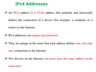
AnIPv4 address is a 32-bit address that uniquely and universally
defines the connection of a device (for example, a computer or a
router) to the Internet.
IPv4 addresses are unique and universal.
They are unique in the sense that each address defines one, and only
one, connection to the Internet.
Two devices on the Internet can never have the same address at the
same time.
4
5.
Address Space
Aprotocol such as IPv4 that defines addresses has an address space.
An address space is the total number of addresses used by the protocol.
If a protocol uses N bits to define an address, the address space is 2N
because each bit can have two different values (0 or 1) and N bits can
have 2N
values.
IPv4 uses 32-bit addresses, which means that the address space is 232
or
4,294,967,296 (more than 4 billion). This means that, theoretically, if
there were no restrictions, more than 4 billion devices could be
connected to the Internet.
We will see shortly that the actual number is much less because of the
restrictions imposed on the addresses.
5
6.
Notations
There aretwo prevalent notations to show an 1Pv4 address: binary
notation and dotted-decimal notation.
Binary Notation
In binary notation, the IPv4 address is displayed as 32 bits. Each
octet is often referred to as a byte. IPv4 address which uses 32-bit
address has 4 octet (4-byte).
Example of an IPv4 address in binary notation:
01110101 10010101 00011101 00000010
Dotted-Decimal Notation
To make the IPv4 address more compact and easier to read, Internet
addresses are usually written in decimal form with a decimal point
(dot) separating the bytes.
Example: The dotted-decimal notation of the above address:
117.149.29.2 6
8
Change the followingIPv4 addresses from binary notation
to dotted-decimal notation.
Example 1
Solution
We replace each group of 8 bits with its equivalent decimal
number and add dots for separation.
9.
9
Change the followingIPv4 addresses from dotted-decimal
notation to binary notation.
Example 2
Solution
We replace each decimal number with its binary equivalent.
10.
10
Find the error,if any, in the following IPv4 addresses.
Example 3
Solution
a. There must be no leading zero (045).
b. There can be no more than four numbers.
c. Each number needs to be less than or equal to 255.
d. A mixture of binary notation and dotted-decimal
notation is not allowed.
11.
Classful Addressing
• IPv4addressing, at its inception, used the concept of classes. This
architecture is called classful addressing.
• In classful addressing, the address space is divided into five classes: A,
B, C, D, and E. Each class occupies some part of the address space.
11
12.
12
Find the classof each address.
a. 00000001 00001011 00001011 11101111
b. 11000001 10000011 00011011 11111111
c. 14.23.120.8
d. 252.5.15.111
Example 4
Solution
a. The first bit is 0. This is a class A address.
b. The first 2 bits are 1; the third bit is 0. This is a class C
address.
c. The first byte is 14; the class is A.
d. The first byte is 252; the class is E.
13.
Classes and Blocks
•One problem with classful addressing is that each class is
divided into a fixed number of blocks with each block having a
fixed size
Number of Blocks for class A = 27
Number of Blocks for class B = 214
Number of Blocks for class C = 221
Block size for class A = 224
Block size for class B = 216
Block size for class C = 28
13
14.
Previously, whenan organization requested a block of addresses, it was
granted one in class A, B, or C.
Class A addresses were designed for large organizations with a large
number of attached hosts or routers.
Class B addresses were designed for midsize organizations with tens of
thousands of attached hosts or routers.
Class C addresses were designed for small organizations with a small
number of attached hosts or routers.
A block in class A address is too large for almost any organization. This
means most of the addresses in class A were wasted and were not used.
A block in class B is also very large, probably too large for many of the
organizations that received a class B block.
A block in class C is probably too small for many organizations.
14
Contd.
15.
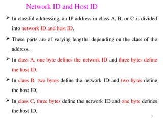
Network ID andHost ID
In classful addressing, an IP address in class A, B, or C is divided
into network ID and host ID.
These parts are of varying lengths, depending on the class of the
address.
In class A, one byte defines the network ID and three bytes define
the host ID.
In class B, two bytes define the network ID and two bytes define
the host ID.
In class C, three bytes define the network ID and one byte defines
the host ID.
15
16.
Mask
Although thelength of the network ID and host ID (in bits) is
predetermined in classful addressing, we can also use a mask (also called
the default mask), a 32-bit number made of contiguous 1s followed by
contiguous 0s.
The mask can help us to find the network ID and the host ID.
For example, the mask for a class A address has eight 1 s, which means the
first 8 bits of any address in class A define the network ID; the next 24 bits
define the host ID.
The masks for classes A, B, and C are shown below
16
17.
Subnetting
Subnet isa way of partitioning a IP address into a block of
addresses.
It is dividing the addresses into several groups and assign each
group to smaller networks
Is a logical subdivision of an IP network.
There are two types of Subnetting FLSM and VLSM.
In FLSM, all subnets have equal number of host addresses and use
same Subnet mask.
In VLSM, subnets have flexible number of host addresses and use
different subnet mask.
17
18.
How to CreateSubnets?
To create sub networks, you take bits from the host portion of the
IP address.
Subnet consider the following:
1. How many subnets do we have?
2. What is the block size
3. What are the valid subnet?
4. How many valid hosts per subnet are available?
5. What are the valid hosts in each subnet?
6. What’s the broadcast address of each subnet?
18
FLSM (Fixed Length Sub-netting Mask)
19.
i. How manysubnets? number of subnets = 2x
, where x is the number
of masked bits (1s). E.g, in 11000000, the number of 1s is 2, so 22
subnets, there are 4 subnets.
ii. Block size = 256 – subnet mask
E.g, 256 – 192 = 64.
What are the valid subnets? 0, 64, 128, 192.
iii. How many hosts per subnet? number of hosts per subnet = 2y
– 2,
where y is the number of unmasked bits (0s).
E.g, in 11000000, the number of 0s is 6, so
26
– 2 hosts, there are 62 hosts per subnet.
19
20.
Cont’d…
IV. What arethe valid hosts?
The numbers between subnet address and broadcast address.
E.g, if 0 is the subnet number, then 1–62 is the valid host range.
V. What’s the broadcast address for each subnet?
The number right before the next subnet.
E.g, the 0 subnet has a broadcast address of 63 because the next subnet is
64.
20
21.
21
192.168.1.0 Network address
InFLSM, even though number of hosts are different, the block size/subnet
mask is same for all networks
22.
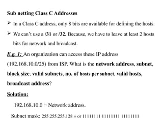
Sub netting ClassC Addresses
In a Class C address, only 8 bits are available for defining the hosts.
We can’t use a /31 or /32. Because, we have to leave at least 2 hosts
bits for network and broadcast.
E.g. 1: An organization can access these IP address
(192.168.10.0/25) from ISP. What is the network address, subnet,
block size, valid subnets, no. of hosts per subnet, valid hosts,
broadcast address?
Solution:
192.168.10.0 = Network address.
Subnet mask: 255.255.255.128 = or 11111111 11111111 11111111
23.
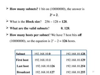
How manysubnets? 1 bit on (10000000), the answer is
21
= 2.
What is the Block size? 256 – 128 = 128.
What are the valid subnets? 0, 128.
How many hosts per subnet? We have 7 host bits off
(10000000), so the equation is 27
– 2 = 126 hosts.
Subnet 192.168.10.0 192.168.10.128
First host 192.168.10.1 192.168.10.129
Last host 192.168.10.126 192.168.10.254
Broadcast 192.168.10.127 192.168.10.255 23
24.
In class Caddressing design general format
24
Mask Bits Block
size
Subnet or host
/25 128 1 bits on and 7 bits off
(10000000)
128 2 subnets, each with 126
hosts
/26 192 2 bits on and 6 bits off
(110000000)
64 4 subnets, each with 62
hosts
/27 224 3 bits on and 5 bits off
(11100000)
32 8 subnets, each with 30
hosts
/28 240 4 bits on and 4 bits off
(11110000)
16 16 subnets, each with 14
hosts
/29 248 5 bits on and 3 bits off
(11111000)
8 32 subnets, each with 6
hosts
/30 252 6 bits on and 2 bits off
(11111100)
4 64 subnets, each with 2
hosts
25.
Sub netting inclass B
For class B, the slash notation value starts from /17.
E.g.2 An organization can access these IP address (172.16.10.0/17) from
ISP, What is the network address, subnet, block size, valid subnets,
no. of hosts per subnet, valid hosts, broadcast address? Solution
Network address = 172.16.0.0
Subnet mask = 255.255.128.0 or 11111111 11111111 10000000 00000000
Subnets? 21
= 2.
Block size? 256 – 128 = 128. Valid subnets? 0, 128
Host? 215
– 2 = 32,766 (7 bits in the third octet, and 8 in the fourth).
Remember that sub netting is performed in the third octet, so the subnet
numbers are really 0.0 and 128.0.
25
26.
Cont’d…
Valid hosts andbroadcast
Subnet 172.16.0.0 172.16.128.0
First host 172.16.0.1 172.16.128.1
Last host 172.16.127.254 172.16.255.254
Broadcast 172.16.127.255 172.16.255.255
26
27.
Sub netting inclass A
E.g.3 An organization can access these IP address (10.10.0.0/10)
from ISP, What is the network address, subnet, block size, valid
subnets, no. of hosts per subnet, valid hosts, broadcast address?
11111111 11000000 00000000 00000000 = 255.192.0.0
Subnets = 22
= 4
Block size = 256-192= 64
Valid subnets
10.0.0.0
10.64.0.0
Valid hosts = 222
-2 27
10.128.0.0
10.192.0.0
Slash Notation
SlashNotation that is used in sub netting.
The slash notation for /8 – 15 it represents class A.
The slash notation for /16- 23 it represents class A and B.
The slash notation for /24 – 30 it represents class A, B and C.
For all class /31 and /32 can not be used it reserves for host
address.
29
30.
Address Depletion
Theflaws in classful addressing scheme combined with the fast
growth of the Internet led to the near depletion of the available
addresses.
Yet the number of devices on the Internet is much less than the 232
address space.
We have run out of class A and B addresses, and a class C block is
too small for most midsize organizations.
One solution that has alleviated the problem is the idea of classless
addressing.
30
31.
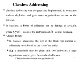
Classless Addressing
classlessaddressing was designed and implemented to overcome
address depletion and give more organizations access to the
Internet.
In classless, a block of addresses can be defined as x.y.z.t/n,
where x.y.z.t – is one of the addresses and /n - defines the mask.
Address Blocks
In classless addressing, the size of the block (the number of
addresses) varies based on the size of the entity.
E.g, a household may be given only two addresses; a large
organization may be given thousands of addresses.
This minimize address wastage in classful
31
32.
A classlesssubnet mask can be created using subnet of any class
but a classless subnet does not belong to any ‘Class’ (hence
classless).
A classless subnet exists only inside a private network e.g.,
inside an office network or a college network, etc.
32
Classless Addressing Sub-netting
33.
VLSM
Variable Length SubnetMask
Allows more than one subnet mask in the same network
More efficient use of organization’s IP address space
Subnets may significantly vary in relative size (computer
room = 200 hosts, secretary = 4 hosts…)
Consider a 4 host network with mask 255.255.255.0: wastes
250 IP addresses!
33
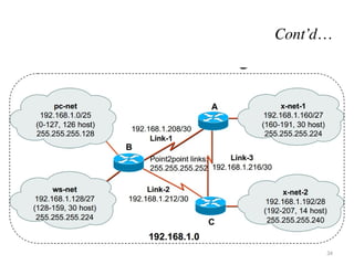
Determine what maskallows the required number of
hosts.
netB: 192.168.10.0/27 host address range 1 to 30
netE: 192.168.10.32/27 host address range 33 to 62
netA: 192.168.10.64/28 host address range 65 to 78
netD: 192.168.10.80/28 host address range 81 to 94
netC: 192.168.10.96/30 host address range 97 to 98
37
Cont’d…
38.
Classless addressing Mask
The address and the /n notation completely define the whole block
(the network address, the last address, and the number of
addresses).
The first address in the block can be found by setting the 32 - n
rightmost bits in the binary notation of the address to 0s.
38
First(Network) Address
39.
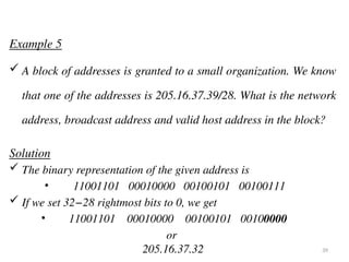
Example 5
Ablock of addresses is granted to a small organization. We know
that one of the addresses is 205.16.37.39/28. What is the network
address, broadcast address and valid host address in the block?
Solution
The binary representation of the given address is
• 11001101 00010000 00100101 00100111
If we set 32−28 rightmost bits to 0, we get
• 11001101 00010000 00100101 00100000
or
205.16.37.32 39
40.
Broadcast Address
Thebroadcast address in the block can be found by setting the 32 -
n rightmost bits in the binary notation of the address to 1s.
Example 6
Find the broadcast address for the block in Example 5.
Solution
The binary representation of the given address is
• 11001101 00010000 00100101 00100111
If we set 32 − 28 rightmost bits to 1, we get
• 11001101 00010000 00100101 00101111
or
• 205.16.37.47 40
41.
Number of Addresses
The number of addresses in the block can easily be found using
the formula 232-n
.
Example 7
Find the number of addresses in Example 5.
Solution
The value of n is 28, which means that number
of addresses is 2 32−28
or 16.
41
42.
Another wayto find the network address, the broadcast address,
and the number of addresses:
In the above example the /28 can be represented as
• 11111111 11111111 11111111 11110000
(twenty-eight 1s and four 0s).
Find
• a. The network address
• b. The broadcast address
• c. The number of addresses.
42
43.
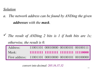
Solution
a. The networkaddress can be found by ANDing the given
addresses with the mask.
The result of ANDing 2 bits is 1 if both bits are 1s;
otherwise, the result is 0.
43
convert into decimal: 205.16.37.32
44.
b. The broadcastaddress can be found by ORing the given
addresses with the complement of the mask.
The complement of a number is found by changing each 1 to 0
and each 0 to 1.
The result of ORing 2 bits is 0 if both bits are 0s; the result is 1
otherwise.
44
convert into decimal: 205.16.37.47
45.
c. The numberof addresses can be found by complementing
the mask, interpreting it as a decimal number, and adding
1 to it.
45
46.
Network Addresses
Avery important concept in IP addressing is the network address.
When an organization is given a block of addresses, the organization
is free to allocate the addresses to the devices that need to be
connected to the Internet.
The first address in the class, however, is normally (not always) treated
as a special address.
The first address is called the network address and defines the
organization network.
It defines the organization itself to the rest of the world.
The first address is the one that is used by routers (default gateway) to
direct the message sent to the organization from the outside. 46
47.
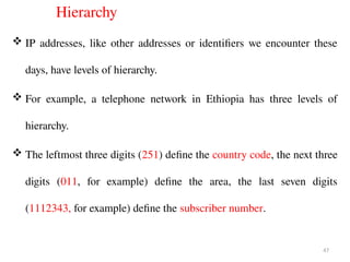
Hierarchy
IP addresses,like other addresses or identifiers we encounter these
days, have levels of hierarchy.
For example, a telephone network in Ethiopia has three levels of
hierarchy.
The leftmost three digits (251) define the country code, the next three
digits (011, for example) define the area, the last seven digits
(1112343, for example) define the subscriber number.
47
48.
Two-Level Hierarchy: NoSubnetting
An IP address can define only two levels of hierarchy when not
subnetted.
The n leftmost bits of the address x.y.z.t/n define the network
(organization network); the 32 – n rightmost bits define the particular
host (computer or router) to the network.
The two common terms are prefix and suffix.
The part of the address that defines the network is called the prefix;
the part that defines the host is called the suffix.
The prefix is common to all addresses in the network; the suffix
changes from one device to another.
48
49.
Three-Levels of Hierarchy:Subnetting
An organization that is granted a large block of addresses may want to
create clusters of networks (called subnets) and divide the addresses
between the different subnets.
The rest of the world still sees the organization as one entity; however,
internally there are several subnets.
The organization, however, needs to create small sub blocks of
addresses, each assigned to specific subnets. The organization has its
own mask; each subnet must also have its own.
All messages are sent to the router address that connects the
organization to the rest of the Internet; the router routes the message
to the appropriate subnets. 49
50.
Example 7
Supposean organization is given the block 17.12.14.0/26, which contains 64
addresses. The organization has three offices and needs to divide the
addresses into three sub blocks of 32, 16, and 16 addresses.
We can find the new masks by using the following arguments:
1. Suppose the mask for the first subnet is n1, then 232-n1
must be 32, which
means that n1 = 27.
2. Suppose the mask for the second subnet is n2, then 232-n2
must be 16,
which means that n2 = 28.
3. Suppose the mask for the third subnet is n3, then 232-n3
must be 16, which
means that n3 = 28.
This means that we have the masks 27, 28, 28 with the organization mask
being 26. 50
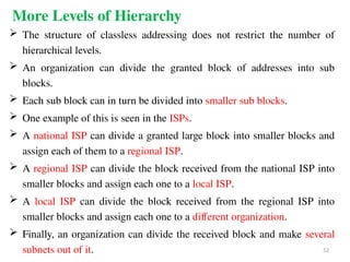
More Levels ofHierarchy
The structure of classless addressing does not restrict the number of
hierarchical levels.
An organization can divide the granted block of addresses into sub
blocks.
Each sub block can in turn be divided into smaller sub blocks.
One example of this is seen in the ISPs.
A national ISP can divide a granted large block into smaller blocks and
assign each of them to a regional ISP.
A regional ISP can divide the block received from the national ISP into
smaller blocks and assign each one to a local ISP.
A local ISP can divide the block received from the regional ISP into
smaller blocks and assign each one to a different organization.
Finally, an organization can divide the received block and make several
subnets out of it. 52
53.
Address Allocation
Thenext issue in classless addressing is address allocation. How are the
blocks allocated?
The ultimate responsibility of address allocation is given to a global
authority called the Internet Corporation for Assigned Names and
Addresses (ICANN).
However, ICANN does not normally allocate addresses to individual
organizations. It assigns a large block of addresses to an ISP.
Each ISP, in turn, divides its assigned block into smaller sub blocks and
grants the sub blocks to its customers.
In other words, an ISP receives one large block to be distributed to its
Internet users. This is called address aggregation: many blocks of
addresses are aggregated in one block and granted to one ISP. 53
54.
Example 8
AnISP is granted a block of addresses starting with
190.100.0.0/16 (65,536 addresses). The ISP needs to distribute
these addresses to three groups of customers as follows:
a. The first group has 64 customers; each needs 256
addresses.
b. The second group has 128 customers; each needs 128
addresses.
c. The third group has 128 customers; each needs 64
addresses.
Design the sub blocks and find out how many addresses are still
available after these allocations. 54
55.
solution
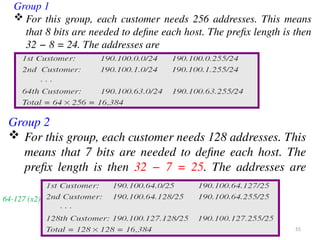
Group 1
Forthis group, each customer needs 256 addresses. This means
that 8 bits are needed to define each host. The prefix length is then
32 − 8 = 24. The addresses are
Group 2
For this group, each customer needs 128 addresses. This
means that 7 bits are needed to define each host. The
prefix length is then 32 − 7 = 25. The addresses are
55
64-127 (x2)
56.
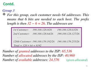
Group 3
Forthis group, each customer needs 64 addresses. This
means that 6 bits are needed to each host. The prefix
length is then 32 − 6 = 26. The addresses are
Number of granted addresses to the ISP: 65,536
Number of allocated addresses by the ISP: 40,960
Number of available addresses: 24,576 (given-allocated)
56
Contd.
57.
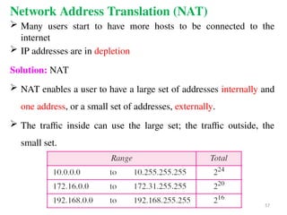
Network Address Translation(NAT)
Many users start to have more hosts to be connected to the
internet
IP addresses are in depletion
Solution: NAT
NAT enables a user to have a large set of addresses internally and
one address, or a small set of addresses, externally.
The traffic inside can use the large set; the traffic outside, the
small set.
57
IPv6 ADDRESSES
Despite allshort-term solutions, address depletion is
still a long-term problem for the Internet.
This and other problems in the IP protocol itself have
been the motivation for IPv6.
An IPv6 address is 128 bits or 32 hexadecimal digits
long.
60
61.
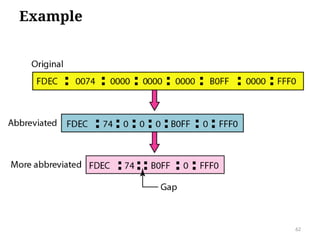
IPv6 shortening rules
61
Rule.1:Discard leading Zero(es):
Rule.2: If two of more blocks contain consecutive zeroes,
omit them all and replace with double colon sign ::
63
Expand the address0:15::1:12:1213 to its original.
Example
Solution
We first need to align the left side of the double colon to the left
of the original pattern and the right side of the double colon to
the right of the original pattern to find how many 0s we need to
replace the double colon.
This means that the original address is.
ADDRESS MAPPING
The deliveryof a packet to a host or a router requires
two levels of addressing: logical (IP) and physical (MAC).
We need to be able to map a logical address to its
corresponding physical address and vice versa.
This can be done by using either static or dynamic
mapping.
IP is used for logical addressing
MAC is used for physical addressing in a local network
such as Ethernet 65
66.
Mapping Logical toPhysical Address: ARP
Anytime a host or a router has an IP datagram to send to another
host or router, it has the logical (IP) address of the receiver.
The logical (IP) address is obtained from the DNS if the sender is
the host or it is found in a routing table if the sender is a router.
But the IP datagram must be encapsulated in a frame to be able to
pass through the physical network.
This means that the sender needs the physical address of the
receiver.
The host or the router sends an ARP query packet.
This packet includes the physical and IP addresses of the sender
and the IP address of the receiver. 66
67.
67
Because the senderdoes not know the physical address of
the receiver, the query is broadcast over the network
68.
Mapping Physical toLogical Address: RARP
Reverse Address Resolution Protocol (RARP) finds the logical
address for a machine that knows only its physical address.
There are occasions in which a host knows its physical address,
but needs to know its logical address.
This may happen in two cases:
1. A diskless station is just booted. (initially when it is booted)
The station can find its physical address by checking its
interface, but it does not know its IP address.
2. An organization does not have enough IP addresses to assign to
each station; it needs to assign IP addresses on demand.
The station can send its physical address and ask for a short
time lease. 68
69.
Sender hasits own MAC address and find IP address
To create an IP datagram, a host or a router needs to know its own IP
address or addresses.
The IP address of a machine is usually read from its configuration file
stored on a disk file.
The machine can get its physical address (by reading its NIC, for
example), which is unique locally.
It can then use the physical address to get the logical address by using
the RARP protocol.
A RARP request is created and broadcast on the local network.
Another machine (router/AP) on the local network that knows all the
IP addresses will respond with a RARP reply. 69
70.
Internet Control MessageProtocol (ICMP)
The IP protocol has no error-reporting or error-correcting
mechanism.
The IP protocol also lacks a mechanism for host and
management queries.
The ICMP has been designed to compensate for the above two
deficiencies. It is a companion to the IP protocol.
PING and TRACEROUTE are two tools for ICMP
70
71.
ICMP Types ofMessages
ICMP messages are divided into two broad categories: error-
reporting messages and query messages.
The error-reporting messages: report problems that a router
or a host (destination) may encounter when it processes an IP
packet.
The query messages: which occur in pairs, help a host or a
network manager get specific information from a router or
another host.
For example, nodes can discover their neighbors. Unreachable
Also, hosts can discover and learn about routers on their network, and
routers can help a node redirect its messages. Server down, 400,… 71
72.
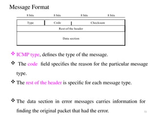
Message Format
72
ICMPtype, defines the type of the message.
The code field specifies the reason for the particular message
type.
The rest of the header is specific for each message type.
The data section in error messages carries information for
finding the original packet that had the error.
73.
Error Reporting
Oneof the main responsibilities of ICMP is to report errors.
Error checking and error control are not a concern of IP.
ICMP does not correct errors-its imply reports them.
Error correction is left to the higher-level protocols.
73
Error Reporting
74.
Internet Group ManagementProtocol (IGMP)
The IP protocol can be involved in two types of communication: uni
casting and multicasting.
Unicasting is a one-to-one communication.
However, some processes sometimes need to send the same message to a
large number of receivers simultaneously.
This is called multicasting, which is a one-to-many communication.
Multicasting has many applications. For example, travel agents can be
informed of a plane cancellation.
The IGMP is the necessary, but not sufficient, protocols that is involved
in multicasting.
IGMP is a companion to the IP protocol.
74
75.
Group Management
IGMPis not a multicasting routing protocol; it is a protocol that
manages group membership.
In any network, there are one or more multicast routers that
distribute multicast packets to hosts or other routers.
The IGMP protocol gives the multicast routers information about
the membership status of hosts (routers) connected to the
network.
A multicast router may receive thousands of multicast packets
every day for different groups. 75
76.
If arouter has no knowledge about the membership status of the
hosts, it must broad cast all these packets.
This creates a lot of traffic and consumes bandwidth.
A better solution is to keep a list of groups in the network for
which there is at least one loyal member.
IGMP helps the multicast router to create and update this list.
76
77.
Net stat Utility
Thenet stat utility can be used to find the multicast
addresses supported by an interface.
We use net stat with three options: -n, -r, and -a.
The -n option gives the numeric versions of IP addresses,
the -r option gives the routing table, and
the -a option gives all addresses (unicast and multicast).
77