Downloaded 389 times


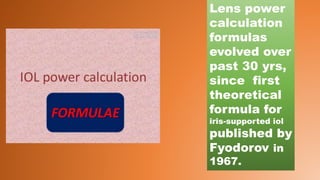
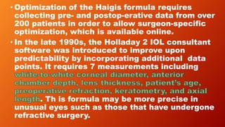
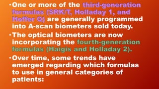
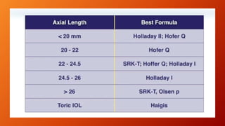
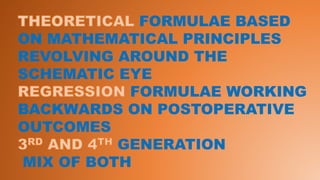
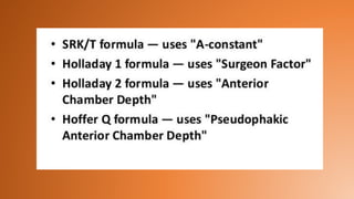
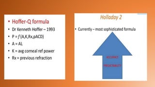
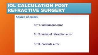
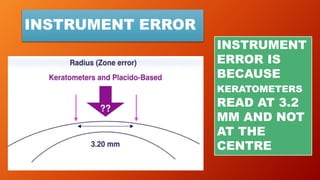
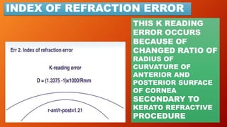
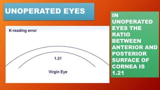
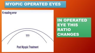
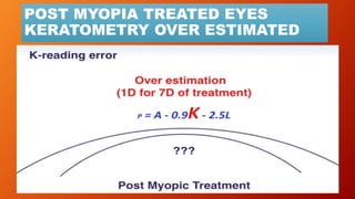
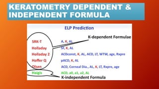
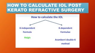
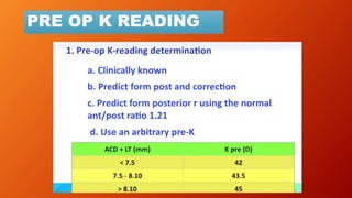
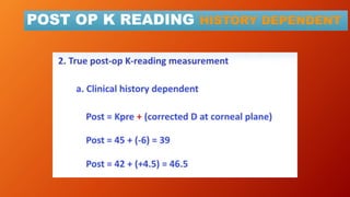
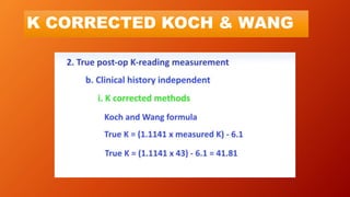
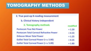
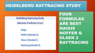
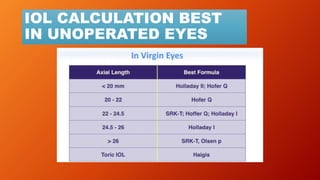
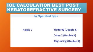


This document discusses intraocular lens (IOL) power calculation methods for eyes that have and have not undergone refractive surgery. It covers: 1. The evolution of IOL power calculation formulas from first to fourth generation formulas, which have improved accuracy by incorporating additional eye measurements and constants. 2. Sources of error in IOL power calculations from incorrect keratometry and axial length measurements. 3. Challenges in calculating IOL power for eyes that had refractive surgery due to changes in corneal shape and index of refraction. 4. Methods to estimate pre-operative keratometry and account for post-operative keratometry changes, including double-K, theoretical K, and tomography approaches.