Chapter 1 Introduction
1.Introduction(4 hours)
i. Introduction and History of Microprocessors
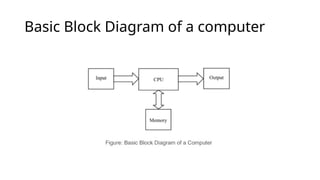
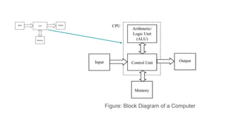
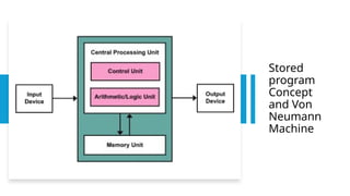
ii. Basic Block Diagram of a Computer
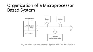
iii. Organization of Microprocessor Based System
iv. Bus Organization
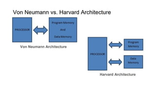
v. Stored program Concept and Von Neumann Machine
vi. Processing Cycle of a Stored Program Computer
vii. Microinstructions and Hardwired/Microprogrammed Control Unit
viii.Introduction to Register Transfer Language
Microprocessors
• A semiconductordevice consisting of electronic logic circuits
manufactured by using either a large-scale(LSI) or very –large scale
integration (VLSI) technique that is capable of performing various
computing functions and making decisions to change the sequence of
program execution.
• Microprocessor is a multipurpose programmable, clock driven,
register based electronic device that reads binary instructions from a
storage device called memory, accepts binary data as input, processes
data according to those instructions and provide result s as output.
• Consists of arithmetic and logic unit , registers and control circuitry
required to perform the functions of a computer’s central processing
unit.
5.
• It isthe Central Processing Unit(CPU),ie the main processing unit of all
computers and many household and electronic devices
• Computer processor that incorporates all the functions of CPU (Central
Processing Unit) on a single IC(Ingrates Circuit)
• Here are some key milestones in the history of microprocessors:
• 1968: Italian physicist Federico Faggin develops the first silicon-gate MOS chip
at Fairchild Semiconductor.
• 1971: Intel introduces the first commercial microprocessor, the 4-bit Intel 4004.
• 1972: Intel releases the 8-bit microprocessor Intel 8008.
• 1974: Intel releases the 8080 microprocessor, which became widely used in
personal computers and other electronic devices.
• 1978: Intel releases the 8086 microprocessor, the first 16-bit microprocessor.
• 1981: Intel introduces the 80286 microprocessor.
• 1993: Intel introduces the Pentium microprocessor.
• 1999: Intel introduces the Athlon microprocessor.
• 2003: Intel introduces the Pentium 4 microprocessor.
• 2005: Intel introduces the dual-core microprocessor.
• 2011: Intel introduces the Sandy Bridge microprocessor
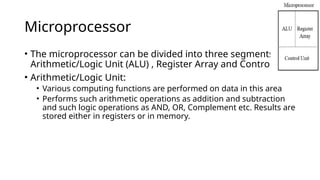
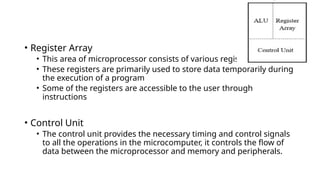
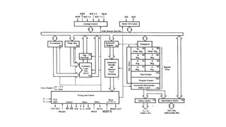
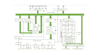
Microprocessor
• The microprocessorcan be divided into three segments as :
Arithmetic/Logic Unit (ALU) , Register Array and Control Unit
• Arithmetic/Logic Unit:
• Various computing functions are performed on data in this area
• Performs such arithmetic operations as addition and subtraction
and such logic operations as AND, OR, Complement etc. Results are
stored either in registers or in memory.
13.
• Register Array
•This area of microprocessor consists of various registers
• These registers are primarily used to store data temporarily during
the execution of a program
• Some of the registers are accessible to the user through
instructions
• Control Unit
• The control unit provides the necessary timing and control signals
to all the operations in the microcomputer, it controls the flow of
data between the microprocessor and memory and peripherals.
14.
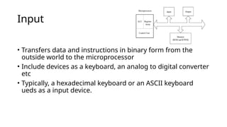
Input
• Transfers dataand instructions in binary form from the
outside world to the microprocessor
• Include devices as a keyboard, an analog to digital converter
etc
• Typically, a hexadecimal keyboard or an ASCII keyboard
ueds as a input device.
15.
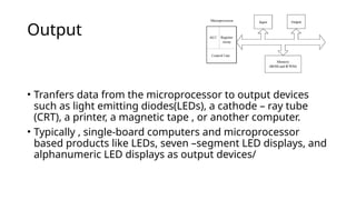
Output
• Tranfers datafrom the microprocessor to output devices
such as light emitting diodes(LEDs), a cathode – ray tube
(CRT), a printer, a magnetic tape , or another computer.
• Typically , single-board computers and microprocessor
based products like LEDs, seven –segment LED displays, and
alphanumeric LED displays as output devices/
16.
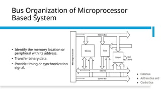
Bus Organization ofMicroprocessor
Based System
• Identify the memory location or
peripheral with its address.
• Transfer binary data
• Provide timing or synchronization
signal.
17.
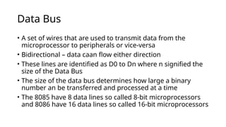
Data Bus
• Aset of wires that are used to transmit data from the
microprocessor to peripherals or vice-versa
• Bidirectional – data caan flow either direction
• These lines are identified as D0 to Dn where n signified the
size of the Data Bus
• The size of the data bus determines how large a binary
number an be transferred and processed at a time
• The 8085 have 8 data lines so called 8-bit microprocessors
and 8086 have 16 data lines so called 16-bit microprocessors
18.
Address Bus
• Aset of wires that is used to transmit address from the microprocessor
to the peripherals
• Used to select one peripheral and to enable the required devie
• After the device has been enabled the data can be transferred from the
microprocessor to the device or vice-versa
• Unidirectional-the signals flow from the MP to peripheral because only
MP sends out an address
• Identified as A0 to Am where size to address bus
• In 8085 have 16 address lines which are capable of addressing
65,536(2^16) memory location commonly known as 64k memery
• In 8086 have 20 address line.
19.
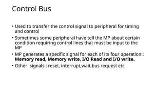
Control Bus
• Usedto transfer the control signal to peripheral for timing
and control
• Sometimes some peripheral have tell the MP about certain
condition requiring control lines that must be input to the
MP
• MP generates a specific signal for each of its four operation :
Memory read, Memory write, I/O Read and I/O write.
• Other signals : reset, interrupt,wait,bus request etc
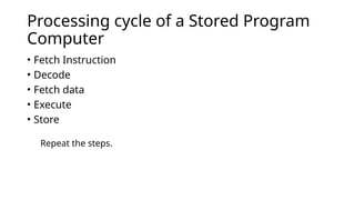
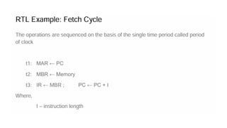
Processing cycle ofa Stored Program
Computer
• Fetch Instruction
• Decode
• Fetch data
• Execute
• Store
Repeat the steps.
24.
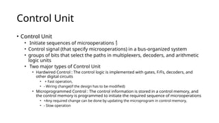
Control Unit
• ControlUnit
• Initiate sequences of microoperations
• Control signal (that specify microoperations) in a bus-organized system
• groups of bits that select the paths in multiplexers, decoders, and arithmetic
logic units
• Two major types of Control Unit
• Hardwired Control : The control logic is implemented with gates, F/Fs, decoders, and
other digital circuits
• + Fast operation,
• - Wiring change(if the design has to be modified)
• Microprogrammed Control : The control information is stored in a control memory, and
the control memory is programmed to initiate the required sequence of microoperations
• +Any required change can be done by updating the microprogram in control memory,
• - Slow operation
25.
Register Tranfer Language(RTL)
•How to describe the sequence of microoperations for given
operation?
• Specify the sequence of microoperations in a computer by
explaining every operation in words
• But this procedure involves a lengthy description explanation
• Use the symbolic notation to describe the microoperation tranfers
among registers== RTL
• A symbolic notation used to describe the microoperation
tranfers among the registers
26.
RTL
• “Register Transfer”means the availability of hardware logic
circuit that can perform a stated microoperation and
transfer the result of the operation to same or another
register
• “Language” word is borrowed from the programmers that is
used in programming
• RTL is a system for expressing in symbolic form the
microoperation sequences among the registers of a digital
module
• Can also be used to facilitate the design process of digital
sysytems