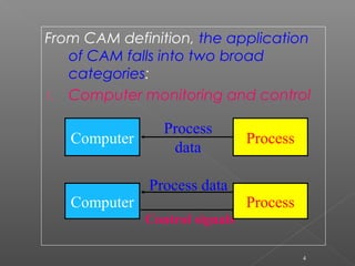
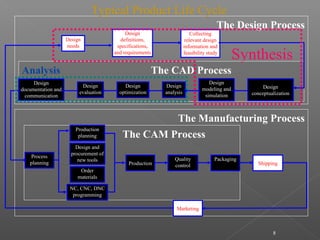
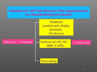
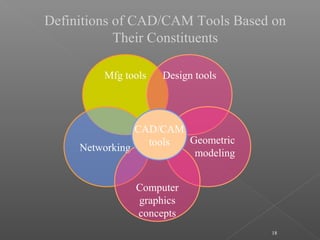
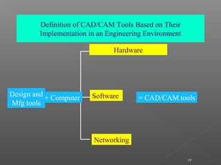
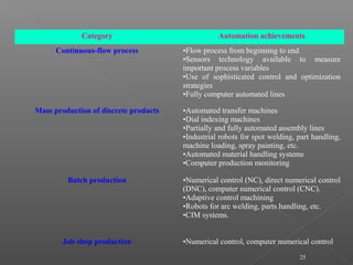
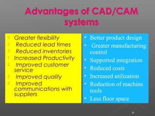
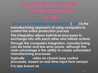
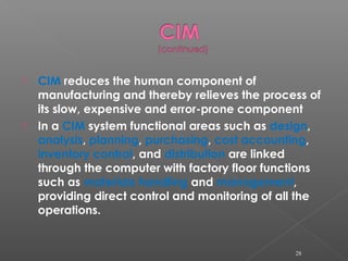
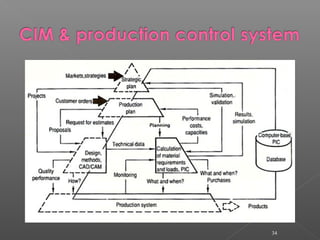
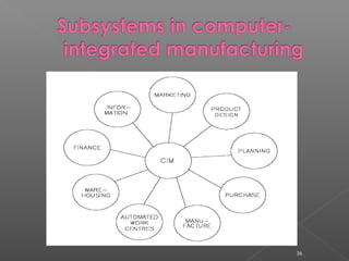
1
 CAD/CAM = Computer Aided Design/
Computer Aided Manufacturing
 It is the technology concerned with
the use of computers to perform
design and manufacturing functions
2
 CAD can be defined as the use of
computer systems to perform certain
functions in the design process
 CAM is the use of computer systems to
plan, manage and control the
operations of manufacturing plant
through either direct or indirect
computer interface with the plant’s
production resources
3
From CAM definition, the application
of CAM falls into two broad
categories:
1. Computer monitoring and control
4
Computer Process
Process
data
Control signals
Computer Process
Process data
2. Manufacturing support
application
5
Control signals
Computer Mfg
operations
Process data
6
In order to establish the scope and
definition of CAD/CAM in an
engineering environment and identify
existing and future related tools, a study
of a typical product cycle is necessary.
The following Figure shows a flowchart
of such a cycle-
7
8
The Manufacturing Process
The Design Process
Synthesis
Analysis The CAD Process
The CAM Process
Design
needs
Design
definitions,
specifications,
and requirements
Collecting
relevant design
information and
feasibility study
Design
conceptualization
Design
modeling and
simulation
Design
analysis
Design
optimization
Design
evaluation
Design
documentation and
communication
Process
planning
Order
materials
Design and
procurement of
new tools
Production
planning
NC, CNC, DNC
programming
Production
Quality
control
Packaging
Marketing
Shipping
Typical Product Life Cycle
 The product begins with a need which is
identified based on customers' and markets'
demands
 The product goes through two main processes
from the idea conceptualization to the finished
product:
1. The design process
2. The manufacturing process
 
The main sub-processes that constitute the design
process are:
1. Synthesis
2. Analysis
9
10
Delineation of
geometric model
Definition
translator
Geometric model
Design and
Analysis algorithms
Drafting and
detailing
Documentation
To CAM Process
Interface
algorithms
Design changes
11
Design phase Required CAD tools
Design conceptualization Geometric modeling techniques;
Graphics aids; manipulations; and
visualization
Design modeling and simulation Same as above; animation; assemblies;
special modeling packages
Design analysis Analysis packages; customized
programs and packages
Design optimization Customized applications; structural
optimization
Design evaluation Dimensioning; tolerances; BOM; NC
Design communication and
documentation
Drafting and detailing
12
Geometric model
Interface
algorithms
Process planning
Inspection
Assembly
Packaging
To shipping and marketing
NC programs
13
Manufacturing phase Required CAM tools
Process planning CAPP techniques; cost
analysis; material and
tooling specification
Part programming NC programming
Inspection CAQ; and Inspection
software
Assembly Robotics simulation and
programming
CAM Tools Required to Support the Design Process
14
Computer
graphics
concepts
Design tools
Geometric
modeling
CAD
tools
15
Design tools + Computer
Hardware
(control unit; display
terminals;
I/O devices
Software (graphics;
modeling; applications
programs
= CAD tools
16
Networking
concepts
Mfg tools
CAD
CAM
tools
17
Definition of CAM Tools Based on Their Implementation
in a Manufacturing Environment
Mfg tools + Computer
Hardware
(control unit; display
terminals;
I/O devices
Software (CAD; NC;
MRP; CAPP)
= CAM tools
Networking
18
Definitions of CAD/CAM Tools Based on
Their Constituents
Mfg tools
Networking
Design tools
Geometric
modeling
Computer
graphics
concepts
CAD/CAM
tools
19
Definition of CAD/CAM Tools Based on Their
Implementation in an Engineering Environment
Design and
Mfg tools
Hardware
Software = CAD/CAM tools
Networking
+ Computer
20
LECTRA SYSTEM of FRANCE is a world famous CAD / CAM system which
offers total CAD/CAM solutions for today and give you passport for tomorrow.
21
Automation can be defined as the
technology concerned with the
application of complex mechanical,
electronic, and computer-based
systems in the operation and control
of manufacturing systems.
22
23
Types of Manufacturing Systems
1. Continuous-flow processes. Continuous dedicated production of
large amount of bulk product. Continuous manufacturing is
represented by chemicals, plastics, petroleum, and food industries.
2. Mass production of discrete products. Dedicated production of
large quantities of one product (with perhaps limited model
variations). Examples include automobiles, appliances and engine
blocks.
3. Batch production. Production of medium lot sizes of the same
product. The lot may be produced once or repeated periodically.
Examples: books, clothing and certain industrial machinery.
4. Job-shop production. Production of low quantities, often one of a
kind, of specialized products. The products are often customized
and technologically complex. Examples: prototypes, aircraft,
machine tools and other equipment.
24
Production
quantity
Continuous-
flow
production Mass
production
Batch
production
Job shop
production
Product variety
25
Category Automation achievements
Continuous-flow process •Flow process from beginning to end
•Sensors technology available to measure
important process variables
•Use of sophisticated control and optimization
strategies
•Fully computer automated lines
Mass production of discrete products •Automated transfer machines
•Dial indexing machines
•Partially and fully automated assembly lines
•Industrial robots for spot welding, part handling,
machine loading, spray painting, etc.
•Automated material handling systems
•Computer production monitoring
Batch production •Numerical control (NC), direct numerical control
(DNC), computer numerical control (CNC).
•Adaptive control machining
•Robots for arc welding, parts handling, etc.
•CIM systems.
Job shop production •Numerical control, computer numerical control
 Greater flexibility
 Reduced lead times
 Reduced inventories
 Increased Productivity
 Improved customer
service
 Improved quality
 Improved
communications with
suppliers
26
• Better product design
• Greater manufacturing
control
• Supported integration
• Reduced costs
• Increased utilization
• Reduction of machine
tools
• Less floor space
 Computer-integrated manufacturing (CIM) is the
manufacturing approach of using computers to
control the entire production process
 This integration allows individual processes to
exchange info with each other and initiate actions
 Through the computers integration, manufacturing
can be faster and less error-prone, although the
main advantage is the ability to create automated
manufacturing processes
 Typically CIM relies on closed-loop control
processes, based on real-time input from sensors
 It is also known as flexible design and
manufacturing 27
 CIM reduces the human component of
manufacturing and thereby relieves the process of
its slow, expensive and error-prone component
 In a CIM system functional areas such as design,
analysis, planning, purchasing, cost accounting,
inventory control, and distribution are linked
through the computer with factory floor functions
such as materials handling and management,
providing direct control and monitoring of all the
operations.
28
29
 As a method of manufacturing, three components
distinguish CIM from other manufacturing
methodologies:
› Means for data storage, retrieval, manipulation
and presentation
› Mechanisms for sensing state and modifying
processes
› Algorithms for uniting the data processing
component with the sensor/modification
component
30
 Manufacturing engineers are required to achieve
the following objectives to be competitive in a
global context
› Reduction in inventory
› Lower the cost of the product
› Reduce waste
› Improve quality
› Increase flexibility in manufacturing to achieve
immediate and rapid response to:
 Product & Production changes
 Process & Equipment change
 Change of personnel
31
Integration of technologies brings following benefits:
1. Creation of a truly interactive system that enables
manufacturing functions to communicate easily with
other relevant functional units
2. Accurate data transferability among manufacturing
plant or subcontracting facilities at implant or
diverse locations
3. Faster responses to data-changes for manufacturing
flexibility
4. Increased flexibility towards introduction of new
products
5 Improved accuracy and quality in the manufacturing
process
32
6. Improved quality of the products
7. Control of data-flow among various units and
maintenance of user-library for system-wide data
8. Reduction of lead times which generates a
competitive advantage
9. Streamlined manufacturing flow from order to
delivery
10. Easier training and re-training facilities
33
34
 CIM software comprises computer programs to
carry out the following functions:
› Management Information System
› Sales & Marketing & Finance
› Database Management
› Modeling and Design
› Analysis
› Simulation
› Communications
› Monitoring
› Production Control
› Manufacturing Area Control
35
36
 Devices and equipment required:
› CNC, Computer numerical controlled machine
tools
› DNC, Direct numerical control machine tools
› PLCs, Programmable logic controllers
› Robotics
› Computers
› Software
› Controllers
› Networks
› Interfacing
› Monitoring equipment
37
 Technologies:
› FMS (Flexible Manufacturing
System)
› ASRS (Automated Storage and
Retrieval System)
› AGV (Automated Guided Vehicle)
› Robotics
› Automated conveyor systems
38
39

shwetabisht

  • 1.
  • 2.
     CAD/CAM =Computer Aided Design/ Computer Aided Manufacturing  It is the technology concerned with the use of computers to perform design and manufacturing functions 2
  • 3.
     CAD canbe defined as the use of computer systems to perform certain functions in the design process  CAM is the use of computer systems to plan, manage and control the operations of manufacturing plant through either direct or indirect computer interface with the plant’s production resources 3
  • 4.
    From CAM definition,the application of CAM falls into two broad categories: 1. Computer monitoring and control 4 Computer Process Process data Control signals Computer Process Process data
  • 5.
    2. Manufacturing support application 5 Controlsignals Computer Mfg operations Process data
  • 6.
  • 7.
    In order toestablish the scope and definition of CAD/CAM in an engineering environment and identify existing and future related tools, a study of a typical product cycle is necessary. The following Figure shows a flowchart of such a cycle- 7
  • 8.
    8 The Manufacturing Process TheDesign Process Synthesis Analysis The CAD Process The CAM Process Design needs Design definitions, specifications, and requirements Collecting relevant design information and feasibility study Design conceptualization Design modeling and simulation Design analysis Design optimization Design evaluation Design documentation and communication Process planning Order materials Design and procurement of new tools Production planning NC, CNC, DNC programming Production Quality control Packaging Marketing Shipping Typical Product Life Cycle
  • 9.
     The productbegins with a need which is identified based on customers' and markets' demands  The product goes through two main processes from the idea conceptualization to the finished product: 1. The design process 2. The manufacturing process   The main sub-processes that constitute the design process are: 1. Synthesis 2. Analysis 9
  • 10.
    10 Delineation of geometric model Definition translator Geometricmodel Design and Analysis algorithms Drafting and detailing Documentation To CAM Process Interface algorithms Design changes
  • 11.
    11 Design phase RequiredCAD tools Design conceptualization Geometric modeling techniques; Graphics aids; manipulations; and visualization Design modeling and simulation Same as above; animation; assemblies; special modeling packages Design analysis Analysis packages; customized programs and packages Design optimization Customized applications; structural optimization Design evaluation Dimensioning; tolerances; BOM; NC Design communication and documentation Drafting and detailing
  • 12.
  • 13.
    13 Manufacturing phase RequiredCAM tools Process planning CAPP techniques; cost analysis; material and tooling specification Part programming NC programming Inspection CAQ; and Inspection software Assembly Robotics simulation and programming CAM Tools Required to Support the Design Process
  • 14.
  • 15.
    15 Design tools +Computer Hardware (control unit; display terminals; I/O devices Software (graphics; modeling; applications programs = CAD tools
  • 16.
  • 17.
    17 Definition of CAMTools Based on Their Implementation in a Manufacturing Environment Mfg tools + Computer Hardware (control unit; display terminals; I/O devices Software (CAD; NC; MRP; CAPP) = CAM tools Networking
  • 18.
    18 Definitions of CAD/CAMTools Based on Their Constituents Mfg tools Networking Design tools Geometric modeling Computer graphics concepts CAD/CAM tools
  • 19.
    19 Definition of CAD/CAMTools Based on Their Implementation in an Engineering Environment Design and Mfg tools Hardware Software = CAD/CAM tools Networking + Computer
  • 20.
    20 LECTRA SYSTEM ofFRANCE is a world famous CAD / CAM system which offers total CAD/CAM solutions for today and give you passport for tomorrow.
  • 21.
  • 22.
    Automation can bedefined as the technology concerned with the application of complex mechanical, electronic, and computer-based systems in the operation and control of manufacturing systems. 22
  • 23.
    23 Types of ManufacturingSystems 1. Continuous-flow processes. Continuous dedicated production of large amount of bulk product. Continuous manufacturing is represented by chemicals, plastics, petroleum, and food industries. 2. Mass production of discrete products. Dedicated production of large quantities of one product (with perhaps limited model variations). Examples include automobiles, appliances and engine blocks. 3. Batch production. Production of medium lot sizes of the same product. The lot may be produced once or repeated periodically. Examples: books, clothing and certain industrial machinery. 4. Job-shop production. Production of low quantities, often one of a kind, of specialized products. The products are often customized and technologically complex. Examples: prototypes, aircraft, machine tools and other equipment.
  • 24.
  • 25.
    25 Category Automation achievements Continuous-flowprocess •Flow process from beginning to end •Sensors technology available to measure important process variables •Use of sophisticated control and optimization strategies •Fully computer automated lines Mass production of discrete products •Automated transfer machines •Dial indexing machines •Partially and fully automated assembly lines •Industrial robots for spot welding, part handling, machine loading, spray painting, etc. •Automated material handling systems •Computer production monitoring Batch production •Numerical control (NC), direct numerical control (DNC), computer numerical control (CNC). •Adaptive control machining •Robots for arc welding, parts handling, etc. •CIM systems. Job shop production •Numerical control, computer numerical control
  • 26.
     Greater flexibility Reduced lead times  Reduced inventories  Increased Productivity  Improved customer service  Improved quality  Improved communications with suppliers 26 • Better product design • Greater manufacturing control • Supported integration • Reduced costs • Increased utilization • Reduction of machine tools • Less floor space
  • 27.
     Computer-integrated manufacturing(CIM) is the manufacturing approach of using computers to control the entire production process  This integration allows individual processes to exchange info with each other and initiate actions  Through the computers integration, manufacturing can be faster and less error-prone, although the main advantage is the ability to create automated manufacturing processes  Typically CIM relies on closed-loop control processes, based on real-time input from sensors  It is also known as flexible design and manufacturing 27
  • 28.
     CIM reducesthe human component of manufacturing and thereby relieves the process of its slow, expensive and error-prone component  In a CIM system functional areas such as design, analysis, planning, purchasing, cost accounting, inventory control, and distribution are linked through the computer with factory floor functions such as materials handling and management, providing direct control and monitoring of all the operations. 28
  • 29.
  • 30.
     As amethod of manufacturing, three components distinguish CIM from other manufacturing methodologies: › Means for data storage, retrieval, manipulation and presentation › Mechanisms for sensing state and modifying processes › Algorithms for uniting the data processing component with the sensor/modification component 30
  • 31.
     Manufacturing engineersare required to achieve the following objectives to be competitive in a global context › Reduction in inventory › Lower the cost of the product › Reduce waste › Improve quality › Increase flexibility in manufacturing to achieve immediate and rapid response to:  Product & Production changes  Process & Equipment change  Change of personnel 31
  • 32.
    Integration of technologiesbrings following benefits: 1. Creation of a truly interactive system that enables manufacturing functions to communicate easily with other relevant functional units 2. Accurate data transferability among manufacturing plant or subcontracting facilities at implant or diverse locations 3. Faster responses to data-changes for manufacturing flexibility 4. Increased flexibility towards introduction of new products 5 Improved accuracy and quality in the manufacturing process 32
  • 33.
    6. Improved qualityof the products 7. Control of data-flow among various units and maintenance of user-library for system-wide data 8. Reduction of lead times which generates a competitive advantage 9. Streamlined manufacturing flow from order to delivery 10. Easier training and re-training facilities 33
  • 34.
  • 35.
     CIM softwarecomprises computer programs to carry out the following functions: › Management Information System › Sales & Marketing & Finance › Database Management › Modeling and Design › Analysis › Simulation › Communications › Monitoring › Production Control › Manufacturing Area Control 35
  • 36.
  • 37.
     Devices andequipment required: › CNC, Computer numerical controlled machine tools › DNC, Direct numerical control machine tools › PLCs, Programmable logic controllers › Robotics › Computers › Software › Controllers › Networks › Interfacing › Monitoring equipment 37
  • 38.
     Technologies: › FMS(Flexible Manufacturing System) › ASRS (Automated Storage and Retrieval System) › AGV (Automated Guided Vehicle) › Robotics › Automated conveyor systems 38
  • 39.