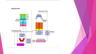
This document provides an introduction to assembly language programming. It discusses how assembly language works at a low level directly with a computer's processor. It outlines the basic components of an assembly language program like editors, assemblers, linkers and debuggers. It also describes the instruction sets, addressing modes, and common directives supported by the 8086 microprocessor. Finally, it provides an example of a simple assembly language program to perform an 8-bit number subtraction.
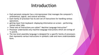
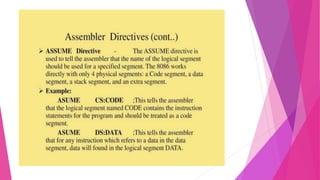
![Addressing modes of 8086
Every instruction of a program has to operate on a date. The different ways in
which a source operand is denoted in any instruction are known as addressing
modes.
There are different types of addressing modes
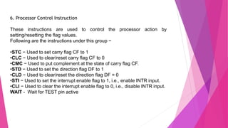
1. Immediate Addressing eg: MOV DL, 08H
2. Register Addressing eg: MOV (CL), (DH)
3. Direct Addressing eg: MOV BX, [1354H]
4. Register Indirect Addressing eg: MOV AX, [BX + 08H]
5. Register relative addressing eg: MOV AX, [BX + 44]
6. Based Indexed addressing eg: MOV CX , [SI + BX]
7. Relative Based Index Addressing eg: MOV DX, [BX + SI + 0AH]
8. Implied / Implicit Addressing eg: CLC](https://image.slidesharecdn.com/alpppt1-210906093323/85/Introduction-to-Assembly-Language-10-320.jpg)
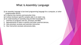
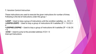
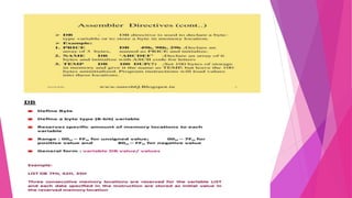
![3. Bit Manipulation Instruction :
i. AND - Used for adding each bit in a byte/word with the corresponding bit in
another byte/word.
ii. OR - Used to multiply each bit in a byte/word with the corresponding bit in another
byte/word.
iii. NOT - Used to invert each bit of a byte or word.
iv. XOR - Used to perform Exclusive-OR operation over each bit in a byte/word with
the corresponding bit in another byte/ word.
v. TEST - Used to add operands to update flags, without affecting operands.
vi. SHR - Used to shift bits of a byte/word towards the right and put zero(S) in MSBs.
vii. SHL/SAL - Used to shift bits of a byte/word towards left and put zero(S) in LSBs.
viii. ROR - Used to rotate bits of byte/word towards the right, i.e. LSB to MSB and to
Carry Flag [CF].
ix. ROL - Used to rotate bits of byte/word towards the left, i.e. MSB to LSB and to
Carry Flag [CF].
x. RCR - Used to rotate bits of byte/word towards the right, i.e. LSB to CF and CF to
MSB.
xi. RCL - Used to rotate bits of byte/word towards the left, i.e. MSB to CF and CF to
LSB.](https://image.slidesharecdn.com/alpppt1-210906093323/85/Introduction-to-Assembly-Language-12-320.jpg)


![5G Explained! A High Level Overview [Introduction]](https://cdn.slidesharecdn.com/ss_thumbnails/5gexplainedahighleveloverview-260119165306-cc137a3e-thumbnail.jpg?width=640&height=640&fit=bounds)


