Download to read offline
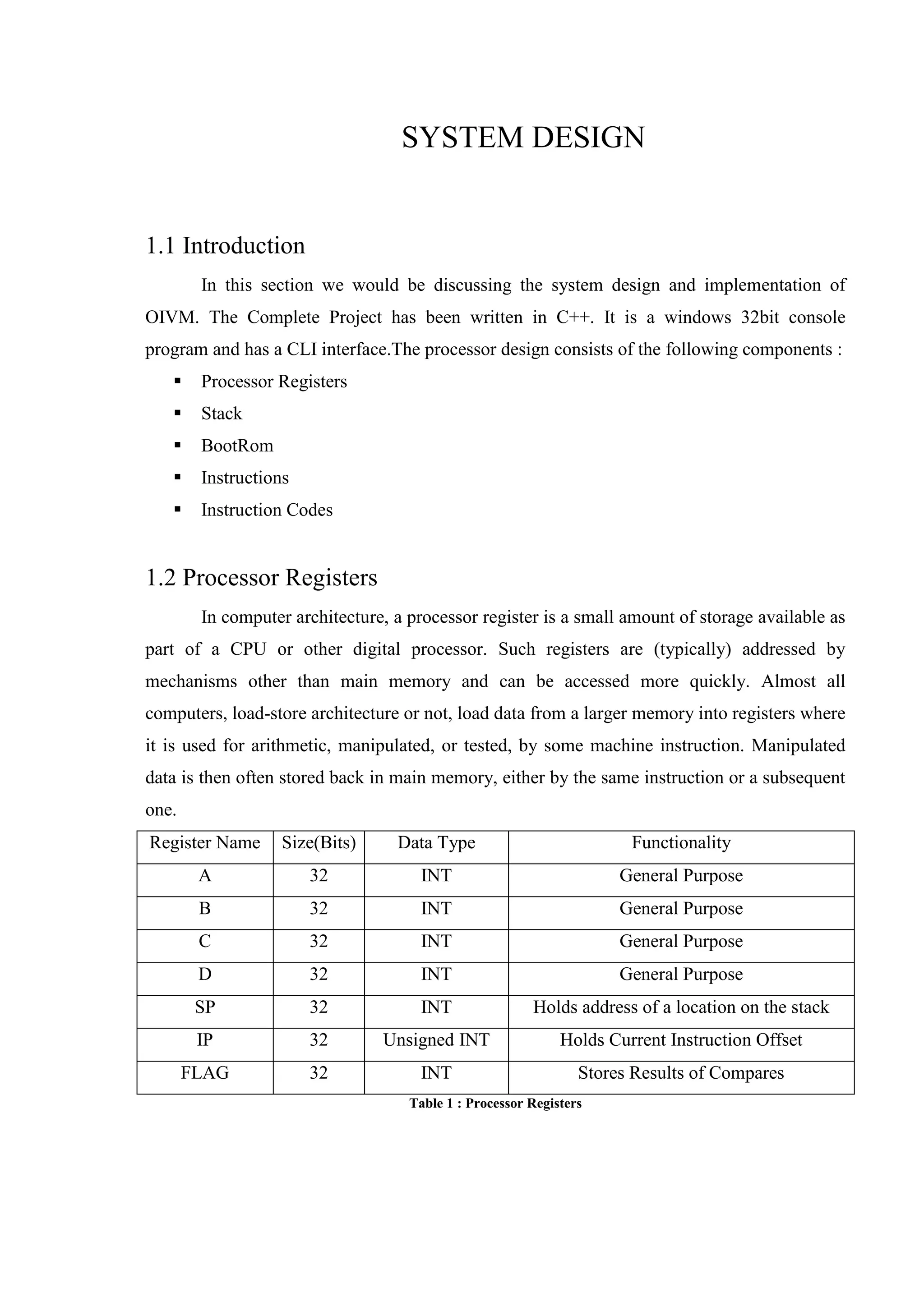

This document summarizes the system design of an OIVM processor. The processor uses C++ and has a CLI interface. It consists of processor registers like A, B, C, D for general purposes and SP, IP, FLAG registers. It also has a stack and bootROM for instructions. The bootROM contains instruction codes that are executed by the RUN() function one by one. Key components like registers, stack, and instructions are described in detail.