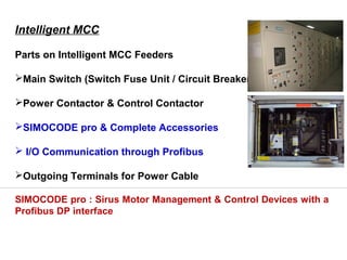
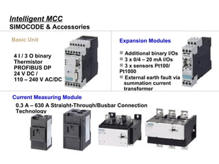
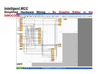
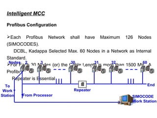
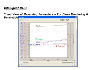
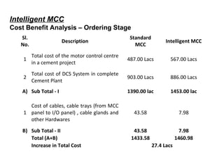
NEW GENERATION MOTOR
CONTROL CENTER
-SIMO CODE SYSTEM
Conventional MCC
Parts on Conventional MCC Feeders
Main Switch (Switch Fuse Unit / Circuit Breaker)
Power Contactor & Control Contactor
Thermal Over Load Relay
 Transducers with Analogue Signals
for Measurement (Optional)
 I/O Communication through Hardware (Control Cable)
Outgoing Terminals for Power & Control Cable
Local Stop
MCC Stop
Interlock
Start
C
O/L relay
230V AC
C
Isolator
Overload
relay
Contactor ©
Local Stop
MCC Stop
Interlock
O/L to DCS
Local Stop to DCS
MCC Stop to DCS
Control supply Healthy
ON Remote ONDCS ON
Local
DCS
Selector Switch
C
230V AC
Drive 1 to Remote
C
Intelligent MCC
Parts on Intelligent MCC Feeders
Main Switch (Switch Fuse Unit / Circuit Breaker)
Power Contactor & Control Contactor
SIMOCODE pro & Complete Accessories
 I/O Communication through Profibus
Outgoing Terminals for Power Cable
SIMOCODE pro : Sirus Motor Management & Control Devices with a
Profibus DP interface
Intelligent MCC
90 KW Motor Feeder with Internal Parts
Intelligent MCC
SIMOCODE & Accessories
4 I / 3 O binary
Thermistor
PROFIBUS DP
24 V DC /
110 – 240 V AC/DC
Basic Unit
Current Measuring Module
0.3 A – 630 A Straight-Through/Busbar Connection
Technology
Expansion Modules
 Additional binary I/Os
 3 x 0/4 – 20 mA I/Os
 3 x sensors Pt100/
Pt1000
 External earth fault via
summation current
transformer
Operator Panel
with display
Operator Panel
5 buttons / 10 LEDs
Intelligent MCC
SIMOCODE & Accessories
Current/Voltage Measuring
Module0.3 A – 630 A /690 V Straight-through/ busbar connection technology
Connection
CableIn various lengths (up to 2.5
m)
Intelligent MCC
Sub Divisions of SIMOCODE pro:
SIMOCODE pro C : A Compact System for Direct & Reversing Starter
with Monitoring & Communication of Current related Parameters only.
Typical SIMOCODE pro C Hardware Configuration
Intelligent MCC
SIMOCODE pro V : A Variable System, which offers numerous in
addition to all of the SIMOCODE pro C Functions.
1. Expandable Binary Input / Output Modules
2. Current / Voltage / Power Related Measurements
3. Expandable Analogue Input / Output Modules
4. Earth Fault Detection
Typical SIMOCODE pro V Hardware Configuration
Intelligent MCC
Applications of SIMOCODE / Intelligent MCC Feeder Module
Controlling, Protection, Measurement & Communication for
 Direct Online Starters
Star Delta Starters
Reversible Starter
Actuation through Soft Starters
Intelligent MCC
Functions of SIMOCODE / Intelligent MCC Feeder Module
Protection Functions
 Thermal Over Load
 Unbalance Protection
 Stalled Rotor Protection
 Thermister Protection Based on Actual Temp. Measurement
 Upper Current Limits & Lower Current Limits
 Earth Fault Protection
 Under Voltage / Over Voltage Protection
 External Interlocking Through Digital Inputs
Intelligent MCC
Functions of SIMOCODE / Intelligent MCC Feeder Module
Measurement Functions
 3 Phase Voltage
 3 Phase Current
 Active Power
 Apparent Power
 Power Factor
 Unbalance Current
 Thermal Model Memory
 Drive Operation Hours
 No. of Over Load Trips
 Last Trip Current
 Drive Stop Time
Intelligent MCC
Simplified Hardware Wiring – By Graphic Editor in the
SIMOCODE
Intelligent MCC
Profibus Networking – Line View
Intelligent MCC
Profibus Configuration
Each Profibus Network shall have Maximum 126 Nodes
(SIMOCODES).
DCBL, Kadappa Selected Max. 60 Nodes in a Network as Internal
Standard.
For Each 30 Nodes (or) the Cable Length is more than 1500 Mtr., A
Profibus
Repeater is Essential
2 3 30 31 32 60Nodes
Repeater
From Processor
EndTo
Work
Station SIMOCODE
Work Station
Intelligent MCC
Monitoring of Last Trip Current – 498% of the Motor Rated
Current
Intelligent MCC
Monitoring of Measured Values
Intelligent MCC
Maintenance Date / Statistical Data
Intelligent MCC
Events List
Intelligent MCC
Control Signals /Drive Status Indications & Digital Signals Status
Intelligent MCC
Detailed Fault & Warning Information
Faults Warnings
Intelligent MCC
Trend View of Measuring Parameters – For Close Monitoring &
Detailed Analysis
KVA
KW
Voltage
Max. Current
L1 Current
Intelligent MCC Motor Protection Settings
Intelligent MCC
Merits
 Sensitive Protection to the Motors like Over Current, Unbalance, Earth Fault,
Starting Current…
 Direct Communication to DCS & Load Center Workstation by Profibus
(Controlling, Measurement & Annunciations). Hence no Instrument I/O Panel is
required.
 Reduces the Commissioning Time of 3 Weeks due to no I/O Panel and its
Cabling / termination
 Online Monitoring of all Motors like Running Status, Current and Power Datas
at CCR and Load Center Workstation.
 Retrieving of motor Trip Records
 Reduced Hardware wiring and hence reduced Maintenance & Breakdowns.
 Vide Range of Feeder Components, hence reduced inventory.
Intelligent MCC
Demerits
 High Initial Cost
 Required Air Conditioned Substation
 Required UPS Power Supply for SIMOCODE Aux. Power
 If Profibus Communication Fails, Entire MCC Feeders will be affected.
 Delayed Communication in responses / feedbacks.
 Required High Skilled Man Power
Sl.
No.
Description
Standard
MCC
Intelligent MCC
1
Total cost of the motor control centre
in a cement project
487.00 Lacs 567.00 Lacs
2
Total cost of DCS System in complete
Cement Plant
903.00 Lacs 886.00 Lacs
A) Sub Total - I 1390.00 lac 1453.00 lac
1
Cost of cables, cable trays (from MCC
panel to I/O panel) , cable glands and
other Hardwares
43.58 7.98
B) Sub Total - II 43.58 7.98
Total (A+B) 1433.58 1460.98
Increase in Total Cost 27.4 Lacs
Intelligent MCC
Cost Benefit Analysis – Ordering Stage
Intelligent MCC
Cost Benefit Analysis – Commissioning Stage
Sl.
No.
Description
Standard
MCC
Intelligent MCC
1
Project Execution Time for Installation,
Testing & Commissioning of MCC’s and
Plant DCS system.
75 days 45 days
2
Per day loss due to delay in Plant
commissioning @ 50% Capacity
22 Lacs
3
Loss due to delay in Plant
Commissioning as above
660 lac 0
Hence, it is recommended that we shall go with Intelligent MCC for Cement
Plant, which is not impacting the project cost but tendering significant
reduction in Execution, Commissioning, Operation and Maintenance Cost
Intelligent MCC
Problem Faced during Commissioning
 Feedback Fault due to Delayed Communication
Problem drastically reduced by fine tuning the Execution Time & Feedback Time
Settings
 Communication Error
Solved by Ensuring Earthing Connectivity of Profibus Cable Shield at all
Terminals
 Failure of Digital Expansion Modules
• Solved by Connecting all Earth Terminals of SIMOCODE to separate Earth Pit
• Solved by Connecting Surge Suppressors to the Power & Control Contactor Coil
Terminal and Suppressed the Surges during Switching.
• Tested all the Digital Modules (Measured Digital Input Energizing Current) and
replaced the Defective Digital Expansion Modules
Intelligent mcc

Intelligent mcc

  • 1.
    NEW GENERATION MOTOR CONTROLCENTER -SIMO CODE SYSTEM
  • 2.
    Conventional MCC Parts onConventional MCC Feeders Main Switch (Switch Fuse Unit / Circuit Breaker) Power Contactor & Control Contactor Thermal Over Load Relay  Transducers with Analogue Signals for Measurement (Optional)  I/O Communication through Hardware (Control Cable) Outgoing Terminals for Power & Control Cable
  • 3.
    Local Stop MCC Stop Interlock Start C O/Lrelay 230V AC C Isolator Overload relay Contactor ©
  • 4.
    Local Stop MCC Stop Interlock O/Lto DCS Local Stop to DCS MCC Stop to DCS Control supply Healthy ON Remote ONDCS ON Local DCS Selector Switch C 230V AC Drive 1 to Remote C
  • 5.
    Intelligent MCC Parts onIntelligent MCC Feeders Main Switch (Switch Fuse Unit / Circuit Breaker) Power Contactor & Control Contactor SIMOCODE pro & Complete Accessories  I/O Communication through Profibus Outgoing Terminals for Power Cable SIMOCODE pro : Sirus Motor Management & Control Devices with a Profibus DP interface
  • 6.
    Intelligent MCC 90 KWMotor Feeder with Internal Parts
  • 7.
    Intelligent MCC SIMOCODE &Accessories 4 I / 3 O binary Thermistor PROFIBUS DP 24 V DC / 110 – 240 V AC/DC Basic Unit Current Measuring Module 0.3 A – 630 A Straight-Through/Busbar Connection Technology Expansion Modules  Additional binary I/Os  3 x 0/4 – 20 mA I/Os  3 x sensors Pt100/ Pt1000  External earth fault via summation current transformer
  • 8.
    Operator Panel with display OperatorPanel 5 buttons / 10 LEDs Intelligent MCC SIMOCODE & Accessories Current/Voltage Measuring Module0.3 A – 630 A /690 V Straight-through/ busbar connection technology Connection CableIn various lengths (up to 2.5 m)
  • 9.
    Intelligent MCC Sub Divisionsof SIMOCODE pro: SIMOCODE pro C : A Compact System for Direct & Reversing Starter with Monitoring & Communication of Current related Parameters only. Typical SIMOCODE pro C Hardware Configuration
  • 10.
    Intelligent MCC SIMOCODE proV : A Variable System, which offers numerous in addition to all of the SIMOCODE pro C Functions. 1. Expandable Binary Input / Output Modules 2. Current / Voltage / Power Related Measurements 3. Expandable Analogue Input / Output Modules 4. Earth Fault Detection Typical SIMOCODE pro V Hardware Configuration
  • 11.
    Intelligent MCC Applications ofSIMOCODE / Intelligent MCC Feeder Module Controlling, Protection, Measurement & Communication for  Direct Online Starters Star Delta Starters Reversible Starter Actuation through Soft Starters
  • 12.
    Intelligent MCC Functions ofSIMOCODE / Intelligent MCC Feeder Module Protection Functions  Thermal Over Load  Unbalance Protection  Stalled Rotor Protection  Thermister Protection Based on Actual Temp. Measurement  Upper Current Limits & Lower Current Limits  Earth Fault Protection  Under Voltage / Over Voltage Protection  External Interlocking Through Digital Inputs
  • 13.
    Intelligent MCC Functions ofSIMOCODE / Intelligent MCC Feeder Module Measurement Functions  3 Phase Voltage  3 Phase Current  Active Power  Apparent Power  Power Factor  Unbalance Current  Thermal Model Memory  Drive Operation Hours  No. of Over Load Trips  Last Trip Current  Drive Stop Time
  • 14.
    Intelligent MCC Simplified HardwareWiring – By Graphic Editor in the SIMOCODE
  • 15.
  • 16.
    Intelligent MCC Profibus Configuration EachProfibus Network shall have Maximum 126 Nodes (SIMOCODES). DCBL, Kadappa Selected Max. 60 Nodes in a Network as Internal Standard. For Each 30 Nodes (or) the Cable Length is more than 1500 Mtr., A Profibus Repeater is Essential 2 3 30 31 32 60Nodes Repeater From Processor EndTo Work Station SIMOCODE Work Station
  • 17.
    Intelligent MCC Monitoring ofLast Trip Current – 498% of the Motor Rated Current
  • 18.
  • 19.
  • 20.
  • 21.
    Intelligent MCC Control Signals/Drive Status Indications & Digital Signals Status
  • 22.
    Intelligent MCC Detailed Fault& Warning Information Faults Warnings
  • 23.
    Intelligent MCC Trend Viewof Measuring Parameters – For Close Monitoring & Detailed Analysis KVA KW Voltage Max. Current L1 Current
  • 24.
    Intelligent MCC MotorProtection Settings
  • 25.
    Intelligent MCC Merits  SensitiveProtection to the Motors like Over Current, Unbalance, Earth Fault, Starting Current…  Direct Communication to DCS & Load Center Workstation by Profibus (Controlling, Measurement & Annunciations). Hence no Instrument I/O Panel is required.  Reduces the Commissioning Time of 3 Weeks due to no I/O Panel and its Cabling / termination  Online Monitoring of all Motors like Running Status, Current and Power Datas at CCR and Load Center Workstation.  Retrieving of motor Trip Records  Reduced Hardware wiring and hence reduced Maintenance & Breakdowns.  Vide Range of Feeder Components, hence reduced inventory.
  • 26.
    Intelligent MCC Demerits  HighInitial Cost  Required Air Conditioned Substation  Required UPS Power Supply for SIMOCODE Aux. Power  If Profibus Communication Fails, Entire MCC Feeders will be affected.  Delayed Communication in responses / feedbacks.  Required High Skilled Man Power
  • 27.
    Sl. No. Description Standard MCC Intelligent MCC 1 Total costof the motor control centre in a cement project 487.00 Lacs 567.00 Lacs 2 Total cost of DCS System in complete Cement Plant 903.00 Lacs 886.00 Lacs A) Sub Total - I 1390.00 lac 1453.00 lac 1 Cost of cables, cable trays (from MCC panel to I/O panel) , cable glands and other Hardwares 43.58 7.98 B) Sub Total - II 43.58 7.98 Total (A+B) 1433.58 1460.98 Increase in Total Cost 27.4 Lacs Intelligent MCC Cost Benefit Analysis – Ordering Stage
  • 28.
    Intelligent MCC Cost BenefitAnalysis – Commissioning Stage Sl. No. Description Standard MCC Intelligent MCC 1 Project Execution Time for Installation, Testing & Commissioning of MCC’s and Plant DCS system. 75 days 45 days 2 Per day loss due to delay in Plant commissioning @ 50% Capacity 22 Lacs 3 Loss due to delay in Plant Commissioning as above 660 lac 0 Hence, it is recommended that we shall go with Intelligent MCC for Cement Plant, which is not impacting the project cost but tendering significant reduction in Execution, Commissioning, Operation and Maintenance Cost
  • 29.
    Intelligent MCC Problem Facedduring Commissioning  Feedback Fault due to Delayed Communication Problem drastically reduced by fine tuning the Execution Time & Feedback Time Settings  Communication Error Solved by Ensuring Earthing Connectivity of Profibus Cable Shield at all Terminals  Failure of Digital Expansion Modules • Solved by Connecting all Earth Terminals of SIMOCODE to separate Earth Pit • Solved by Connecting Surge Suppressors to the Power & Control Contactor Coil Terminal and Suppressed the Surges during Switching. • Tested all the Digital Modules (Measured Digital Input Energizing Current) and replaced the Defective Digital Expansion Modules